
In the field of industrial robotics, the rotary vector reducer stands as a pivotal component for joint actuation, renowned for its compact design, high torque capacity, and precision. Among its core elements, the cycloid wheel plays a critical role in ensuring smooth power transmission and longevity. As the performance of the rotary vector reducer hinges directly on the cycloid wheel’s structural integrity, a thorough understanding of its stress state under operational loads is paramount. In this study, I embark on a comprehensive analysis, combining theoretical mechanics with advanced simulation techniques to evaluate the strength of the cycloid wheel. The rotary vector reducer, often abbreviated as RV reducer, is a two-stage epicyclic gear system that integrates a primary involute gear stage with a secondary cycloidal drive. This configuration grants the rotary vector reducer exceptional advantages over conventional reducers, such as harmonic drives, including higher fatigue strength, larger reduction ratios, superior torsional stiffness, and minimal backlash. My focus here is solely on the cycloid wheel, examining its load distribution through analytical methods and validating its durability via finite element analysis (FEA). This endeavor aims to provide design insights that bolster the reliability of rotary vector reducers in demanding robotic applications.
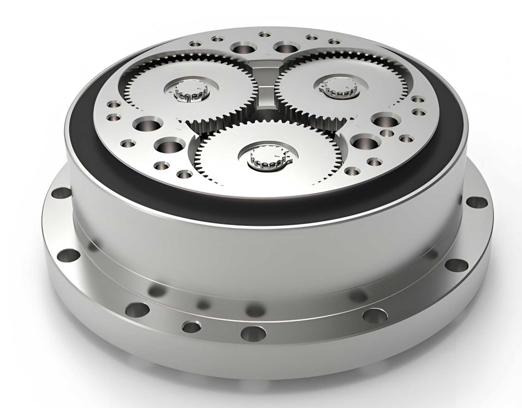
The operational principle of the rotary vector reducer is foundational to grasping the cycloid wheel’s function. The reducer typically comprises an input shaft connected to a servo motor, a set of planetary gears, crankshafts, cycloid wheels, and a pin gear housing. Motion transmission initiates with the input shaft rotating clockwise, driving the sun gear in the first reduction stage. This rotation is transferred to multiple planetary gears, achieving an initial speed reduction. The planetary gears then rotate the crankshafts, which are fixed to the rotary vector reducer’s frame. Each crankshaft undergoes counterclockwise rotation, inducing an eccentric motion (revolution) in the cycloid wheel. With the pin gear housing stationary, the cycloid wheel, while revolving, also experiences a reverse rotation (clockwise spin) due to interaction with the pin teeth. This spin is conveyed back to the crankshaft, causing it to revolve and ultimately drive the output carrier clockwise. The overall transmission ratio, a key metric for the rotary vector reducer, is derived using the fixed carrier method and expressed as:
$$ i_{16} = 1 + \frac{z_2}{z_1} z_5 $$
where \( z_1 \) denotes the number of teeth on the sun gear, \( z_2 \) represents the teeth on the planetary gear, and \( z_5 \) is the number of pin teeth. This formula underscores the high reduction capability intrinsic to the rotary vector reducer, typically ranging from 31 to 171, making it ideal for precision robotic joints. To visualize this intricate mechanism, consider the following illustration:
The rotary vector reducer boasts numerous attributes that cement its dominance in robotics. Its compactness stems from the placement of transmission elements between the carrier’s support bearings, reducing axial dimensions. Enhanced longevity arises from the low-speed cycloidal stage, where multiple teeth engage simultaneously, and the use of bearings minimizes wear. Furthermore, the rotary vector reducer exhibits high stiffness and shock resistance due to a simply supported output structure, contrasting with cantilevered designs. Efficiency ratings of 0.85 to 0.92 are common, attributable to rolling contacts, while meticulous manufacturing yields high motion accuracy with minimal rotational error. These collective traits make the rotary vector reducer a cornerstone in modern automation, driving the need for rigorous component analysis like this study on the cycloid wheel.
Transitioning to the cycloid wheel’s specific role, its engagement with pin teeth underlies the second reduction stage. In an ideal scenario, approximately half the pin teeth would contact the cycloid wheel concurrently. However, practical considerations such as manufacturing tolerances and backlash necessitate a more nuanced approach. Based on empirical evidence, I posit that around seven pairs of teeth are simultaneously engaged during operation, typically numbered 2 through 8 in a clockwise arrangement. To simplify the analysis, I adopt several assumptions: the cycloid wheel material is continuous, homogeneous, and isotropic; friction forces between the cycloid wheel and pin teeth are negligible; and contact loads act purely along the surface normals. Under these conditions, the force model reduces to a static equilibrium problem, where forces converge at a common point, denoted as P in the engagement geometry. The force exerted on each engaged tooth \( i \) can be calculated using the following derived equation:
$$ F_i = \frac{4T_c}{K_1 Z_c r_p} \frac{\sin \varphi_i}{\left(1 + K_1^2 – 2K_1 \cos \varphi_i\right)^{0.5}} $$
Here, \( T_c \) is the resisting torque on the cycloid wheel. For a double-cycloid configuration common in rotary vector reducers, \( T_c = 0.55T \), with \( T \) being the output torque. \( \varphi_i \) is the angular position of the \( i \)-th pin tooth relative to the negative X-axis, \( Z_c \) is the number of cycloid wheel teeth (where \( Z_c = Z_p – 1 \), and \( Z_p \) is the pin tooth count), \( K_1 \) is the shortening factor, and \( r_p \) is the radius of the pin circle. To contextualize this, I reference parameters from an RV-20E type rotary vector reducer, as tabulated below:
| Parameter | Symbol | Value |
|---|---|---|
| Pin circle radius | \( r_p \) | 52.5 mm |
| Pin radius | \( r_{rp} \) | 2 mm |
| Number of pin teeth | \( Z_p \) | 40 |
| Eccentricity | \( a \) | 1 mm |
| Shortening factor | \( K_1 \) | 0.7619 |
| Crank bearing hole radius | \( r_b \) | 26.5 mm |
| Distance between bearing holes | \( s \) | 55 mm |
| Cycloid wheel thickness | \( b_c \) | 9 mm |
Applying the force equation yields the magnitude of loads on teeth 2 through 8. These values are summarized in the subsequent table, providing a clear quantitative basis for subsequent finite element analysis. The direction of each force \( F_i \) is along the line connecting the contact point to point P, as per the engagement kinematics.
| Tooth Number | Angle \( \varphi_i \) (degrees) | Force \( F_i \) (N) |
|---|---|---|
| 2 | 13.5 | 1549.1 |
| 3 | 22.5 | 1920.8 |
| 4 | 31.5 | 2055.0 |
| 5 | 40.5 | 2085.8 |
| 6 | 49.5 | 2063.3 |
| 7 | 58.5 | 2008.1 |
| 8 | 67.5 | 1929.6 |
Additionally, the cycloid wheel is subjected to reaction forces at the crank bearing holes. For analytical simplicity, these are treated as fixed hinge constraints, effectively modeling the supports as immovable in the finite element environment. This completes the theoretical load assessment, paving the way for computational modeling.
Proceeding to three-dimensional modeling, I utilize Pro/ENGINEER software for its robust parametric and curve-handling capabilities. The cycloid wheel’s tooth profile is inherently complex, defined by a trochoidal curve that must be generated via parametric equations. For the RV-20E rotary vector reducer, the profile equations are as follows:
$$ x_c = \left[ r_p – r_{rp} \Phi^{-1}(K_1, \varphi) \right] \cos \left[ (1 – i_H) \varphi \right] – \left[ a – K_1 r_{rp} \Phi^{-1}(K_1, \varphi) \right] \cos (i_H \varphi) $$
$$ y_c = \left[ r_p – r_{rp} \Phi^{-1}(K_1, \varphi) \right] \sin \left[ (1 – i_H) \varphi \right] – \left[ a – K_1 r_{rp} \Phi^{-1}(K_1, \varphi) \right] \sin (i_H \varphi) $$
In these equations, \( \Phi^{-1}(K_1, \varphi) \) represents the amplitude coefficient, \( \varphi \) is the rotation angle of the crank relative to a reference pin tooth, and \( i_H = Z_p / Z_c \) is the transmission ratio between the cycloid wheel and pin gear. Substituting the parameters from Table 1, I generate the profile curve, which serves as a sketch for extruding the solid model. The resultant cycloid wheel features two symmetric bearing holes and a full set of teeth, accurately reflecting the geometry used in the rotary vector reducer. This digital prototype is essential for the ensuing strength simulation, ensuring that analysis aligns with real-world components.
With the model prepared, I shift to finite element analysis using SolidWorks Simulation, a module adept at handling contact mechanics and complex load applications. The material assigned is GCr15 bearing steel, a common choice for rotary vector reducer components due to its high hardness and fatigue resistance. Since GCr15 is not natively available in SolidWorks, I define its properties manually, as detailed in the table below:
| Property | Value |
|---|---|
| Young’s Modulus | 208 GPa |
| Poisson’s Ratio | 0.3 |
| Density | 7.8 g/cm³ |
Boundary conditions are applied to mimic operational constraints: the two crank bearing holes are fixed as hinged supports, restricting translational motion while allowing rotational freedom—a simplification that approximates the bearing interactions in a rotary vector reducer. Load application necessitates careful preparation; I partition the tooth surfaces at contact regions to define distinct faces corresponding to pin engagement points. This enables precise application of the forces \( F_i \) calculated earlier, each directed along the theoretical line of action toward point P. The forces are applied as normal pressures distributed over small areas, simulating the contact patches between the cycloid wheel and pin teeth in the rotary vector reducer. Mesh generation follows, employing a curvature-based mesh with refined elements near stress concentrations, such as tooth roots and hole edges. The mesh statistics typically involve tens of thousands of tetrahedral elements, ensuring solution accuracy without excessive computational cost. This setup encapsulates the static structural analysis of the cycloid wheel within the broader context of rotary vector reducer operation.
Executing the simulation yields comprehensive results on displacement, strain, and stress distributions. The nodal displacement plot reveals that maximum deformation occurs near tooth 8, with a magnitude of 0.02708 mm. Teeth 2 through 7 exhibit progressively varying displacements, correlating with their load magnitudes. This pattern underscores how the rotary vector reducer’s load-sharing among multiple teeth mitigates localized deformations. Strain analysis indicates peak equivalent strain around tooth 6, reaching 0.001928, which aligns with higher force values in that region. The strain distribution is relatively uniform across engaged teeth, testament to the cycloid wheel’s robust design in the rotary vector reducer. Most critically, the von Mises stress contour highlights stress concentrations at tooth engagement zones and adjacent hole peripheries. The maximum stress is observed near tooth 6, quantified at 733.2 MPa. To assess safety, I compare this against the allowable stress for GCr15 steel, which is approximately 1200 MPa based on yield strength considerations. Since 733.2 MPa is well below this threshold, the cycloid wheel demonstrates ample strength margin for typical rotary vector reducer duties. These findings are synthesized in the table below for clarity:
| Metric | Maximum Value | Location | Allowable Value | Safety Status |
|---|---|---|---|---|
| Displacement | 0.02708 mm | Tooth 8 | N/A | Within limits |
| Equivalent Strain | 0.001928 | Tooth 6 area | N/A | Acceptable |
| von Mises Stress | 733.2 MPa | Tooth 6 area | 1200 MPa | Safe |
Delving deeper, the stress distribution pattern offers insights for optimizing the rotary vector reducer. High-stress regions correspond to theoretical contact points, validating the force analysis. The absence of stress exceeding material limits confirms that the cycloid wheel can endure cyclic loading without premature failure, a crucial factor for the longevity of rotary vector reducers in repetitive robotic tasks. Additionally, the strain energy density can be derived from these results, providing a basis for fatigue life predictions. The formula for strain energy per unit volume \( U \) is:
$$ U = \frac{1}{2} \sigma_{ij} \epsilon_{ij} $$
where \( \sigma_{ij} \) and \( \epsilon_{ij} \) are stress and strain tensors, respectively. While not computed explicitly here, the low strain values suggest minimal energy accumulation, further supporting durability. This analysis also highlights the importance of precise manufacturing; deviations in tooth profile or assembly could alter load distribution, potentially elevating stresses. Hence, quality control in producing rotary vector reducer components is paramount.
Expanding on the broader implications, the rotary vector reducer’s performance hinges on synergistic interactions among all parts. The cycloid wheel’s strength, as verified, contributes to the overall torsional rigidity and backlash reduction that characterize rotary vector reducers. Compared to alternative reducers like harmonic drives, the rotary vector reducer offers higher overload capacity and better heat dissipation, partly due to the robust cycloid wheel design. Future work could explore dynamic analyses under varying speeds or thermal effects, which are common in robotic operations. Moreover, material advancements, such as using carburized steels or composites, could further enhance the rotary vector reducer’s power density. The methodology employed here—combining analytical force calculations with FEA—serves as a template for evaluating other critical components, like crankshafts or planetary gears, within the rotary vector reducer assembly.
In conclusion, this study rigorously examines the cycloid wheel, a central element in the rotary vector reducer, through theoretical and finite element frameworks. The force analysis confirms that approximately seven teeth engage simultaneously, with loads calculable via derived formulas. Finite element simulations, leveraging a detailed Pro/E model and SolidWorks Simulation, demonstrate that the cycloid wheel operates within safe stress limits, with peak von Mises stress significantly below the material’s yield strength. These results affirm the structural adequacy of the cycloid wheel for the demanding environments encountered by rotary vector reducers in industrial robotics. By ensuring component reliability, this analysis supports the continued adoption and optimization of rotary vector reducers, driving advancements in automation and precision machinery. The iterative process of design, analysis, and validation encapsulated here underscores the engineering excellence required to sustain the rotary vector reducer’s reputation as a premier motion control solution.