
The advancement of manufacturing technology has propelled industrial robots to the forefront as the core execution units of intelligent manufacturing systems, playing a pivotal role in enhancing product quality and production efficiency. At the heart of these robotic joints lies a critical component responsible for precise motion transmission: the rotary vector reducer. This high-precision transmission device is fundamental to the operational smoothness, positional accuracy, and load-bearing capacity of industrial robots. The performance characteristics of a rotary vector reducer—including high fatigue strength, substantial rigidity, stable backlash precision, smooth transmission, a wide range of transmission ratios, compact structure, and small volume—make it indispensable in demanding robotic applications.
The cycloidal gear, or cycloid disc, is the cornerstone of the secondary reduction stage within a rotary vector reducer. Its geometric design, particularly the accuracy of its tooth profile, is paramount as it directly dictates the meshing characteristics, transmission efficiency, and overall longevity of the reducer. This article presents a comprehensive exploration into the parametric design and rapid physical prototyping of the cycloidal gear. By deriving a streamlined mathematical model for its tooth profile and employing parametric Computer-Aided Design (CAD) techniques, we establish a robust digital foundation. Subsequently, we leverage Fused Filament Fabrication (FFF), a prominent additive manufacturing (AM) or rapid prototyping technology, to fabricate a high-fidelity physical prototype. This integrated approach from digital model to tangible part not only validates the design but also provides a practical, efficient, and cost-effective pathway for functional testing and iterative development of components for the rotary vector reducer.
Transmission Principles and Structural Configuration of the Rotary Vector Reducer
The rotary vector reducer operates on a two-stage reduction principle to achieve high reduction ratios within a compact envelope. The primary reduction stage consists of a planetary gear train. An input shaft, directly connected to the servo motor, drives a central sun gear. This sun gear meshes with multiple planet gears (typically three), which are mounted on a carrier, thereby accomplishing the first level of speed reduction. The unique secondary stage employs a cycloidal speed reduction mechanism. The planet carrier is integrated with several crankshafts (eccentric shafts), which rotate at the same speed as the carrier. A pair of cycloidal gears, offset by 180 degrees from each other, are mounted on these eccentric shafts via bearings.
As the crankshafts revolve, they impart an eccentric motion or “wobble” to the cycloidal gears. These gears mesh with a stationary ring of pin gears (needles) housed in the reducer’s casing. The interaction between the rotating cycloidal lobe and the fixed pins forces the cycloidal gear to rotate on its own axis in a direction opposite to its orbital motion. This combined eccentric revolution and induced rotation results in a very high reduction ratio. The slow rotation of the cycloidal gear is then transferred to the output flange or shaft through a set of pins or a wobble plate mechanism. This sophisticated two-stage process allows the rotary vector reducer to provide exceptionally high torque and precision. The following figure illustrates the core structural principle of this mechanism.
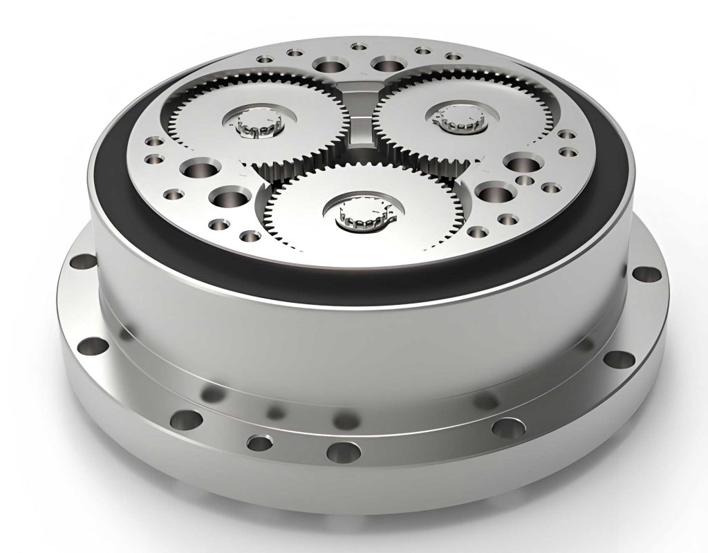
Structurally, a complete rotary vector reducer assembly can be broken down into several key subsystems, as shown in the exploded view model. The main components include:
- Input Unit: Comprising the input shaft connected to the drive motor.
- First-Stage Reduction: The sun gear and planetary gears.
- Second-Stage Reduction: The crankshafts (integral with planet gears), cycloidal gears, needle bearings, and the stationary pin gear ring housed in the main housing or cam.
- Output Unit: The output flange or shaft, often connected via an Oldham coupling or pin-slot mechanism to extract the slow rotation from the wobbling cycloidal gears.
Parametric Modeling of the Cycloidal Gear
The cycloidal gear is a high-precision component with distinct advantages over traditional involute gears, such as a higher contact ratio leading to smoother transmission, lower and more uniform wear, excellent lubrication conditions, and freedom from minimum tooth number limitations, enabling a very compact design. Its tooth profile is not a simple arc or involute but is generated based on the trajectory of a point on one circle as it rolls without slipping around another circle.
Mathematical Foundation: The Cycloidal Tooth Profile Equation
The standard theoretical tooth profile for a cycloidal gear used in a rotary vector reducer is derived from the epitrochoid curve. The coordinates of a point on this curve can be described by a parametric equation. While the complete equation can be complex, it can be simplified for a standard cycloidal drive where the generating roller (pin) radius is considered. The fundamental parameters involved are:
- $r_p$: Radius of the pin gear center circle (the circle on which the centers of the pin gears lie).
- $z_p$: Number of pin gears (needles) in the stationary ring.
- $z_c$: Number of teeth (lobes) on the cycloidal gear. For proper meshing, $z_p = z_c + 1$.
- $a$: Eccentricity (the offset distance of the crankshaft).
- $K$: Shortening coefficient (or trochoid coefficient), defining the shape of the tooth profile.
- $t$: The generating parameter (angle).
The standard parametric equations for the cycloidal gear tooth profile, simplified for modeling, are:
$$
\begin{aligned}
x(t) &= r_p \left[ \sin\left(\frac{2\pi t}{z_c}\right) – \frac{K}{z_p} \sin\left(2\pi \frac{z_p}{z_c} t\right) \right] \\
y(t) &= r_p \left[ \cos\left(\frac{2\pi t}{z_c}\right) – \frac{K}{z_p} \cos\left(2\pi \frac{z_p}{z_c} t\right) \right]
\end{aligned}
$$
The shortening coefficient $K$ is a critical design parameter that determines the shape and strength of the cycloidal tooth. It is defined by the relationship between eccentricity, pin circle radius, and pin count:
$$
K = \frac{a \cdot z_p}{r_p}
$$
Recommended values for $K$ typically range between 0.65 and 0.90 for cycloidal gears with a higher number of teeth, ensuring optimal meshing and force transmission characteristics.
Parameter Definition and Calculation
To proceed with modeling, specific parameters for a sample rotary vector reducer design must be established. The following tables summarize the key geometric and transmission parameters.
| Parameter | Symbol | Value | Unit |
|---|---|---|---|
| Cycloidal Gear Teeth | $z_c$ | 35 | – |
| Pin Gear Teeth | $z_p$ | 36 | – |
| Sun Gear Teeth | $z_s$ | 17 | – |
| Planet Gear Teeth | $z_{pl}$ | 27 | – |
| Total Reduction Ratio | $i_{total}$ | 56 | – |
The pin gear center circle radius $r_p$ is a primary size determinant. It is often selected from standardized ranges based on the reducer size or model.
| Reducer Size Designation | Approximate $r_p$ Range (mm) |
|---|---|
| Size 2 | 106 – 120 |
| Size 3 | 140 – 155 |
| Size 4 | 165 – 185 |
| Size 5 | 210 – 230 |
For our modeling exercise, we select $r_p = 85$ mm (representing a smaller, custom size) and an eccentricity $a = 1.75$ mm. This allows us to calculate the shortening coefficient $K$:
$$
K = \frac{a \cdot z_p}{r_p} = \frac{1.75 \cdot 36}{85} \approx 0.7206
$$
This value falls within a reasonable range for preliminary design. We can now construct the specific parametric equations for our cycloidal gear:
$$
\begin{aligned}
x(t) &= 85 \left[ \sin\left(\frac{2\pi t}{35}\right) – \frac{0.7206}{36} \sin\left(2\pi \cdot \frac{36}{35} t\right) \right] \\
y(t) &= 85 \left[ \cos\left(\frac{2\pi t}{35}\right) – \frac{0.7206}{36} \cos\left(2\pi \cdot \frac{36}{35} t\right) \right]
\end{aligned}
$$
CAD Model Generation
Using a parametric CAD software like SolidWorks, the above equations are implemented to generate the tooth profile curve. The parameter $t$ is varied from an initial value $t_1 = 0$ to a final value $t_2 = 17.5$ to generate one complete lobe (since generating for $t_2 = 35$ would create two overlapping lobes due to symmetry). This curve segment is then mirrored and patterned circularly using the software’s patterning tool to create the full set of 35 teeth. Finally, the 2D profile is extruded to the desired gear width (e.g., 14 mm) to form a solid 3D model of the cycloidal gear. This parametric approach allows for rapid iteration; modifying any fundamental parameter (like $r_p$, $z_c$, or $a$) automatically updates the entire 3D geometry, streamlining the design process for the rotary vector reducer.
Rapid Prototyping via Fused Filament Fabrication (FFF)
Traditional manufacturing of cycloidal gears, such as through hobbing or shaping, requires specialized and expensive tooling, and achieving high precision can be challenging, especially for prototypes or small batches. Additive Manufacturing (AM), specifically Fused Filament Fabrication (FFF), offers a compelling alternative for rapid prototyping and functional testing. FFF is a process where a thermoplastic filament is fed through a heated extruder, melted, and deposited layer-by-layer onto a build platform according to the cross-sectional slices of the digital 3D model.
FFF Process Workflow for the Cycloidal Gear
The journey from the digital CAD model to a physical prototype involves a structured workflow:
- Data Preparation and Format Conversion: The 3D solid model of the cycloid gear, created in SolidWorks (typically a .SLDPRT or .STEP file), is exported in a format compatible with slicing software, most commonly the STL (Stereolithography) format. This format approximates the model’s surfaces with a mesh of triangles.
- Import and Orientation in Slicer Software: The STL file is imported into slicing software (e.g., Ultimaker Cura, PrusaSlicer). The part is oriented on the virtual build plate. For the cycloidal gear, it is typically laid flat to maximize stability and minimize the need for support structures on the critical tooth profiles.
- Print Parameter Configuration: This is a critical step that determines the quality and strength of the final part. Key parameters are set as follows:
- Layer Height: A smaller layer height (e.g., 0.1 mm) increases surface resolution and accuracy but increases print time. A balance must be struck; 0.1-0.2 mm is common for detailed parts.
- Infill Density and Pattern: The internal structure of the part. For a functional test piece that may undergo light mechanical testing, an infill density of 20-40% with a grid or gyroid pattern provides a good compromise between strength, weight, and material usage.
- Print Speed and Temperature: Optimized based on the material used. For Polylactic Acid (PLA), a common prototyping filament, a nozzle temperature of ~200°C and a print speed of 40-60 mm/s are typical starting points.
- Support Structures: Since the cycloidal gear model generally has no severe overhangs when printed flat, support structures can often be disabled for the teeth, preserving their surface quality. Supports may only be needed for the central hub if it has through-holes or complex internal features.
- Slicing and G-code Generation: The slicer software digitally “slices” the 3D model into hundreds of thin horizontal layers (e.g., 140 layers for a 14 mm high gear at 0.1 mm layer height). For each layer, it generates toolpaths for the printer’s extruder. This set of instructions is compiled into a G-code file, which is the machine language for the 3D printer.
- Print Execution: The G-code file is transferred to the 3D printer (e.g., a desktop FFF machine). The build plate and nozzle are heated. The printer then executes the G-code, depositing material layer upon layer until the physical cycloidal gear prototype is complete.
- Post-Processing: Once printing is finished and the part has cooled, it is removed from the build plate. Any support structures (if used) are carefully removed. The part may then undergo additional post-processing such as light sanding to remove layer lines, or chemical smoothing (depending on the material) to improve surface finish and dimensional accuracy for precise assemblies in the rotary vector reducer test rig.
| Parameter | Setting / Value | Rationale |
|---|---|---|
| Material | Polylactic Acid (PLA) | Easy to print, low warp, sufficient rigidity for prototyping. |
| Nozzle Diameter | 0.4 mm | Standard size balancing detail and speed. |
| Layer Height | 0.1 mm | Good surface quality for fine tooth features. |
| Infill Density | 20% | Adequate strength for handling and light testing, saves material/time. |
| Print Speed | 50 mm/s | Balances print quality and build time. |
| Support Structure | Disabled (or ‘Touch Buildplate Only’) | Cycloid tooth profile is self-supporting when printed vertically; avoids scarring on critical surfaces. |
Prototype Accuracy Analysis and Error Compensation
The cycloidal gear in a rotary vector reducer operates under high cyclic loads and tight meshing tolerances. Therefore, evaluating the dimensional accuracy of the FFF-produced prototype is essential. Measurements of the initial prototype often reveal systematic deviations from the nominal CAD dimensions.
Sources of Dimensional Error in FFF
Two primary factors contribute to dimensional inaccuracies in FFF parts, which are critical to consider for precision components like those in a rotary vector reducer:
- Material Shrinkage and Thermal Behavior: Thermoplastics like PLA shrink as they cool from their molten deposition temperature to room temperature. This shrinkage is often non-uniform and can lead to overall part size reduction, warping, and internal stresses.
- Machine and Process-Induced Errors: These include mechanical inaccuracies in the printer’s motion system (e.g., belt slack, step motor resolution), nozzle diameter deviations, and the fundamental “stair-stepping” effect caused by the layer-wise deposition, which affects curved and angled surfaces like cycloidal teeth.
For our gear, a typical finding might be that the actual outer diameter and tooth-to-tooth dimensions are 0.8–1.2 mm smaller than designed, and the central bore for the bearing might be 0.4 mm undersized, preventing proper assembly.
Compensation Strategy for Enhanced Precision
To compensate for these predictable errors, a proactive design modification can be implemented at the CAD modeling stage. Since the primary error manifests as a uniform scaling down, the key generating parameter in the cycloidal equation can be adjusted. The most effective parameter to modify is the pin gear center circle radius $r_p$.
If the measured prototype is consistently smaller, the nominal value of $r_p$ used in the parametric equations is increased. For instance, if the target $r_p$ is 85.0 mm but prints result in features corresponding to an effective $r_p$ of ~84.6 mm, the CAD model should be regenerated using a compensated $r_p^{comp}$ value:
$$
r_p^{comp} = r_p^{nominal} + \delta
$$
where $\delta$ is the empirically determined compensation offset. Based on trial measurements, an offset $\delta = 0.4$ mm might be applied:
$$
r_p^{comp} = 85.0 + 0.4 = 85.4 \text{ mm}
$$
The updated parametric equations become:
$$
\begin{aligned}
x(t) &= 85.4 \left[ \sin\left(\frac{2\pi t}{35}\right) – \frac{0.7206}{36} \sin\left(2\pi \cdot \frac{36}{35} t\right) \right] \\
y(t) &= 85.4 \left[ \cos\left(\frac{2\pi t}{35}\right) – \frac{0.7206}{36} \cos\left(2\pi \cdot \frac{36}{35} t\right) \right]
\end{aligned}
$$
A new prototype printed from this compensated model will, after shrinkage, yield dimensions much closer to the intended 85.0 mm nominal specification. This compensated gear can then be successfully assembled into a test fixture of the rotary vector reducer for functional validation, such as checking smoothness of rotation and meshing alignment.
Conclusion and Implications
This integrated approach demonstrates a powerful methodology for the design and development of critical components for high-precision applications like the rotary vector reducer. By employing a parametric modeling strategy based on the fundamental mathematical equations of the cycloidal tooth profile, designers gain immense flexibility. Modifications to core performance parameters (reduction ratio, size, eccentricity) can be propagated instantly through the 3D model, drastically accelerating the design iteration cycle.
Furthermore, the adoption of Fused Filament Fabrication for rapid prototyping presents significant advantages over conventional machining for early-stage development. It enables the quick, cost-effective production of functional prototypes without the need for dedicated tooling. While inherent material and process limitations of FFF require careful consideration, understanding and compensating for systematic errors—such as by pre-scaling the digital model—allows for the creation of prototypes with sufficient accuracy for form, fit, and basic functional tests.
The synergy between parametric CAD and additive manufacturing creates a robust framework for innovation. For the development of complex assemblies like the rotary vector reducer, this means individual components such as the cycloidal gear, planetary carriers, or even housing segments can be prototyped, tested, and refined rapidly. This workflow not only reduces development time and cost but also encourages exploration of optimized geometries that might be difficult or impossible to manufacture using traditional subtractive methods, paving the way for next-generation, high-performance rotary vector reducer designs.