
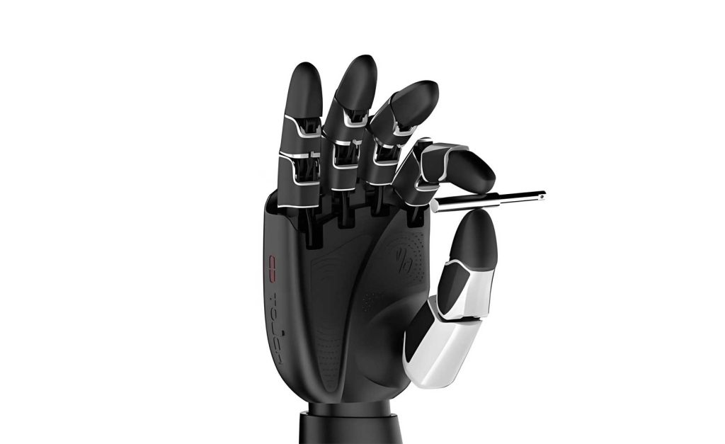
In the evolving landscape of robotics, the ability to interact with complex and unstructured environments has become paramount. As a researcher focused on enhancing robotic manipulation, I have dedicated my efforts to developing advanced control systems for dexterous robotic hands. These end-effectors are critical for performing delicate and adaptive tasks that traditional grippers cannot handle. The dexterous robotic hand, inspired by the human hand’s structure and functionality, offers multi-fingered articulation, enabling versatile grasping and manipulation. However, a significant challenge lies in enabling such a dexterous robotic hand to adapt dynamically to environmental changes. To address this, I have explored master-slave control paradigms, leveraging human intelligence for decision-making while automating precise execution. This article details my first-person perspective on designing a software system for master-slave control of a dexterous robotic hand, emphasizing kinematic mapping, modular software architecture, and incremental PID algorithms.
The core of my work revolves around a master-slave system where a human operator’s hand motions are translated into movements of the dexterous robotic hand. This approach harnesses human perception and adaptability to overcome the limitations of fully autonomous systems. The dexterous robotic hand I worked with mimics the human hand’s morphology, featuring multiple fingers with several joints each, actuated by ultrasonic motors. However, due to anatomical variations between human hands, direct joint-to-joint mapping is infeasible. Instead, I developed a fingertip pose mapping strategy, which forms the foundation of the control system. This method maps the spatial position and orientation of the human operator’s fingertips to the coordinate frame of the dexterous robotic hand, followed by inverse kinematics computations to derive joint angles. For instance, consider the index finger of the dexterous robotic hand. I established a coordinate system at the metacarpophalangeal (MCP) joint axis center, as illustrated in the context of planar kinematics. The fingertip position $(P_x, P_y)$ and inclination angle $\psi$ relative to the $x$-axis are given by:
$$P_x = a_1 + a_2 \cos \phi_1 + a_3 \cos(\phi_1 + \phi_2) + a_4 \cos(\phi_1 + \phi_2 + \phi_3)$$
$$P_y = -[a_2 \sin \phi_1 + a_3 \sin(\phi_1 + \phi_2) + a_4 \sin(\phi_1 + \phi_2 + \phi_3)]$$
$$\psi = \phi_1 + \phi_2 + \phi_3$$
Here, $\phi_1$, $\phi_2$, and $\phi_3$ represent the joint angles of the dexterous robotic hand’s index finger, while $a_1$, $a_2$, $a_3$, and $a_4$ denote the link lengths. These parameters are specific to the mechanical design of the dexterous robotic hand. The inverse kinematics solutions, essential for real-time control, are derived as follows:
$$\phi_1 = \arcsin\left( \frac{k_1^2 + k_2^2 + a_2^2 – a_3^2}{2a_2 \sqrt{k_1^2 + k_2^2}} \right) – \arctan\left( -\frac{k_1}{k_2} \right)$$
$$\phi_2 = \arccos\left( \frac{P_x – a_1 – a_4 \cos(\phi_1 + \phi_2 + \phi_3) – a_2 \cos \phi_1}{a_3} \right) – \phi_1$$
$$\phi_3 = \psi – \phi_1 – \phi_2$$
where $k_1 = P_x – a_1 – a_4 \cos(\phi_1 + \phi_2 + \phi_3)$ and $k_2 = P_y + a_4 \sin(\phi_1 + \phi_2 + \phi_3)$. These equations enable precise control of the dexterous robotic hand’s joint angles based on the human operator’s fingertip poses, implemented in C language on a DSP platform for efficiency. To summarize the kinematic parameters, I have compiled them into a table:
| Parameter | Description | Typical Value (mm) |
|---|---|---|
| $a_1$ | Base link length from origin to MCP joint | 30.0 |
| $a_2$ | Proximal phalanx length | 40.0 |
| $a_3$ | Middle phalanx length | 30.0 |
| $a_4$ | Distal phalanx length | 20.0 |
The software architecture for the dexterous robotic hand is modular, consisting of two primary functional blocks: joint homing and joint motion control. Upon system power-up, initialization routines configure external devices, followed by the homing module that brings all fingers to a predefined “zero” state—fully extended positions. This is crucial for calibrating the dexterous robotic hand and ensuring repeatable operations. The motion control module, the heart of real-time operation, employs incremental PID algorithms to regulate ultrasonic motor speeds, enabling the dexterous robotic hand to track desired trajectories derived from master hand motions. I implemented these modules using C programming in the Code Composer Studio (CCS) environment for DSP, ensuring low-latency execution. The overall control flow is cyclical, involving periodic sampling, PID computation, and actuator adjustment.
Control algorithms play a pivotal role in achieving precise positioning for the dexterous robotic hand. Given the nonlinear and time-varying characteristics of ultrasonic motors, which lack accurate analytical models, I opted for a digital incremental PID controller. This choice is motivated by its simplicity, robustness, and model-free design. The PID controller processes the position error $e(t) = r(t) – y(t)$, where $r(t)$ is the desired position and $y(t)$ is the actual position of a joint in the dexterous robotic hand. The control output $u(t)$ is computed as a linear combination of proportional, integral, and derivative terms. In discrete-time form, used for digital implementation, the incremental PID algorithm is expressed as:
$$\Delta u(k) = K_p \cdot [e(k) – e(k-1)] + K_i \cdot e(k) + K_d \cdot [e(k) – 2e(k-1) + e(k-2)]$$
where $\Delta u(k)$ is the change in control signal at sample $k$, and $K_p$, $K_i$, and $K_d$ are the PID gains. The actual control signal updates as $u(k) = u(k-1) + \Delta u(k)$. This incremental form minimizes computational overhead and reduces integral windup issues. After extensive empirical tuning on the dexterous robotic hand, I arrived at optimal gains: $K_p = 0.9$, $K_i = 0.1$, and $K_d = 0.1$. These values ensure rapid response and stability during delicate manipulations with the dexterous robotic hand. To illustrate the PID parameter effects, consider the following table:
| PID Term | Role in Control | Impact on Dexterous Robotic Hand Performance |
|---|---|---|
| Proportional ($K_p$) | Responds to current error magnitude | Reduces steady-state error but may cause oscillations if too high |
| Integral ($K_i$) | Accumulates past errors to eliminate offset | Improves accuracy for slow movements but can lead to overshoot |
| Derivative ($K_d$) | Predicts future error trends based on rate of change | Damps oscillations and enhances stability during fast motions |
The main program flowchart governs the entire operation of the dexterous robotic hand system. After initialization and joint homing, a timer is activated to define sampling intervals. Upon timer interrupts, the DSP triggers analog-to-digital (A/D) conversion to sample joint positions from potentiometers. Once A/D sampling completes, the actual positions of the dexterous robotic hand joints are read, and PID control laws are invoked to compute control signals for the ultrasonic motors. These signals adjust motor speeds via frequency modulation, driving the dexterous robotic hand toward target positions. The loop continues until all joints reach their destinations, at which point motors are halted via GPIO signals. This structured flow ensures synchronized and accurate control of the dexterous robotic hand.
Data acquisition and processing are critical for maintaining the precision of the dexterous robotic hand. The A/D sampling routine sequentially scans multiple channels to capture potentiometer voltages from all 12 joints. To mitigate noise from zero drift and electromagnetic interference, I implemented a median filtering algorithm. For each joint, $N$ sampled points are stored in an array, sorted, and the middle $N/2$ values are averaged to produce a filtered reading. This method effectively suppresses sporadic outliers, enhancing the reliability of position feedback for the dexterous robotic hand. The A/D process is outlined in a pseudo-code manner: start timer, initiate first channel group, wait for conversion completion, read data, proceed to next group, and so forth. After all groups are processed, data is filtered and forwarded to the control module. The sampling frequency is set to 1 kHz, balancing resolution and real-time demands for the dexterous robotic hand.
Joint homing for the dexterous robotic hand involves bringing each finger to the zero state, defined as full extension with potentiometer outputs at 2.5 V. This voltage corresponds to the mid-range of the sensor, allowing ±160° rotation within linear bounds. The homing algorithm continuously samples joint positions and compares them to the zero-state reference. If a deviation is detected, the ultrasonic motor is driven clockwise or counterclockwise based on the voltage comparison: below 2.5 V triggers reverse motion, while above 2.5 V triggers forward motion. Homing persists until all joints converge to zero, after which the dexterous robotic hand awaits motion commands. This procedure is essential for initial calibration and repeatable performance of the dexterous robotic hand.
Joint motion control in the dexterous robotic hand is executed sequentially across 12 joints to mimic coordinated human hand movements. Although sequential, the DSP’s high processing speed renders the actions nearly simultaneous from a human perspective. The control order is: thumb carpometacarpal joint TMⅡ → index finger MCP joint MPⅡ → middle finger MCP joint MPⅡ → thumb carpometacarpal joint TMⅠ → index finger MCP joint MPⅠ → middle finger MCP joint MPⅠ → thumb MCP joint MP → index finger proximal interphalangeal (PIP) joint → middle finger PIP joint → thumb interphalangeal (IP) joint → index finger distal interphalangeal (DIP) joint → middle finger DIP joint. For each joint, the PID controller computes a speed adjustment, translating to a frequency-modulated voltage for the ultrasonic motor. This enables smooth trajectory tracking for the dexterous robotic hand. The control sequence is summarized below:
| Step | Joint Controlled | Finger | Joint Type |
|---|---|---|---|
| 1 | TMⅡ | Thumb | Carpometacarpal |
| 2 | MPⅡ | Index | Metacarpophalangeal |
| 3 | MPⅡ | Middle | Metacarpophalangeal |
| 4 | TMⅠ | Thumb | Carpometacarpal |
| 5 | MPⅠ | Index | Metacarpophalangeal |
| 6 | MPⅠ | Middle | Metacarpophalangeal |
| 7 | MP | Thumb | Metacarpophalangeal |
| 8 | PIP | Index | Proximal Interphalangeal |
| 9 | PIP | Middle | Proximal Interphalangeal |
| 10 | IP | Thumb | Interphalangeal |
| 11 | DIP | Index | Distal Interphalangeal |
| 12 | DIP | Middle | Distal Interphalangeal |
Throughout my experimentation, I observed that the dexterous robotic hand successfully emulated human hand gestures, such as grasping and pinching, with minimal latency. The fingertip pose mapping, coupled with incremental PID control, provided a robust framework for adaptive manipulation. However, challenges remain, including handling object slippage and enhancing force feedback. Future work on the dexterous robotic hand could integrate tactile sensors and adaptive PID tuning to further improve autonomy. The software design presented here demonstrates a viable pathway toward more intelligent and responsive dexterous robotic hands, capable of operating in dynamic environments.
In conclusion, the development of a master-slave control system for a dexterous robotic hand requires meticulous planning in kinematics, software architecture, and control theory. My approach centered on fingertip pose mapping, modular programming, and empirical PID tuning. The dexterous robotic hand exhibited promising performance in following human operator motions, validating the design choices. As robotics continues to advance, the dexterous robotic hand will play an increasingly vital role in applications ranging from manufacturing to healthcare. I am confident that the methodologies discussed here will contribute to the ongoing evolution of dexterous robotic hands, making them more versatile and accessible for complex tasks.