
In modern agricultural automation, rotary vector reducers play a critical role as core transmission components in robotic joints, enabling precise motion control during crop planting, management, and harvesting. However, these reducers often operate under high-load and variable conditions in complex field environments, leading to wear and fatigue damage in friction pairs, which degrades their load-carrying capacity and service life. To address this, surface modification technologies, such as coatings, offer a promising approach to enhance performance without altering structural designs. In this study, we investigate the load-carrying characteristics of a rotary vector reducer modified by tetrahedral amorphous carbon (ta-C) coating on the cycloidal gear surface. We analyze contact stress and rolling-sliding motion through theoretical and finite element methods, conduct high-torque accelerated degradation tests, and evaluate performance improvements in efficiency, vibration, and wear resistance. Our goal is to provide a viable technical solution for optimizing the durability of rotary vector reducers in agricultural robots, ensuring reliable operation in demanding田间 conditions.
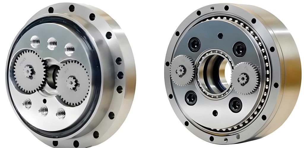
The rotary vector reducer, specifically the RV-20E series with a speed ratio of 81, is widely used in agricultural robotics due to its compact design and high torque output. Key parameters of this rotary vector reducer are summarized in Table 1, which includes dimensions and material properties essential for our analysis. The base material for the cycloidal gear is 20CrMnTi, while the pin gear uses GCr15, both with an elastic modulus of 210 GPa and a Poisson’s ratio of 0.3. Understanding these parameters is fundamental to evaluating the load-carrying behavior of the rotary vector reducer under operational stresses.
| Parameter | Value |
|---|---|
| Planetary gear tooth width (B) | 5 mm |
| Pin gear distribution circle radius (r_p) | 52 mm |
| Number of cycloidal gear teeth (z_c) | 39 |
| Cycloidal gear pitch radius (r_c’) | 35.1 mm |
| Number of pin gears (z_p) | 40 |
| Pin gear radius (r_rp) | 2 mm |
| Cycloidal gear tooth width (b) | 9 mm |
| Pin gear pitch radius (r_p’) | 36 mm |
| Rated output speed (n) | 15 rpm |
| Rated load torque (T_n) | 167 N·m |
To assess the load-carrying capacity of the rotary vector reducer, we first analyze the contact stress between the cycloidal and pin gears, which are critical friction pairs. Based on meshing transmission mechanics and contact theory, the maximum meshing force occurs when the meshing phase angle is 46.19°, calculated from the moment equilibrium. For a load torque of 334 N·m (twice the rated value), the maximum meshing force $F_{\text{max}}$ is derived as:
$$F_{\text{max}} = \frac{4T_c}{K_1 r_p z_c}$$
where $T_c = 0.55M$ (with $M$ as the load torque), $K_1 = a z_p / r_p = 0.6923$ is the short-range coefficient, $r_p$ is the pin gear distribution circle radius, and $z_c$ is the number of cycloidal gear teeth. Substituting values, we obtain $F_{\text{max}} = 523.37$ N. The maximum contact stress $\sigma_{H\text{max}}$ is then calculated using the Hertz contact formula:
$$\sigma_{H\text{max}} = 0.418 \sqrt{\frac{E F_0}{b \rho_{0\text{min}}}}$$
where $E$ is the elastic modulus, $b$ is the cycloidal gear tooth width, $F_0$ is the meshing force at the minimum equivalent curvature radius $\rho_{0\text{min}}$, and other parameters are as defined. This yields $\sigma_{H\text{max}} = 352.73$ MPa. To validate this, we perform a finite element analysis (FEA) on the cycloid-pin transmission mechanism, applying boundary conditions such as a fixed constraint on the crankshaft and a torque of 334 N·m on the pin gear shell. The FEA results, summarized in Table 2, show a maximum contact stress of 346.13 MPa at the cycloid-pin interface, with an error of 1.87% compared to theoretical calculations, confirming accuracy. The stress distribution is uniform along the tooth width, increasing from the edges to the center. Additionally, for the needle-roller bearing pair in the crankshaft, contact stresses are higher on the outer race (414.12 MPa) than the inner race (310.53 MPa), indicating potential wear sites. We also evaluate frictional stress with and without ta-C coating; based on prior ball-on-disk tests, the friction coefficient reduces from 0.15 for uncoated surfaces to 0.05 for coated ones, leading to a significant decrease in frictional stress, as shown in Table 2. This reduction mitigates risks of pitting and scuffing in the rotary vector reducer.
| Component | Stress Type | Value (MPa) | Notes |
|---|---|---|---|
| Cycloid-Pin Pair | Maximum Contact Stress | 346.13 | From FEA, matches theoretical 352.73 MPa |
| Needle-Roller Bearing (Inner Race) | Contact Stress | 310.53 | Lower due to eccentric transmission |
| Needle-Roller Bearing (Outer Race) | Contact Stress | 414.12 | Higher, indicating severe wear potential |
| Cycloid-Pin Pair (Uncoated) | Maximum Frictional Stress | 46.59 | Based on friction coefficient 0.15 |
| Cycloid-Pin Pair (ta-C Coated) | Maximum Frictional Stress | 27.11 | Based on friction coefficient 0.05 |
Next, we analyze the rolling-sliding motion in the cycloid-pin pair, as relative sliding exacerbates wear and affects transmission precision. The relative sliding velocity $V_r$ during meshing is expressed as a function of the meshing phase angle $\phi$:
$$V_r = \left| V_1^t – V_2^t \right| = \left( r_p S^{0.5} + r_{rp} \right) \cdot \frac{(-\omega_3)}{z_c}$$
where $S = 1 + K_1^2 + 2K_1 \cos\phi$, $r_{rp}$ is the pin gear radius, $\omega_3$ is the angular velocity of the crankshaft, and other terms are as defined. The rolling velocities for the pin gear ($V_{1P}$) and cycloidal gear ($V_{2P}$) are given by:
$$V_{1P} = \omega_4 r_{rp} K_1 (K_1 – \cos\phi) / S^2$$
$$V_{2P} = \omega_4 \left[ \frac{r_{rp} K_1 (K_1 – \cos\phi)}{S^2} – \frac{r_p S – r_{rp}}{z_c} \right]$$
where $\omega_4$ is the angular velocity of the cycloidal gear. We compute these velocities over a full meshing cycle, and results are summarized in Table 3. The relative sliding velocity peaks at 0.18 m/s when $\phi = 180°$, while at $\phi = 46.65°$, both rolling velocities approach zero, indicating pure sliding with infinite relative sliding coefficients. This phase angle aligns closely with the maximum meshing force position (46.19°), marking a critical wear point in the rotary vector reducer. The rolling and sliding motions exhibit a symmetric trend, with sliding dominating in specific regions, which can accelerate fatigue damage if not mitigated through surface modifications.
| Meshing Phase Angle $\phi$ (°) | Relative Sliding Velocity $V_r$ (m/s) | Pin Gear Rolling Velocity $V_{1P}$ (m/s) | Cycloidal Gear Rolling Velocity $V_{2P}$ (m/s) | Remarks |
|---|---|---|---|---|
| 0 | 0.05 | 0.12 | 0.10 | Mixed rolling-sliding |
| 46.65 | 0.10 | 0.00 | 0.00 | Pure sliding, severe wear |
| 180 | 0.18 | -0.15 | -0.18 | Maximum sliding velocity |
| 360 | 0.05 | 0.12 | 0.10 | Symmetric to 0° |
To enhance the load-carrying capacity of the rotary vector reducer, we apply a ta-C coating on the cycloidal gear surface using plasma-enhanced chemical vapor deposition (PECVD). The coating process involves acetylene gas flow at 0.02 L/min, with parameters like a target current of 60 A, substrate bias of -160 V, deposition time of 60 minutes, and duty cycle of 60%. This results in a dense, colorful coating approximately 0.8 μm thick, with a multilayer structure including a Cr transition layer and WC layer for improved adhesion. Mechanical tests show the ta-C coating has an elastic modulus of 298.29 GPa, nanohardness of 36.11 GPa, and a critical load for adhesion of 300 mN, representing a 2.39-fold hardness increase over the base material. In dry friction conditions, the friction coefficient reduces from 0.45-0.56 for uncoated surfaces to 0.15-0.17 for coated ones, demonstrating excellent anti-friction properties essential for the rotary vector reducer’s performance.
We conduct high-torque accelerated degradation tests on a rotary vector reducer comprehensive performance test rig, comparing an uncoated reducer (labeled 1#) and a ta-C coated reducer (labeled 2#). The setup includes a drive motor, torque sensors, and a magnetic powder brake, with vibration measured using triaxial piezoelectric accelerometers. Tests are performed under varying loads: for transmission efficiency, we apply step loads from 25% to 100% of the rated torque (167 N·m); for vibration characteristics, a constant 2× rated torque (334 N·m) is used; and for wear analysis, the reducer operates continuously for 180 hours under 2× rated torque. Results are analyzed to evaluate the impact of coating on the rotary vector reducer’s load-carrying behavior.
The transmission efficiency $\eta$ is calculated as:
$$\eta = \frac{T_2}{T_1 i} \times 100\%$$
where $T_2$ is the average output torque, $T_1$ is the average input torque, and $i$ is the theoretical transmission ratio. As shown in Table 4, the ta-C coated rotary vector reducer achieves an efficiency of 94.94% under rated load, nearly 20 percentage points higher than the uncoated version (75.12%). The efficiency standard deviation also decreases by 30%, indicating more stable torque transmission. This improvement stems from the coating’s low friction coefficient, which reduces energy losses and enhances lubrication establishment, crucial for the rotary vector reducer’s operational reliability.
| Load Torque (N·m) | Uncoated Efficiency (%) | ta-C Coated Efficiency (%) | Improvement (Percentage Points) |
|---|---|---|---|
| 41.75 (25% rated) | 68.45 | 85.23 | 16.78 |
| 83.50 (50% rated) | 72.89 | 90.56 | 17.67 |
| 125.25 (75% rated) | 74.33 | 93.12 | 18.79 |
| 167.00 (100% rated) | 75.12 | 94.94 | 19.82 |
Vibration characteristics are assessed by analyzing time-domain signals from axial, tangential, and radial directions. The root mean square (RMS) values of vibration acceleration are computed, and results in Table 5 show that the ta-C coated rotary vector reducer exhibits significantly lower RMS values across all directions, with reductions up to 40% compared to the uncoated one. Periodic spikes in vibration are also minimized, indicating smoother meshing and reduced impact forces. We further model the relationship between temperature and RMS using nonlinear fitting, expressed as $y = a e^{bx} + c$, where $y$ is RMS and $x$ is temperature. For instance, in the radial direction, the fitted equation is $y = 0.046e^{15.37x} + 3.01$ with $R^2 > 0.98$, highlighting that vibration intensity increases exponentially with temperature, underscoring the importance of thermal management in the rotary vector reducer.
| Direction | Uncoated RMS (m/s²) | ta-C Coated RMS (m/s²) | Reduction (%) |
|---|---|---|---|
| Axial | 4.85 | 2.92 | 39.79 |
| Tangential | 4.12 | 2.48 | 39.81 |
| Radial | 5.23 | 3.14 | 39.96 |
Post-test wear analysis involves examining key components like the cycloidal gear, pin gear, sun gear, and bearing holes using scanning electron microscopy (SEM) and energy-dispersive spectroscopy (EDS). The uncoated rotary vector reducer shows severe fatigue wear, with features such as spalling, pitting pits, and oxidative damage, as indicated by high oxygen content (up to 22.5% on sun gear surfaces). In contrast, the ta-C coated reducer displays only mild fatigue wear, with smoother surfaces and reduced oxidation (oxygen content below 6.57%). EDS results in Table 6 confirm the presence of W elements in coated surfaces, demonstrating coating retention and protection. The wear patterns align with contact stress distributions from FEA, validating that the coating effectively mitigates friction-induced damage in the rotary vector reducer.
| Component | Surface Condition | Oxygen Content (wt%) | Carbon Content (wt%) | Key Observations |
|---|---|---|---|---|
| Sun Gear | Uncoated | 22.50 | 24.44 | Severe oxidation and spalling |
| Sun Gear | ta-C Coated | 6.53 | 17.74 | Mild fatigue, reduced oxidation |
| Cycloidal Gear | Uncoated | 3.42 | 11.99 | Pitting and fatigue wear |
| Cycloidal Gear | ta-C Coated | 4.21 | 10.13 | Smooth, with W detected |
| Bearing Hole | Uncoated | 6.57 | 13.86 | Oxidative wear |
| Bearing Hole | ta-C Coated | 2.34 | 12.73 | Minimal damage |
In conclusion, our study comprehensively analyzes the load-carrying characteristics of a rotary vector reducer modified by ta-C coating on the cycloidal gear surface. Through theoretical and finite element methods, we determine that maximum contact stress reaches 346.13 MPa at a meshing phase angle of 46.19°, with severe sliding wear occurring at 46.65° due to pure sliding conditions. Experimental tests demonstrate that the ta-C coating significantly enhances the performance of the rotary vector reducer: transmission efficiency improves by nearly 20 percentage points to 94.94% under rated load, vibration RMS values decrease by up to 40%, and wear mechanisms shift from severe fatigue and oxidation to mild fatigue with reduced oxidative damage. These findings validate that ta-C coating offers excellent anti-friction, anti-impact, and anti-oxidation properties, effectively boosting the load-carrying capacity and service life of rotary vector reducers in agricultural robotics. This work provides a practical technical pathway for optimizing the durability of rotary vector reducers in harsh field environments, ensuring reliable operation for tasks like crop harvesting and planting.
To further support our analysis, we derive additional formulas relevant to the rotary vector reducer’s performance. For instance, the sliding coefficients $u_1$ and $u_2$ for the cycloidal and pin gears are given by:
$$u_1 = \frac{V_{12}}{V_{1M}}, \quad u_2 = \frac{V_{21}}{V_{2M}}$$
where $V_{12}$ and $V_{21}$ are relative sliding velocities, and $V_{1M}$ and $V_{2M}$ are rolling velocities. At $\phi = 46.65°$, these coefficients approach infinity, confirming extreme wear risk. Additionally, the temperature-vibration relationship can be modeled with exponential functions, emphasizing the need for cooling strategies in rotary vector reducers under high loads. Overall, integrating surface coating technologies with detailed mechanical analysis offers a robust approach to advancing the reliability of rotary vector reducers in agricultural automation, contributing to more efficient and durable robotic systems for future farming applications.