
The rotary vector reducer is a critical high-precision component, especially within industrial robotic systems, where its durability directly determines the operational reliability and service life of the robot. Among its internal components, the needle roller bearings are particularly susceptible to wear failure due to their compact radial dimensions and the complex dynamic contact loads they endure. This wear leads to a significant decline in the performance of the rotary vector reducer, loss of its original transmission accuracy, and can ultimately result in mechanical failure. Understanding the dynamic wear characteristics of these bearings is therefore paramount for optimizing their design and enhancing the longevity of the entire reducer system.
This study focuses on developing a coupled dynamics and wear model for the cycloidal-pinwheel and needle roller bearing transmission mechanism within a rotary vector reducer. The model integrates contact multi-body dynamics with Archard’s wear theory to simulate and analyze the intricate wear process under operational conditions.
1. Dynamics Modeling of the Cycloidal-Pinwheel and Bearing Transmission
1.1 Multi-Body Dynamics Model for the Rotary Vector Reducer
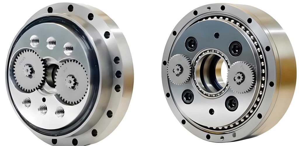
A multi-body dynamics model is established to capture the complex interactions within the rotary vector reducer. The system, as shown in Figure 1, comprises two crankshafts, two cycloidal gears (or wheels), a planet carrier (output), and a stationary pinwheel. The influence of support bearings and the crankshaft bearings (needle roller bearings) is considered.
The generalized coordinate vector for the system with 15 degrees of freedom is defined as:
$$ \mathbf{q} = [x_{g1}, y_{g1}, \theta_{g1}, x_{g2}, y_{g2}, \theta_{g2}, x_{c1}, y_{c1}, \theta_{c1}, x_{c2}, y_{c2}, \theta_{c2}, x_o, y_o, \theta_o]^T $$
where $(x_{gi}, y_{gi}, \theta_{gi})$ are the coordinates for crankshaft $i$, $(x_{ci}, y_{ci}, \theta_{ci})$ for cycloidal gear $i$, and $(x_o, y_o, \theta_o)$ for the planet carrier. The system’s mass matrix $\mathbf{M}$ is a diagonal matrix containing the masses and moments of inertia of all components.
The equations of motion are derived using Lagrange’s equation with multipliers:
$$ \begin{bmatrix} \mathbf{M} & \mathbf{\Phi_q}^T \\ \mathbf{\Phi_q} & \mathbf{0} \end{bmatrix} \begin{bmatrix} \mathbf{\ddot{q}} \\ \mathbf{\lambda} \end{bmatrix} = \begin{bmatrix} \mathbf{Q}_G \\ \mathbf{\gamma} – 2\alpha \mathbf{\dot{\Phi}} – \beta^2 \mathbf{\Phi} \end{bmatrix} $$
where $\mathbf{\Phi_q}$ is the Jacobian of the constraint equations $\mathbf{\Phi}$, $\mathbf{\lambda}$ are Lagrange multipliers, $\mathbf{Q}_G$ is the generalized force vector, and $\mathbf{\gamma}$ is the right-hand side of the acceleration constraints. Baumgarte stabilization parameters $\alpha$ and $\beta$ are used.
The contact between the cycloidal gear teeth and the pinwheel pins is modeled using a nonlinear Hertzian contact force model. The relative distance $\mathbf{d}_{ij}$ between a pin center $P_j$ and points $Q_i$ on the cycloidal tooth profile is calculated. Contact is detected when $||\mathbf{d}_{ij}|| – r_{rp} \le 0$, where $r_{rp}$ is the pin radius. The contact deformation (depth) is $\delta_{ij} = r_{rp} – ||\mathbf{d}_{ij}||$. The point with the maximum deformation $\delta_{ij}^{max}$ is taken as the contact point. The normal contact force $F_j$ is then:
$$ F_j = K_{pc} (\delta_{ij}^{max})^{10/9} + C_{pc} \cdot c_c \cdot v_{jn} $$
where $K_{pc}$ is the contact stiffness, $C_{pc}$ is the contact damping, $v_{jn}$ is the relative normal velocity, and $c_c$ is a damping scaling factor dependent on $\delta_{ij}^{max}$.
1.2 Needle Roller Bearing Contact Dynamics
The needle roller bearing is modeled as an array of rollers between the crankshaft’s eccentric journal (inner race) and the cycloidal gear’s bore (outer race). The relative eccentricity vector $\mathbf{e}$ between the centers of the inner and outer races is:
$$ \mathbf{e} = \mathbf{r}_i – \mathbf{r}_o $$
The eccentricity distance is $e = \sqrt{\mathbf{e}^T \mathbf{e}}$ and its unit vector is $\mathbf{n}_e = \mathbf{e} / e$.
Assuming rollers are uniformly distributed and rotate at an average cage speed $\omega_r$, the angular position of the $k$-th roller is:
$$ \phi_k = \phi_{k0} + \omega_r t $$
The radial deflection $\delta_{rk}$ of the $k$-th roller due to the eccentricity is:
$$ \delta_{rk} = e_x \cos \phi_k + e_y \sin \phi_k $$
The corresponding relative radial velocity $v_{rk}$ is calculated similarly from the velocity components of $\mathbf{e}$.
The normal contact force $F_{rk}$ between the roller and the races (assuming both contacts are load-sharing) is modeled as:
$$ F_{rk} = K_r (\delta_{rk})^{10/9} + D_r \cdot c_c \cdot v_{rk} $$
where $K_r$ is the total roller-race contact stiffness and $D_r$ is the contact damping.
2. Wear Model for Needle Roller Bearings
2.1 Archard Wear Theory
The Archard wear model provides the fundamental relationship for adhesive/abrasive wear. The volumetric wear $dV$ over a sliding distance $ds$ is:
$$ \frac{dV}{ds} = K \frac{F}{H} $$
where $K$ is the dimensionless wear coefficient, $F$ is the normal load, and $H$ is the material hardness. For a contact area $dA$ with pressure $p$, the wear depth $dh$ per sliding distance is:
$$ \frac{dh}{ds} = \frac{K}{H} p = \mu p $$
where $\mu = K/H$ is the wear coefficient. The total wear depth is obtained by integration: $h = \mu \int p \, ds$.
2.2 Dynamic Contact Pressure Calculation
Based on Hertzian theory, the contact half-widths $b_{ir}$ and $b_{or}$ for the inner and outer race contacts with a roller are:
$$
b_{ir} = \sqrt{ \frac{4 F_r \rho_{ir}}{\pi L_r} \left( \frac{1-\nu_c^2}{E_c} + \frac{1-\nu_r^2}{E_r} \right) }, \quad
b_{or} = \sqrt{ \frac{4 F_r \rho_{or}}{\pi L_r} \left( \frac{1-\nu_c^2}{E_c} + \frac{1-\nu_r^2}{E_r} \right) }
$$
where $\rho_{ir} = \frac{r_i r_r}{r_i + r_r}$ and $\rho_{or} = \frac{r_o r_r}{r_o – r_r}$ are the relative curvatures, $L_r$ is the roller effective length, and $E$, $\nu$ denote elastic modulus and Poisson’s ratio for cycloidal gear (c), roller (r), and crankshaft (cr). The maximum contact pressures are:
$$ p_{ir} = \frac{F_r}{2 b_{ir} L_r}, \quad p_{or} = \frac{F_r}{2 b_{or} L_r} $$
2.3 Wear Coefficient for Boundary Lubrication
For the low-speed, boundary lubrication regime typical in rotary vector reducer bearings, a dynamic wear factor model is adopted. The wear coefficients $k_{ir}$ and $k_{or}$ are given by:
$$
k_{ir}(t,n) = 3.981 \times 10^{-29} \cdot C_{ir}(t,n)^{1.219} \cdot G^{7.377} \cdot S_{ir}(t,n)^{1.589} / E’_r
$$
where $C_{ir} = F_r / (b L_r E’ \rho_{ir})$ is the dimensionless load parameter, $G = \zeta E’$ is the dimensionless materials parameter ($\zeta$ is pressure-viscosity coefficient), $S_{ir} = \rho_{ir} / (R_{a\_rms} \rho_{cp})$ is the dimensionless surface roughness parameter, and $E’_r$ is the reduced elastic modulus for the roller-inner race contact. A similar expression holds for $k_{or}$.
2.4 Calculation of Wear Depth and Dynamic Interaction
The wear rate (depth per unit sliding distance) at the contact points is:
$$ I_{h-ir}(t,n) = k_{ir}(t,n) \cdot p_{ir}(t,n), \quad I_{h-or}(t,n) = k_{or}(t,n) \cdot p_{or}(t,n) $$
The incremental sliding distance $ds$ is related to the rolling/sliding motion. For a given slip ratio $\xi$ (e.g., $\xi=0.05$), the sliding distance per time step is $ds = 2\xi b$, where $b$ is the contact half-width. The instantaneous wear depth increment is:
$$ dh_{I-ir}(t,n) = I_{h-ir}(t,n) \cdot ds_{ir}(t,n) $$
Cumulative wear for a point on the race is obtained by summing contributions from all rollers that pass over it during operation. The total wear depth $h_{I-in}$ at a specific point on the inner race after $N$ revolutions of the planet carrier is calculated by appropriately accumulating $dh_{I-ir}$ from all roller engagements at that angular location.
Critically, the accumulated wear alters the raceway profile, effectively increasing the bearing clearance at worn locations. This modified profile is fed back into the dynamics model by updating the effective radial deflection $\delta_{rk}$ for subsequent time steps, creating a coupled dynamics-wear simulation loop as illustrated in Figure 7 of the reference.
3. Case Study: RV20E-121 Rotary Vector Reducer
3.1 Model Parameters
The proposed model is applied to analyze an RV20E-121 rotary vector reducer. Key geometric and dynamic parameters are listed below.
| Parameter Description | Symbol | Value |
|---|---|---|
| Number of Cycloidal Gear Teeth | $z_c$ | 39 |
| Number of Pinwheel Pins | $z_p$ | 40 |
| Pin Radius | $r_{rp}$ | 2.0 mm |
| Pinwheel Distribution Radius | $r_p$ | 52.0 mm |
| Crankshaft Eccentricity | $e$ | 0.9 mm |
| Inner Race (Eccentric Journal) Radius | $r_i$ | 10.25 mm |
| Outer Race (Cycloidal Bore) Radius | $r_o$ | 13.25 mm |
| Roller Radius | $r_r$ | 1.5 mm |
| Number of Rollers | $Z_r$ | 16 |
| Input Speed | $n_g$ | 2000 rpm |
| Output Load Torque | $T_{load}$ | 167 Nm |
| Roller-Race Contact Stiffness | $K_r$ | $5.1 \times 10^8$ N/m |
| Slip Ratio (Inner/Outer Race) | $\xi_{ir}, \xi_{or}$ | 0.05, 0.05 |
3.2 Wear Characteristics of the Inner Raceway
The simulation results for the inner raceway (crankshaft eccentric journal) show non-uniform wear distribution. The maximum cumulative wear depth after 10,000 hours of operation reaches approximately 3.97 µm. The wear is significantly more severe on the side corresponding to the positive Y-axis direction (perpendicular to the line connecting the two eccentricity centers) when the reducer operates in one direction (counter-clockwise output). This asymmetry arises because the specific rollers in this region experience higher dynamic loads due to the changing instant center of rotation in the cycloidal drive. For bi-directional operation, wear is more pronounced on both sides of the Y-axis (top and bottom).
3.3 Wear Characteristics of the Outer Raceway
The wear on the outer raceway (cycloidal gear bore) is also non-uniform but generally less severe than on the inner raceway for this rotary vector reducer configuration. The maximum simulated wear depth is about 3.11 µm after 10,000 hours. For one-directional operation, the wear concentrates on the clockwise side of the bore circumference relative to the gear’s rotation. This aligns with the region where the bore is consistently in a “pressed” state against the rollers during operation. In bi-directional operation, the wear is more significant in the circumferential direction of the cycloidal wheel (tangential direction) rather than the radial direction connecting the bore center to the gear center.
4. Experimental Wear Test Validation
To validate the simulation model, a durability fatigue test was conducted on an RV20E-121 rotary vector reducer. After the test, the reducer was disassembled, and the key components were cleaned.
4.1 Inner Raceway Wear Measurement
The crankshaft eccentric journals were inspected using a coordinate measuring machine (CMM). The measured profile confirmed uneven wear. The maximum wear depth on the eccentric journal was found to be approximately 12.0 µm, showing a similar distribution pattern to the simulation: greater wear on the surface perpendicular to the eccentricity direction and less wear along the eccentricity direction itself. The quantitative difference between simulated (3.97 µm) and measured (12.0 µm) wear can be attributed to factors like actual lubrication conditions, material properties, and possible run-in wear not captured in the steady-state wear model.
4.2 Outer Raceway Wear Measurement
The bore surfaces of the cycloidal gears were also measured via CMM. The results indicated a maximum wear depth of about 5.6 µm. The wear pattern showed more significant material removal on one side of the bore circumference, consistent with the predicted concentration of wear in the circumferential direction. This correlation between the simulated wear distribution trends and the experimental measurements validates the fundamental approach of the coupled dynamics-wear model for the rotary vector reducer’s needle roller bearings.
5. Conclusion
This study established a coupled dynamics and wear model for the needle roller bearings within a rotary vector reducer. The model integrates multi-body contact dynamics with Archard’s wear theory, enabling the analysis of wear under complex dynamic loads. The application to an RV20E-121 reducer revealed that wear on the bearing raceways is highly non-uniform. The inner raceway (crankshaft journal) experiences more severe wear than the outer raceway (cycloidal bore). Wear on the inner raceway is greatest in the direction perpendicular to the crankshaft’s eccentricity, while wear on the outer raceway concentrates in the circumferential direction of the cycloidal wheel. Experimental tests on a fatigued reducer confirmed these non-uniform wear patterns, lending credibility to the model. This analysis provides a valuable tool for optimizing needle roller bearing design parameters in rotary vector reducers, with the ultimate goal of improving their service life and maintaining transmission accuracy.