
In the era of intelligent manufacturing, the demand for industrial robots has surged, placing higher requirements on transmission accuracy, load capacity, and overall performance. The rotary vector reducer, a core component in industrial robots, plays a pivotal role in ensuring high precision, efficiency, and longevity. However, traditional studies focusing on single-load conditions are insufficient to meet the practical application needs of rotary vector reducers in diverse operational environments. Ignoring the impact of special loading conditions—such as sinusoidal and square-wave impulsive loads—on transmission accuracy can severely compromise the performance and lifespan of industrial robots. Therefore, investigating the influence mechanisms of variable load conditions on transmission error is crucial for enhancing the transmission accuracy and applicability of domestic rotary vector reducers. In this study, we explore the variation patterns of transmission error under different working conditions through multi-body dynamics simulation and experimental validation, aiming to provide insights for improving the design and application of rotary vector reducers.
Recent research on transmission error in rotary vector reducers has covered error溯源, error coupling, and accuracy improvements. For instance, studies have analyzed the impact of component原始 errors on transmission error and their propagation processes. Others have proposed multi-factor equivalent models for transmission error modeling. While these contributions have advanced the field, practical transmission accuracy in rotary vector reducers remains inadequate, with issues such as load loading forms and gradient changes still needing addressing. Under fixed reducer specifications, load magnitude and gradient are primary influencing factors. Existing work has examined fixed loads’ effects on transmission efficiency, friction torque under no-load conditions, and负载 impacts on deformation modes, identifying the cycloidal-pin gear transmission as a key source of transmission error. Some researchers have compensated for contact deformation in cycloidal gears under rated loads to improve accuracy, while others analyzed transmission error curves under fixed conditions or explored harmonic reducer error variations with speed and load. Nonetheless, most studies overlook variable load conditions, limiting their relevance to real-world scenarios. Hence, this study comprehensively considers constant, square-wave, and sinusoidal loads to analyze transmission error under different gradients and loading forms, revealing their influence laws through error theory and dynamics simulation.
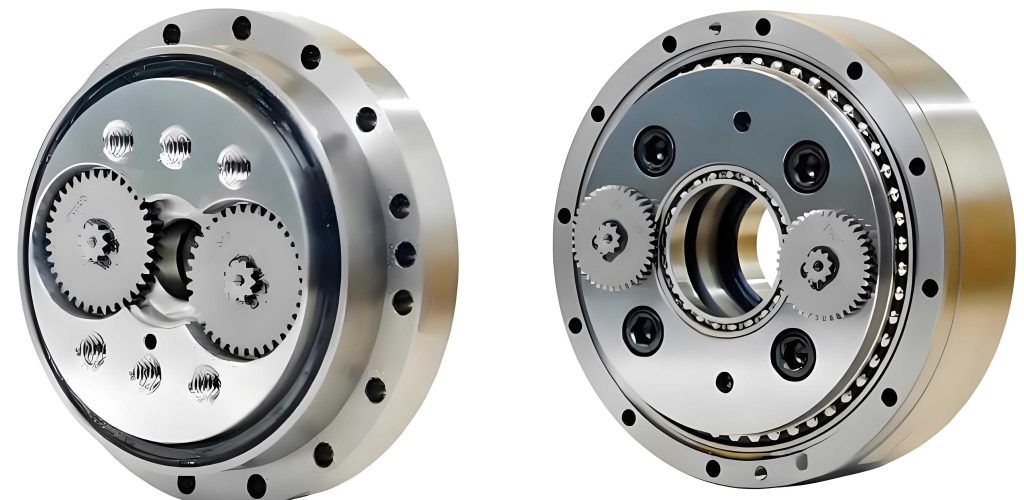
The rotary vector reducer consists of two main stages: a primary planetary gear transmission and a secondary cycloidal-pin gear transmission. The planetary gear transmission includes an input shaft and planetary gears, while the cycloidal-pin gear transmission comprises crankshafts, cycloidal gears, a pin gear housing, and multiple pins. The working principle involves power transmission from the input shaft to the planetary gears, which are fixed to the crankshafts. Due to eccentric structures on different shaft segments, the crankshafts rotate and drive the cycloidal gears, causing them to revolve around their centers with a radius equal to the crankshaft eccentricity. When the pin gear housing is fixed, the cycloidal gears’ rotation drives the output flange connected to the planet carrier, completing motion output. The transmission ratio is given by: $$i = 1 + \frac{Z_2}{Z_1} \times Z_5$$ where $Z_2$ is the number of planetary gear teeth, $Z_1$ is the number of input shaft teeth, and $Z_5$ is the number of pin teeth.
Transmission error is a critical performance metric for assessing the transmission accuracy of a rotary vector reducer, defined as the difference between the actual output rotation angle and the theoretical output rotation angle. It can be expressed as: $$\Delta \phi = \theta_r – \theta_{or} = \theta_r – \theta_s / i$$ where $\theta_r$ is the actual output rotation angle, $\theta_{or}$ is the theoretical output rotation angle, $\theta_s$ is the theoretical input rotation angle, and $i$ is the overall transmission ratio of the rotary vector reducer. By integrating this equation, we obtain: $$\Delta \phi(t) = (\omega_{out} – \omega_{in} / i) \cdot \Delta t(t)$$ where $\Delta \phi(t)$ is the transmission error at time $t$, $\omega_{out}$ is the output angular velocity, $\omega_{in}$ is the theoretical input angular velocity, and $\Delta t(t)$ is the time interval between sampling points. This formulation indicates that transmission error results from the product of velocity error at each moment and the corresponding sampling interval.
To simulate the dynamic behavior of the rotary vector reducer, we employed multi-body dynamics software. The model was simplified by removing non-essential components such as bolts, chamfers, and fillets to ensure求解 accuracy and reduce computation time. Based on the structural principles and geometric constraints of the rotary vector reducer, appropriate constraints were added to mimic real-world conditions. The constraint types between components are summarized in the following table:
| Component Name | Constraint Type |
|---|---|
| Input Shaft and Output Flange | Revolute Joint |
| Planetary Gear and Output Flange | Revolute Joint |
| Input Shaft and Planetary Gear | Contact/Collision |
| Planetary Gear and Crankshaft | Fixed Joint |
| Crankshaft and Output Flange | Revolute Joint |
| Crankshaft and Cycloidal Gear | Revolute Joint |
| Cycloidal Gear and Pin | Contact/Collision |
| Housing and Ground | Fixed Joint |
| Pin and Housing | Fixed Joint |
| Output Flange and Housing | Revolute Joint |
Boundary conditions were established to investigate the effects of different gradients and loading forms on transmission error. Three loading drive forms were set: constant loading, square-wave loading, and sinusoidal loading, each with gradients of 100, 200, 300, and 400 N·m. A driving speed was applied to the input shaft using a step function: $$\text{Driving Speed} = 7200 \cdot \text{STEP}(time, 0, 0, 1, 1) \, \text{deg/s}$$ This means the input speed increases from 0 to 7200 deg/s over 0 to 1 seconds. A reverse torque was applied to the output flange, defined as follows for each loading form:
- Constant loading: $$\text{Torque} = \text{STEP}(time, 1, 0, 2, 100000) \, \text{N·mm}$$
- Square-wave loading: $$\text{Torque} = \text{STEP}(\sin(2\pi \cdot time), 0.01, 95000, 0.01, 105000) \, \text{N·mm}$$
- Sinusoidal loading: $$\text{Torque} = 5000 \cdot \sin(8 \cdot time) + 100000 \, \text{N·mm}$$
The WSTIFF integrator was selected for求解 precision, with a simulation time of 7 seconds and 700 steps. The output angular velocity curve showed a stable increase during 0-1 seconds, then stabilized around 88.88 deg/s with minor fluctuations, consistent with theoretical calculations.
Under constant loading, the transmission error curves for one rotation of the output flange were analyzed. The results indicated that at the same speed, transmission error curves under different loads exhibited high similarity. The fluctuation amplitude of transmission error increased with load, showing a positive correlation. Frequency domain analysis revealed peaks at 0.02 Hz and 0.28 Hz across all loads, corresponding to the crankshaft-cycloidal gear contact frequency and planetary gear meshing frequency, respectively. The highest amplitude near 0 Hz aligned with the cycloidal-pin meshing frequency, confirming that cycloidal-pin engagement is a primary source of transmission error in the rotary vector reducer. At 100 N·m, the amplitude near 0 Hz was higher due to meshing instability under light loads.
For square-wave loading, the transmission error trends were similar to constant loading, with peaks at 0 Hz, 0.02 Hz, and 0.28 Hz. As load increased, the influence of these peaks on transmission error grew, with the 0 Hz error having the greatest impact. At 400 N·m,接近 the rated load, reduced stability led to noticeable peaks at 0.01 Hz and 0.29 Hz. Data processing using linear interpolation smoothed突变 points, masking abrupt changes in square-wave loads.
Under sinusoidal loading, transmission error patterns and frequency peaks remained consistent with constant and square-wave loads, suggesting that loading form has a minor overall impact. However, at 100 N·m and 400 N·m, distinct peaks appeared at 0.01 Hz and 0.29 Hz, indicating poor stability under low loads due to insufficient load support and under high loads due to increased meshing forces and cumulative deformations. Sinusoidal loading introduced more abnormal peaks due to continuous load variations, increasing instability and error波动 but not significantly affecting overall transmission error.
To quantify the impact of different gradients and loading forms on transmission error, we used standard deviation to measure the dispersion and fluctuation of transmission error curves. The standard deviation is calculated as: $$\sigma = \sqrt{\frac{\sum_{i=1}^{n} (x_i – \bar{x})^2}{n}}$$ where $\sigma$ is the standard deviation, $x_i$ is individual sample data, $\bar{x}$ is the average transmission error, and $n$ is the total number of samples. The standard deviations for various conditions are summarized in the following table:
| Load (N·m) | Constant Loading | Square-wave Loading | Sinusoidal Loading |
|---|---|---|---|
| 100 | 14.154 | 14.056 | 14.172 |
| 200 | 14.695 | 14.898 | 15.416 |
| 300 | 16.817 | 17.312 | 17.930 |
| 400 | 19.196 | 19.032 | 19.485 |
The standard deviation increased with load under fixed speed, indicating greater dispersion in transmission error. For fixed speed and load, sinusoidal loading exhibited the highest standard deviation due to continuous load changes, followed by square-wave loading and constant loading, in descending order of impact. Although square-wave loading showed lower error波动 in simulation, its abrupt load changes can exacerbate vibrations in the rotary vector reducer, accelerating component wear. Thus, square-wave loading should be avoided in practical applications.
Experimental validation was conducted using a comprehensive performance测试 platform for rotary vector reducers, consisting of a servo drive system, grating angular encoders, and reducer fixtures. The tested rotary vector reducer model was RV-40E. Under no-load conditions at 100 rpm, the measured transmission error was 57.467 arcseconds. Simulation under the same conditions yielded error fluctuations between -20 and 25 arcseconds. Discrepancies arose from manual installation errors, such as coaxiality misalignment during mounting, which increased experimental values. Without load support, output shaft摆动 amplified coaxiality effects, contributing to higher errors. Ignoring coaxiality errors, experimental and simulation results were approximately consistent, verifying the simulation’s合理性.
In conclusion, we established a three-dimensional model of the rotary vector reducer and simulated its operation via dynamics仿真. The output angular velocity matched theoretical values, and experiments confirmed simulation validity. Different gradient loads affect transmission error, with error increasing positively with load, primarily accumulating at frequencies of 0.02 Hz and 0.28 Hz. Low-load conditions reduce stability due to insufficient force, while high-load conditions increase errors from component deformations and gear backlash. Loading forms also influence transmission error; quantified by standard deviation, sinusoidal loading has the highest dispersion, followed by square-wave and constant loading. Square-wave loading’s突变 values can intensify vibrations,加速 component damage, so it should be minimized in practice. This study enhances understanding of rotary vector reducer behavior under variable loads, aiding in precision improvement and application adaptability. Future work could explore additional loading scenarios or incorporate manufacturing errors for更 comprehensive analysis of the rotary vector reducer’s performance.