
The relentless pursuit of precision in industrial robotics brings us to a critical, yet often underappreciated, component: the rotary vector reducer. As someone deeply involved in the pursuit of motion accuracy, I have seen firsthand how the performance ceiling of a robot is often defined by the quality of its joints, and at the heart of these joints lies the RV transmission system. This sophisticated gearbox is prized for its compact size, high torque capacity, and excellent backlash characteristics. However, its dominance in precision applications is perpetually challenged by the manufacturing quality of its most complex element: the cycloidal disk, or as it’s often called, the cycloidal gear. The quest to measure its manufacturing errors accurately is not just a technical exercise; it is the fundamental barrier between a good robot and a great one.
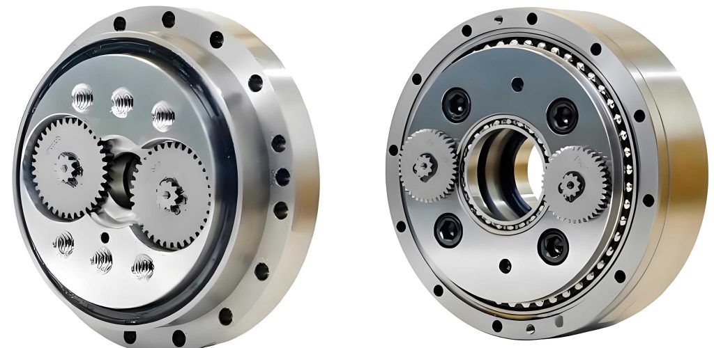
My journey into this field began with a simple, frustrating observation: while the global market for advanced robotics soared, the feedback on domestically produced rotary vector reducers consistently pointed to shortcomings in motion accuracy and operational lifespan. The root cause, as analysis and practical teardowns revealed, almost invariably traced back to excessive and uncontrolled manufacturing errors in the cycloidal disks. The industry’s traditional go-to measurement techniques—methods like the double-pin gauge span measurement or tip-to-root distance checks—were, to put it bluntly, inadequate. They offered simplicity but sacrificed the comprehensive insight needed for high-precision manufacturing. They were statistical spot-checks, not definitive maps of the entire tooth form. The alternative, using a Coordinate Measuring Machine (CMM), promised a full contour map but introduced its own set of problems: high cost, the need for specialized and often proprietary software, and complex, time-consuming data processing that was ill-suited for production line environments.
This dilemma led to a fundamental question: could we leverage the existing infrastructure already common in precision gear manufacturing? Most high-quality gear production facilities are equipped with sophisticated gear measuring centers. These machines are marvels of coordinated motion control, designed to measure complex gear geometries like involute helicoids with nanometer-level precision. The challenge was that their software and kinematic models were built around the known laws of involute generation. The cycloidal profile of a rotary vector reducer’s disk, especially after modification, follows a different set of mathematical rules entirely. The mission became clear: adapt the hardware capability of the gear measuring center to the unique problem of the cycloidal disk. This article is a synthesis of that journey, focusing on a pivotal innovation in measurement methodology: the adoption of the node as the singular reference point for single-tooth measurement.
The Geometrical Enigma: Understanding the Cycloidal Profile
To measure something, one must first understand what it is supposed to be. The tooth profile of a cycloidal disk is not a simple arc or an involute curve. It is a segment of a curtate epicycloid’s equidistant curve—a wave-like, closed contour where the tooth flanks seamlessly blend into the root and tip fillets. This complexity arises from its generation principle. Unlike an involute gear whose form is defined primarily by module and pressure angle, a cycloidal disk’s geometry is governed by a set of six key forming parameters:
- Eccentricity, \( a \): The distance between the center of the cycloidal disk and the center of the pin gear.
- Pin radius, \( r_{rp} \): The radius of the cylindrical pins it meshes with.
- Pin circle radius, \( r_p \): The radius of the circle on which the pins are distributed.
- Profile shift modification, \( \Delta r_p \): A radial adjustment of the pin circle.
- Equidistant modification, \( \Delta r_{rp} \): An adjustment to the rolling circle radius.
- Turning angle modification, \( \Delta \delta \): A rotational adjustment during generation.
These modifications (\( \Delta r_p \), \( \Delta r_{rp} \), \( \Delta \delta \)) are crucial. They are intentionally introduced to create backlash, allow for lubrication, compensate for elastic deformation under load, and improve the load distribution across multiple teeth in the rotary vector reducer. However, they also break the pure mathematical link between the disk’s rotation and the theoretical epicycloid, making measurement based on pure generation kinematics impossible for a modified profile.
The foundation of any measurement is a rigorous theoretical model. For a cycloidal disk, the position vector \( \mathbf{R_0} \) of a point on the ideal tooth profile and its corresponding unit normal vector \( \mathbf{n_0} \) can be derived from the theory of gearing as functions of the meshing phase angle \( \theta \) and the set of forming parameters \( \Phi = \{ r_p, r_{rp}, a, \Delta r_p, \Delta r_{rp}, \Delta \delta \} \):
$$
\mathbf{R_0} = \mathbf{R_0}(\theta; \Phi), \quad \mathbf{n_0} = \mathbf{n_0}(\theta; \Phi)
$$
Since a gear measuring center controls the rotary table’s angle \( \varphi \) and the radial axis \( X \) (or \( Y \)) simultaneously, we must relate \( \varphi \) to \( \theta \). This relationship, \( \varphi = f(\theta, \Phi) \), allows us to re-parameterize the profile for measurement, yielding the core model for our software:
$$
\mathbf{R} = \mathbf{R}(\varphi; \Phi), \quad \mathbf{n} = \mathbf{n}(\varphi; \Phi)
$$
This pair of equations gives us, for every rotation angle \( \varphi \) of the disk on the measuring center, the exact \( (x, y) \) coordinate of the ideal tooth surface and the direction in which a probe should approach it. Generating this dense set of \( (\varphi, \mathbf{R}, \mathbf{n}) \) tuples is the first critical step in programming the measurement.
The Measurement Conundrum: Full Contour vs. Single Flank
With the theoretical model in hand, the next challenge is measurement strategy. Drawing inspiration from gear measurement, two primary paths emerge for evaluating the rotary vector reducer cycloid disk:
| Measurement Strategy | Process | Primary Advantage | Primary Disadvantage |
|---|---|---|---|
| Full Contour Measurement | The probe tracks every tooth on the disk in one continuous revolution. Data is collected for the entire circumference. | Provides a complete picture of all errors (tooth-to-tooth and cumulative) in a single setup. | Results are contaminated by the indexing error of the measuring center’s rotary table itself. It conflates gear error with machine error. |
| Single Flank Measurement | The probe measures only one tooth flank at a time. The disk is manually or automatically re-indexed for each tooth. | Eliminates the influence of the measuring center’s rotary table indexing error. Isolates the true tooth form error. | Requires a highly repeatable method to align each tooth precisely to the same measurement coordinate system. |
The choice between these strategies hinges on the selection of a Reference Point. This is the digital anchor, the point on the tooth where the theoretical and the real-world profiles are assumed to coincide for the purpose of alignment. In a full contour measurement, where the disk rotates continuously, a natural reference is needed to “stitch” the data from all teeth into a coherent whole. The traditional choice, analogous to involute gear measurement, is the tooth root. However, the root of a cycloidal tooth is a very shallow, low-slope region. A tiny error in radial positioning here translates to a significant angular misalignment due to the near-vertical surface normal, making precise alignment challenging.
This is where our proposed new method offers a paradigm shift. For single-flank measurement, we propose abandoning the root and instead using the node as the reference point. In gear theory, the node is the point on the line of action where the pitch circles of two mating gears roll without slip. For a rotary vector reducer cycloid disk meshing with a pin gear, it is the point on the tooth flank where the direction of force transmission is theoretically optimal and where profile modifications are typically minimal. The design philosophy of profile modification is to preserve the perfect conjugacy around the working zone (near the node) while introducing relief near the tip and root. Therefore, the actual manufactured surface is most likely to conform to the theoretical design at the node. Furthermore, the pressure angle at the node is well-defined and stable. Using it as a reference provides a robust, functionally relevant anchor that is less sensitive to probe approach errors than the root or tip. This method forms the cornerstone of our new approach to isolating and quantifying the true manufacturing error of the disk.
The New Methodology: Node-Referenced Single-Flank Measurement
The practical implementation of this method on a gear measuring center involves a carefully orchestrated sequence. The core mechanism is discrete-point contact tracing. The machine does not attempt to simulate the generation motion of a modified cycloid (which is nonlinear and unknown); instead, it uses the theoretical model to guide a probe along the intended path, maintaining contact through closed-loop feedback.
1. Measurement Kinematics & Probing: The probe, typically a ruby sphere, is first driven to the theoretical coordinate of the node on the tooth to be measured. A gentle “touch-off” routine aligns the actual disk surface to the machine’s coordinate system at this point. Then, following the pre-calculated list of \( (\varphi, \mathbf{R}) \) points, the machine’s controller orchestrates a simultaneous move of the rotary axis \( C \) and the linear radial axis \( X \) or \( Y \). A 3D analog probe constantly monitors deflection. If the probe begins to lose or gain contact, the radial axis makes a compensating move to maintain a near-zero deflection, ensuring the probe sphere’s center follows a path that is precisely one probe radius \( \rho \) away from the actual surface. The recorded data is the trajectory of the probe center, \( \mathbf{R_q^*} \).
2. Data Processing Core – From Probe Path to Surface Error: The raw probe center data must be processed to reveal the error of the actual workpiece surface \( \mathbf{R^*} \). The relationship between the probe path, the actual surface, and the ideal surface is given by:
$$
\mathbf{R_q^*} = \mathbf{R^*} + \rho \cdot \mathbf{n} \quad \text{(Probe path)}
$$
$$
\mathbf{R^*} = \mathbf{R} + \delta \cdot \mathbf{n} \quad \text{(Actual surface)}
$$
Combining these, and knowing the ideal \( \mathbf{R} \) and \( \mathbf{n} \) from our model, we can solve for the profile form error \( \delta \) at each measured point. \( \delta \) is the scalar signed distance between the ideal and actual surface along the ideal surface’s normal direction. This is the fundamental manufacturing error metric.
3. Data Alignment – The Best-Fit Algorithm: Even with careful node referencing, small residual misalignments (due to part loading, temperature, etc.) will exist between the measured point cloud and the theoretical model. To remove this “rigid body error” and isolate the pure form error, we perform a best-fit alignment. We treat the measured profile \( \Sigma_{\mathbf{R^*}} \) as a point cloud that can be rotated by an angle \( \alpha \) and translated by \( (\Delta x, \Delta y) \) to best match the theoretical profile \( \Sigma_{\mathbf{R}} \). We seek the transformation matrix \( \mathbf{M} \) that minimizes the sum of squared distances between corresponding points. The objective function is:
$$
F_{\text{min}}(\Delta x, \Delta y, \alpha) = \sum_{i=1}^{n} \left[ (x_i – x_i(u))^2 + (y_i – y_i(u))^2 \right] \rightarrow \text{min}
$$
Solving this minimization problem yields the optimal alignment parameters. Applying this transformation to \( \mathbf{R^*} \) before calculating \( \delta \) ensures we are measuring shape error, not setup error.
Error Evaluation: From Profile to Cumulative Pitch
Once the best-fit aligned data for all teeth (measured individually) is obtained, we can evaluate standard gear error metrics, which are just as critical for a rotary vector reducer as for any precision gear.
Profile Deviation (\( F_\alpha \)): This is the maximum range of the profile form error \( \delta \) over the evaluated tooth flank. It indicates how accurately the tooth shape was manufactured.
Single Pitch Deviation (\( f_{pt} \)): The difference between the actual angular pitch (angle between corresponding points on adjacent teeth) and the theoretical pitch (\( 2\pi / Z_a \), where \( Z_a \) is number of teeth). It affects noise and smoothness. For a point at a defined radius \( R_{\text{eval}} \) (often the node radius), the linear deviation is:
$$
f_{pt}(i) = R_{\text{eval}} \cdot \left[ \varphi(i) – \varphi(i-1) – \frac{2\pi}{Z_a} \right]
$$
Total Cumulative Pitch Deviation (\( F_p \)): The maximum variation in the cumulative angular position of teeth over the entire disk. This is the primary indicator of motion accuracy and directly impacts the positioning repeatability of the robot joint using the rotary vector reducer. It is calculated from the sum of single pitch errors:
$$
F_p = R_{\text{eval}} \cdot \left[ \max_{1 \le k \le Z_a} \left( \sum_{i=1}^{k} \Delta \varphi(i) \right) – \min_{1 \le k \le Z_a} \left( \sum_{i=1}^{k} \Delta \varphi(i) \right) \right]
$$
where \( \Delta \varphi(i) = \varphi(i) – \varphi(i-1) – 2\pi / Z_a \).
Experimental Validation and Comparative Analysis
To validate this node-reference method, we conducted measurements on a commercial gear measuring center, adapting its open architecture to run our custom measurement driver software. The test subject was a cycloidal disk with 41 teeth, designed for a pinion with 42 pins and key parameters including an eccentricity \( a = 1 \text{ mm} \) and both profile shift and equidistant modifications.
We performed two sets of measurements on the same disk:
1. Full Contour Measurement (using a best-fit root reference from the continuous data).
2. Single Flank Measurement (using the node reference point as described, measuring teeth #1, #11, #21, and #31).
The results were processed and the key error metrics were compared. The table below summarizes the findings:
| Error Metric | Full Contour Measurement Result | Node-Reference Single Flank Measurement (Avg. of 4 teeth) | Implication & Agreement |
|---|---|---|---|
| Profile Error \( F_\alpha \)) | 18.0 µm | 12.4 µm | Single-flank method shows lower error, as it is not inflated by table indexing error. Both indicate a comparable quality level. |
| Single Pitch Dev. \( f_{pt} \)) | 6.1 µm | 6.0 µm | Excellent agreement. This high-frequency error is largely independent of the reference method. |
| Total Cumulative Pitch Dev. \( F_p \)) | 27.6 µm | 25.8 µm | Very close agreement. The small difference may be attributed to the full contour method including the measuring center’s own rotary error. |
| Radial Runout \( F_r \)) | 9.2 µm | N/A (Single flank) | A whole-gear metric only derivable from full contour data. |
The plots of the profile error were particularly telling. The full-contour plot showed a slight sinusoidal modulation superimposed on the tooth form error, a classic signature of an axis eccentricity or indexing component. The single-flank plots for the four measured teeth were cleaner, showing primarily the form error from the grinding process itself. The close agreement on \( f_{pt} \) and \( F_p \), which are derived from angular positions, validates the accuracy of the node-based indexing for single teeth. The best-fit alignment parameters for the single-flank data were remarkably small (\( \alpha \approx 0.003^\circ \), \( \Delta x, \Delta y \approx 3-4 \mu m \)), confirming the stability and repeatability of using the node as a physical datum.
Conclusion and Perspective
The development and validation of this node-referenced, single-flank measurement method represent a significant step forward in the metrology of rotary vector reducer components. By rethinking the fundamental reference point, we have devised a technique that leverages the high-precision motion control of standard gear measuring centers while isolating the true manufacturing errors of the cycloidal disk from the errors of the measuring instrument itself. This method provides a functionally relevant, accurate, and practical solution for quality control in the production of high-performance rotary vector reducers.
Looking forward, this methodology does more than just measure; it enables control. The detailed, accurate error maps it generates can be fed back into the manufacturing process—whether it be grinding, honing, or lapping—to implement corrective actions, closing the loop between design, manufacturing, and verification. As the demand for ever-more precise and reliable robots continues to grow, such advanced, accessible metrology techniques will be indispensable in pushing the boundaries of what is possible, ensuring that the heart of the robot’s joint beats with unwavering precision.