
In the field of industrial robotics, precision motion control is paramount, and the rotary vector reducer plays a critical role in achieving high accuracy in joint mechanisms. As a researcher focused on transmission system design, I have extensively studied the backlash characteristics of rotary vector reducers, given their widespread use alongside harmonic reducers in robotic joints. Backlash, defined as the lag in output shaft motion when the input shaft reverses direction, directly impacts positioning accuracy and overall system performance. In this paper, I present a detailed analysis of backlash in rotary vector reducers, employing probabilistic methods and sensitivity analysis to develop a computational model implemented in Matlab. The goal is to provide engineers with a tool for efficient tolerance allocation during the design phase, ensuring that backlash remains within stringent limits, often below 1 arcminute.
Rotary vector reducers are complex planetary gear systems that combine involute gear stages with cycloidal pin-wheel stages, forming a closed differential transmission. This configuration offers advantages such as high reduction ratios, substantial stiffness, excellent motion accuracy, and smooth operation. However, the multi-stage nature introduces multiple sources of backlash, which can be categorized into geometric, thermal, and elastic components. Here, I concentrate on geometric backlash, arising solely from dimensional and geometric variations in components. Understanding and minimizing this backlash is essential for applications like industrial robots, where precision is non-negotiable.
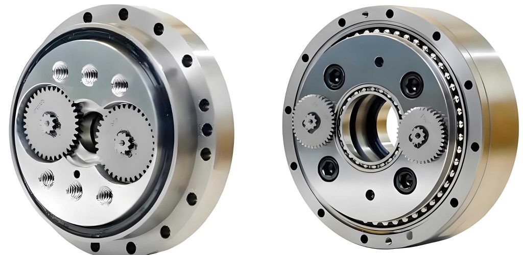
To analyze backlash systematically, I first established mathematical models for both the involute gear stage and the cycloidal pin-wheel stage. The total backlash of a rotary vector reducer is the sum of contributions from these two stages, with the cycloidal stage having a more direct and significant impact due to its position in the transmission chain. For the involute gear stage, key factors influencing backlash include: average deviation of base tangent length, center distance deviation, radial runout of gear rings, parallelism errors of gear axes, radial composite errors (encompassing profile and pitch deviations), eccentricities from rolling bearings, and clearances between keys and keyways. Each factor contributes to the output shaft backlash, and their effects can be quantified through derived equations.
For instance, the backlash due to average base tangent length deviation, denoted as $\Delta E_W$, is given by:
$$B_{tEw} = -\frac{180 \times 60}{\pi r_1 i} \times \frac{\Delta E_W}{\cos \alpha}$$
where $\alpha$ is the pressure angle, $r_1$ is the pitch radius of the central involute gear, and $i$ is the total transmission ratio of the rotary vector reducer. Similarly, backlash from center distance deviation $\Delta f_a$ is expressed as:
$$B_{tfa} = -\frac{180 \times 60}{\pi r_1 i} \times 2 \Delta f_a K_a \tan \alpha$$
with $K_a = \frac{\sin \alpha’}{\sin \alpha}$, where $\alpha’$ is the operating pressure angle. The radial runout error $\Delta F_r$ contributes as:
$$B_{tFr} = \frac{180 \times 60}{\pi r_1 i} \times \Delta F_r K_a \tan \alpha$$
Other factors follow analogous formulations, leading to the total involute stage backlash $B_I$ as the sum of individual contributions: $B_I = B_{tEw} + B_{tfa} + B_{tFr} + \ldots$
For the cycloidal pin-wheel stage, backlash is influenced by modifications to the cycloidal wheel, manufacturing tolerances, and assembly clearances. Key factors include: modifications of the cycloidal wheel (such as equidistant, shift, and angle modifications), errors in these modifications, errors in the pin circle radius, errors in pin radius, fit clearances between pins and pin holes, radial runout of the cycloidal wheel, circumferential position errors of pin holes, cumulative pitch errors of the cycloidal wheel, and clearances in the crank bearings. The backlash from shift modification $\Delta r_p$, for example, is calculated as:
$$B_1 = \frac{180 \times 60 \times 2}{\pi} \times \left( \frac{\Delta r_{rp}}{a z_c} – \Delta r_p \frac{\sqrt{1 – K_1^2}}{a z_c} + \frac{\delta}{2} \right)$$
where $a$ is the eccentricity, $z_c$ is the number of cycloidal wheel teeth, $\Delta r_{rp}$ is the equidistant modification, $\delta$ is the angle modification, and $K_1$ is a geometric parameter. Errors in the pin circle radius $\delta r_p$ contribute as:
$$B_2 = \frac{180 \times 60}{\pi} \times \frac{2 \delta r_p \sqrt{1 – K_1^2}}{a z_c}$$
Cumulative pitch error $\Delta F_p$ leads to:
$$B_3 = -\frac{180 \times 60}{\pi} \times \frac{K_1 \Delta F_p}{a z_c}$$
and crank bearing clearance $\Delta u$ results in:
$$B_u = \frac{180 \times 60}{\pi} \times \frac{\Delta u}{a_0}$$
where $a_0$ is a reference dimension. The total cycloidal stage backlash $B_{II}$ is the sum of these and other terms: $B_{II} = \sum B_i + B_u$. Consequently, the overall backlash $B$ of the rotary vector reducer is: $B = B_I + B_{II}$.
In practice, manufacturing errors are not deterministic but statistical in nature. Therefore, I employed a probabilistic approach to compute backlash more realistically. Assuming machining errors follow a normal distribution and eccentricity errors follow a Rayleigh distribution, the mean $\mu$ and variance $\sigma^2$ for each error source can be derived. Backlash is separated into constant backlash $B_c$ and variable backlash $B_v$. For constant backlash, the mean and variance are:
$$\mu_{B_c} = \sum \mu_i, \quad \sigma_{B_c} = \sqrt{\sum \sigma_i^2}$$
For variable backlash due to eccentricities, the mean and variance for individual contributions are:
$$\mu_{FT} = \frac{1}{2} \sqrt{\pi} \sqrt{\sum \mu_i^2 + \sum \sigma_i^2}, \quad \sigma_{FT} = \sqrt{1 – \pi/4} \sqrt{\sum \mu_i^2 + \sum \sigma_i^2}$$
The total variable backlash has:
$$\mu_{B_v} = \sum \mu_{FT}, \quad \sigma_{B_v} = \sqrt{\sum \sigma_{FT}^2}$$
Thus, the overall backlash statistics are:
$$\mu_B = \mu_{B_c} + \mu_{B_v}, \quad \sigma_B = \sqrt{\sigma_{B_c}^2 + \sigma_{B_v}^2}$$
and the total output shaft backlash at a confidence level can be estimated as $B_{\sum} = \mu_B + 3\sigma_B$. This probabilistic model accounts for the simultaneous occurrence of errors, avoiding over-conservative tolerance allocations.
To identify which error factors most significantly affect backlash, I conducted a sensitivity analysis. Sensitivity indices measure the relative impact of each factor on the total backlash. For a function $Y = Y(x_1, x_2, \ldots, x_n)$, the error $\Delta Y$ is approximated by a first-order Taylor expansion:
$$\Delta Y = \frac{\partial Y}{\partial x_1} \Delta x_1 + \frac{\partial Y}{\partial x_2} \Delta x_2 + \ldots + \frac{\partial Y}{\partial x_n} \Delta x_n$$
The sensitivity index $S_i$ for factor $x_i$, relative to a reference factor $x_0$, is defined as:
$$S_i = \frac{\partial Y / \partial x_i}{\partial Y / \partial x_0}$$
This allows ranking of factors based on their contribution to backlash. Applying this to a specific rotary vector reducer design (e.g., an RV-20E-81 type), I computed sensitivity indices for various error factors. The results, summarized in the table below, highlight that modifications and key dimensional errors in the cycloidal stage are most critical.
| Factor | Symbol | Sensitivity Index |
|---|---|---|
| Angle modification | $\delta$ | 30.52 |
| Equidistant modification | $\Delta r_{rp}$ | 1.57 |
| Pin radius error | $\delta r_{rp}$ | -1.57 |
| Equidistant modification error | $\delta \Delta r_{rp}$ | 1.57 |
| Circumferential position error of pin holes | $\delta t_{\sum}$ | 1.21 |
| Crank bearing clearance | $\Delta u$ | 1.13 |
| Shift modification | $\Delta r_p$ | -1.00 (reference) |
| Pin circle radius error | $\delta r_p$ | 1.00 |
| Shift modification error | $\delta \Delta r_p$ | -1.00 |
| Fit clearance between pin and hole | $\delta j$ | 0.78 |
| Cumulative pitch error of cycloidal wheel | $\Delta F_p$ | -0.60 |
| Radial runout of cycloidal wheel | $\Delta F_{r1}$ | 0.39 |
| Parallelism error in vertical plane | $\Delta f_y$ | -0.31 |
| Key and keyway clearance | $\Delta C_{k2}$ | 0.13 |
| Parallelism error in axial plane | $\Delta f_x$ | -0.11 |
| Average base tangent length deviation | $\Delta E_{Wk}$ | -0.04 |
| Bearing radial clearance | $S_2$ | 0.04 |
| Clearance between bearing inner ring and shaft | $\Delta C_{bi2}$ | 0.04 |
This sensitivity analysis reveals that factors like angle modification have an outsized influence on backlash in rotary vector reducers, underscoring the need for tight control during manufacturing and assembly. By prioritizing these high-sensitivity factors, designers can allocate tolerances more effectively, balancing cost and performance.
To implement this analysis practically, I developed a Matlab-based software tool for backlash computation in rotary vector reducers. Matlab’s robust numerical and graphical capabilities make it ideal for such engineering analyses. The software incorporates the probabilistic backlash model and allows users to input design parameters and tolerances interactively. For example, consider the RV-20E-81 rotary vector reducer with the following specifications:
| Parameter | Symbol | Value |
|---|---|---|
| Pin circle radius | $r_p$ | 52 mm |
| Eccentricity | $a$ | 1 mm |
| Number of cycloidal wheel teeth | $z_c$ | 39 |
| Number of pin gear teeth | $z_p$ | 40 |
| Shift modification | $\Delta r_p$ | -0.008 mm |
| Equidistant modification | $\Delta r_{rp}$ | -0.005 mm |
| Number of central involute gear teeth | $z_1$ | 18 |
| Number of planetary gear teeth | $z_2$ | 36 |
| Length of planetary gear bore | $B$ | 48 mm |
| Width of planetary gear teeth | $b$ | 6.5 mm |
| Major diameter of rectangular spline | $D$ | 12 mm |
| Module | $m$ | 1 mm |
Additionally, tolerance details for the involute and cycloidal stages are input as follows:
| Component | Tolerance |
|---|---|
| Average base tangent length deviation (gear 1) | $-100$ to $0$ |
| Average base tangent length deviation (gear 2) | $-100$ to $0$ |
| Radial runout error (both gears) | 15 |
| Center distance deviation | 25 |
| Bearing radial clearance | 2 to 13 |
| Key and keyway clearance | 0 |
| Component | Tolerance |
|---|---|
| Pin circle radius error | ±2.5 |
| Pin radius error (lower limit) | -4 |
| Pin radius error (upper limit) | -2 |
| Fit clearance between pin and hole (lower limit) | 0 |
| Fit clearance between pin and hole (upper limit) | 3 |
| Circumferential position error of pin holes | ±3 |
| Cumulative pitch error of cycloidal wheel | 3 |
| Shift modification error | 1 |
| Equidistant modification error | 1 |
| Crank bearing clearance (lower limit) | -2 |
| Crank bearing clearance (upper limit) | 0 |
| Radial runout error of cycloidal wheel | ±6 |
| Eccentricity error | ±3 |
The Matlab software features a graphical user interface (GUI) that enables quick adjustment of tolerance values and real-time backlash computation. Upon inputting the above data, the tool calculates the total backlash range. For the RV-20E-81 rotary vector reducer, the output indicated a minimum backlash of approximately 3.59 arcseconds and a maximum of 73.12 arcseconds. Since 1 arcminute equals 60 arcseconds, this range (3.59″ to 73.12″) is well within the typical requirement of less than 1′ (60″), validating the design’s suitability. The software thus facilitates rapid tolerance allocation by allowing designers to tweak high-sensitivity factors and immediately observe the impact on backlash, significantly enhancing design efficiency.
Beyond this specific case, the Matlab tool can be adapted for various rotary vector reducer configurations, making it a versatile resource for engineers. The implementation involves coding the backlash equations and probabilistic calculations into Matlab scripts, with the GUI built using Matlab’s App Designer or GUIDE. For instance, a snippet of code for computing constant backlash might look like:
% Example Matlab code for constant backlash calculation
mu_Bc = sum(mu_values); % mu_values is a vector of means for error sources
sigma_Bc = sqrt(sum(sigma_values.^2)); % sigma_values is a vector of variances
This integration of modeling, analysis, and software development underscores the practical benefits of using Matlab in designing rotary vector reducers. The ability to perform sensitivity analysis within the same environment streamlines the optimization process, ensuring that critical tolerances are tightened while less influential ones are relaxed, ultimately reducing manufacturing costs without compromising performance.
In conclusion, this work presents a comprehensive approach to analyzing and computing backlash in rotary vector reducers. By developing detailed mathematical models for both involute and cycloidal stages, employing probabilistic methods to account for statistical variations, and conducting sensitivity analysis to identify key error factors, I have created a framework that enhances the design precision of rotary vector reducers. The Matlab-based software tool operationalizes this framework, enabling engineers to efficiently allocate tolerances and meet stringent backlash requirements. Future research could extend this model to include thermal and elastic backlash effects or integrate it with finite element analysis for more holistic simulations. Nonetheless, the current methodology provides a robust foundation for improving the accuracy and reliability of rotary vector reducers in high-precision applications like industrial robotics.
The rotary vector reducer remains a cornerstone of motion control systems, and advancements in backlash minimization will continue to drive innovations in robotics and automation. Through tools like the one described here, designers can push the boundaries of performance, ensuring that rotary vector reducers deliver the precision demanded by modern industrial challenges. This analysis not only highlights the importance of meticulous tolerance design but also demonstrates the power of computational tools in advancing mechanical engineering practices.