
As a core component of industrial robots, the rotary vector reducer is critical for precision motion control. Its durability and ability to maintain stiffness over time are paramount, directly impacting the operational lifespan and consistent accuracy of the robot system. While the ultimate life-limiting factor in a rotary vector reducer is often the rolling contact fatigue of the crankshaft bearings, a significant contributor to its premature failure originates from an earlier stage in the power transmission chain: the planetary gear set. Through extensive accelerated durability testing regimes, it has been observed that contact fatigue on the planetary gear teeth generates metallic wear particles. These contaminants circulate within the lubricant and migrate to the critical crankshaft rolling element contacts and the cycloidal pin-roller interfaces. The hard, fragmented particles cause indentations and initiate micro-cracks through a process akin to surface rolling damage, drastically accelerating fatigue failure in these sensitive components. Therefore, addressing the root cause of contact fatigue in the planetary gear pair is not merely an exercise in improving gear life but a crucial strategy for enhancing the overall longevity of the rotary vector reducer. This analysis delves into the mechanisms of contact fatigue within the planetary stage of a rotary vector reducer, identifies the primary causes of uneven loading and stress concentration, and proposes targeted gear micro-geometry modifications as a corrective measure. This forms a closed-loop process from problem identification to practical improvement, providing a valuable reference framework for the design of planetary gear pairs in future series of rotary vector reducers.
1. Mechanisms of Contact Fatigue Failure in Gears
Gear tooth surface fatigue is a material failure phenomenon caused by cyclic Hertzian contact stresses exceeding the material’s endurance limit at or beneath the surface. The hallmark of this failure mode is the progressive loss of material, forming pits or craters. Based on the severity and morphology, surface fatigue damage can be classified into distinct stages, as summarized in the table below.
| Stage | Characteristics | Primary Cause |
|---|---|---|
| Initial Pitting | Small pits, typically 0.15-0.3 mm in diameter. Occurs in localized high-stress zones, often self-arresting after a run-in period. | Localized stress concentration due to minor misalignment or surface roughness. |
| Destructive Pitting | Larger, deeper pits than initial pitting. Leads to increased noise, vibration, and eventual tooth profile degradation. | Sustained high contact stress where initial pitting does not relieve load. Often linked to poor load distribution. |
| Spalling | Flaking or detachment of larger surface chunks. Cracks often initiate at subsurface inclusions, hard white etching layers, or case-core interfaces. | Subsurface material defects or excessive sub-surface shear stress. |
| Case Crushing | Gross plastic deformation or formation of a pronounced step at the boundary of the contact zone. | Extreme overloading, exceeding the material’s yield strength. |
The contact stress at the meshing point of two gear teeth can be calculated using the simplified Hertzian contact stress formula for parallel cylinders:
$$
\sigma_H = \sqrt{\frac{F}{L} \cdot \frac{\frac{1}{R_1} + \frac{1}{R_2}}{\pi \left( \frac{1-\nu_1^2}{E_1} + \frac{1-\nu_2^2}{E_2} \right)}}
$$
Where:
- $\sigma_H$ is the maximum Hertzian contact stress,
- $F$ is the normal load per unit face width,
- $L$ is the effective face width,
- $R_1$, $R_2$ are the radii of curvature at the contact point,
- $E_1$, $E_2$ are the Young’s moduli,
- $\nu_1$, $\nu_2$ are the Poisson’s ratios of the two materials.
For involute spur gears, the radii of curvature change along the path of contact, making the stress calculation more complex and dependent on the position within the mesh cycle. The bending stress at the tooth root is another critical parameter, governed by the Lewis formula and its modern ISO/AGMA derivations, which incorporate geometry factors:
$$
\sigma_F = \frac{F_t}{b m_n} Y_F Y_S Y_\beta Y_K
$$
Where $F_t$ is the tangential load, $b$ is the face width, $m_n$ is the normal module, $Y_F$ is the form factor, $Y_S$ is the stress correction factor, $Y_\beta$ is the helix angle factor, and $Y_K$ is the application factor.
In the context of the rotary vector reducer’s planetary stage, observed failures from durability tests typically manifest as destructive pitting or spalling, with a clear pattern of edge-loading (偏载接触). This indicates that the nominal contact stress is exacerbated by poor load distribution across the gear face width.
2. Structure of the Rotary Vector Reducer and Root Cause of Edge-Loading
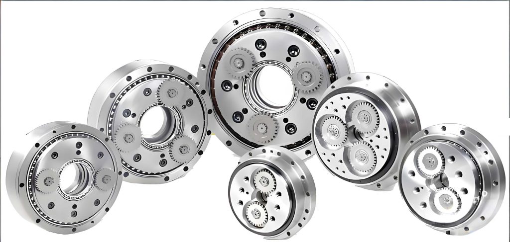
The rotary vector reducer achieves high reduction ratios through a two-stage mechanism: a primary planetary differential stage and a secondary cycloidal disc stage. In the planetary stage, a sun gear (input pinion) transmits power to three planet gears arranged at 120° intervals. Unlike a standard NGW planetary set, this stage lacks an internal ring gear. Each planet gear is internally splined and mounted onto a crankshaft. The eccentric portion of the crankshaft engages with the cycloidal disc, which meshes with stationary pins in the housing, creating the large speed reduction. The final output is taken from the planet carrier. This unique configuration grants the rotary vector reducer its renowned high torsional stiffness, compactness, and high precision.
The support structure is key to understanding the edge-loading problem. The input sun gear is typically supported by a single deep-groove ball bearing, allowing a degree of radial float to promote load sharing among the three planets. Conversely, each planet gear is mounted on its crankshaft in a cantilevered arrangement, with the crankshaft itself supported by two tapered roller bearings. This asymmetry in support stiffness is a fundamental contributor to misalignment.
The ideal condition assumes perfect geometry and assembly, where the three planet gears share the load equally, resulting in a net radial force of zero on the sun gear. However, manufacturing and assembly errors disrupt this ideal state. The primary sources of unequal load distribution in the planetary gear set of a rotary vector reducer are:
- Planet Carrier Bore Errors: Positional tolerance (true position) of the three crankshaft bearing bores and the parallelism/coaxiality error between the two bores for a single crankshaft axis.
- Planet Gear Phasing Error: Phase discrepancy between the external teeth and the internal spline of each planet gear. If three separate planets are used, their cumulative phasing error can be significant compared to grinding them as a stacked set.
- Spline Fit Clearance Variation: The internal spline of the planet gear and the external spline of the crankshaft have a clearance fit for assembly. Variations in manufacturing tolerance lead to different effective clearances for each planet gear, introducing additional phasing errors and radial play.
- Crankshaft Spline-to-Eccentric Phase Error: The angular relationship between the external spline (for the planet gear) and the eccentric journal (for the cycloidal disc) on the crankshaft is critical. Multi-step machining processes can introduce a phase deviation between these two features.
The superposition of these errors means the radial reaction forces from the three planet gears on the sun gear do not sum to zero. A net radial force $F_{radial}$ is generated on the sun gear, proportional to the input torque $T_{in}$:
$$
F_{radial} \propto \frac{T_{in}}{r_b}
$$
where $r_b$ is the base radius of the sun gear. This radial force, acting on the single-bearing-supported sun gear shaft, causes it to deflect. The deflection is maximal at the unsupported end (the mesh point), leading to a tilt. Consequently, contact occurs preferentially at the edge of the gear tooth face closest to the support bearing, while the opposite edge may experience little to no contact—a classic case of edge-loading or偏载接触. The effective load distribution factor $K_{H\beta}$ across the face width becomes significantly greater than 1, dramatically increasing the local contact stress at the loaded edge.
3. Modeling and Simulation of Load Distribution
To quantitatively assess the edge-loading problem and guide the improvement process, advanced gear contact analysis software is employed. The process involves creating a detailed digital twin of the planetary stage within the rotary vector reducer.
The modeling and analysis workflow is as follows:
- Geometry Import: Accurate 3D models of all components (sun gear, planet gears, carrier, crankshafts) are imported.
- Material & Stiffness Definition: Material properties (E, ν) and bearing stiffness matrices are defined.
- Mesh Generation: High-fidelity finite element meshes are generated for the gear teeth to resolve contact stresses.
- Error Incorporation: Realistic manufacturing tolerances (as listed in Section 2) are applied to the model to simulate “as-built” conditions.
- Load Case Definition: Operational loads corresponding to durability test conditions (e.g., 2.5x rated torque) are applied.
- Loaded Tooth Contact Analysis (LTCA): A non-linear contact analysis solves for the deformed state, contact pattern, load distribution, and stresses.
For a representative model of a rotary vector reducer (e.g., a 500 Nm class model) with typical manufacturing errors applied, the LTCA results before any corrective measures show a severe edge-loading condition. The contact pattern is concentrated at one corner of the sun gear tooth. The calculated parameters are summarized below:
| Component | Max Contact Stress $\sigma_H$ [MPa] | Face Load Factor $K_{H\beta}$ | Bending Safety Factor $S_F$ | Contact Safety Factor $S_H$ |
|---|---|---|---|---|
| Sun Gear (Input Pinion) | 1767 | 2.26 | 0.84 | – |
| Planet Gear | 1495 | 2.26 | 1.16 | – |
The results are alarming. The maximum contact stress on the sun gear (1767 MPa) far exceeds the allowable contact stress for typical case-hardened gear steel (approx. 1500 MPa). The high $K_{H\beta}$ value confirms severe uneven load distribution. Most critically, the bending safety factor $S_F$ for the sun gear is below 1.0, indicating a high risk of bending fatigue failure, let alone contact fatigue. This simulation validates the root cause analysis and quantifies the severity of the problem that leads to premature failure in the rotary vector reducer’s planetary stage.
4. Improvement Strategy: Targeted Gear Micro-Geometry Modification
To counteract the edge-loading caused by system deflection and errors, intentional modifications to the ideal involute tooth profile and lead crown are applied. This process, known as gear micro-geometry optimization or “修形,” aims to pre-compensate for the expected deflection under load, ensuring a more uniform pressure distribution across the entire active tooth surface. For the planetary gear set in a rotary vector reducer, a combination of profile and lead modifications proves most effective.
1. Profile Modification (Tip/Flank Relief): A parabolic crowning is applied along the profile direction (from root to tip). This relieves stress concentrations at the start and end of single-tooth contact zones and accommodates small pitch errors. The amount of relief $C_{\alpha}$ is typically in the range of 5-20 μm. The modified profile deviation $\delta_{pr}(s)$ from the ideal involute, as a function of the roll distance $s$, can be modeled as:
$$
\delta_{pr}(s) = C_{\alpha} \cdot \left( \frac{2(s – s_{mid})}{L_{\alpha}} \right)^2
$$
where $s_{mid}$ is the roll distance at the pitch point and $L_{\alpha}$ is the active profile length.
2. Lead Modification (Bias Crowning + Linear Taper): This is the crucial modification to correct edge-loading. A composite lead modification is applied:
- Linear Taper (Slope): A linear slope is introduced across the face width to counteract the angular misalignment (tilt) of the sun gear under the net radial load. The slope direction is chosen to add more material on the end that would otherwise separate, effectively “steering” the contact pattern towards the center.
- Lead Crowning: A parabolic crown is superimposed on top of the linear slope. This accommodates residual misalignment and ensures contact is contained within the face width even under varying loads. The total lead modification $\delta_{ld}(x)$ at a distance $x$ from the gear center along its axis is given by:
$$
\delta_{ld}(x) = S \cdot x + C_{\beta} \cdot \left( \frac{2x}{b} \right)^2
$$
where $S$ is the linear slope (μm/mm), $C_{\beta}$ is the lead crowning amount (μm), and $b$ is the net face width.
After applying optimized values for $C_{\alpha}$, $S$, and $C_{\beta}$ based on the LTCA results, the simulation is repeated. The improved contact pattern shows a well-centered, elliptical shape covering the majority of the tooth flank. The performance metrics show dramatic improvement, as shown in the comparative table below for two load cases.
| Condition & Component | 2.5x Rated Torque | 5.0x Rated Torque | ||
|---|---|---|---|---|
| Before | After | Before | After | |
| Sun Gear Contact Stress [MPa] | 1767 | 1244 | 2150* | 1580 |
| Planet Gear Contact Stress [MPa] | 1495 | 1052 | 1820* | 1340 |
| Face Load Factor $K_{H\beta}$ | 2.26 | 1.12 | 2.45* | 1.18 |
| Sun Gear Bending Safety $S_F$ | 0.84 | 4.75 | 0.65* | 3.81 |
| Transverse Contact Ratio $\epsilon_{\alpha}$ | 1.32 | 1.40 | 1.32 | 1.40 |
*Estimated from simulation trend.
The improvements are comprehensive. Contact stresses are reduced by approximately 30%, bringing them well within the material’s endurance limit. The face load factor $K_{H\beta}$ is reduced to near-ideal levels (close to 1.0), indicating excellent load distribution. The bending safety factors are increased substantially, eliminating the risk of root failure. Furthermore, the optimized micro-geometry slightly increases the effective transverse contact ratio, leading to smoother load sharing between successive tooth pairs and reduced transmission error.
5. Design Extension and Conclusion
The methodology outlined—root cause analysis via system error identification, quantitative assessment through high-fidelity LTCA simulation, and corrective action via targeted profile and lead modifications—forms a robust, closed-loop engineering process. This approach is not limited to a single model but is extensible to the entire family of rotary vector reducers. For different sizes in the N-series (e.g., 40N, 100N, 160N, 700N), the same principles apply. However, the specific optimal modification values ($C_{\alpha}$, $S$, $C_{\beta}$) must be recalculated for each configuration, considering its unique nominal load, gear geometry, bearing span, component stiffness, and realistic manufacturing tolerance stack-up. The final step is always the experimental validation of the modified design through standardized durability tests, with the results feeding back to fine-tune the simulation models for future iterations.
In summary, the planetary gear set, while not the final life-limiting component, plays a critical role in the overall durability of a rotary vector reducer. Its susceptibility to edge-loading contact fatigue, driven by inherent system deflections and manufacturing variances, generates destructive wear debris. By systematically applying gear micro-geometry optimization informed by detailed loaded contact analysis, the contact stress and load distribution can be dramatically improved. This not only enhances the direct fatigue life of the planetary gears but, more importantly, reduces the generation of abrasive particles, thereby protecting the downstream crankshaft and cycloidal components. This holistic improvement strategy is essential for advancing the performance and reliability of rotary vector reducers, contributing to the development of more durable and precise industrial robotics systems.