
In my research on industrial robotics, I have focused extensively on the rotary vector reducer, a critical component for precision motion control. The rotary vector reducer, often abbreviated as RV reducer, is a type of gearbox that provides high reduction ratios, compact design, and stable transmission, making it indispensable in applications such as medical machinery, agricultural equipment, and robotic arms. As one of the three core components of industrial robots, its reliability is paramount for system performance and longevity. In this article, I will delve into a comprehensive reliability analysis of the rotary vector reducer, incorporating modal analysis via finite element methods and failure mode evaluations to enhance its design and operational robustness.
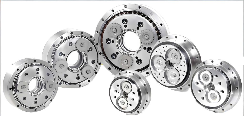
The rotary vector reducer operates through a two-stage reduction mechanism. The first stage involves the engagement of a sun gear and planetary gears, while the second stage utilizes a cycloidal pin wheel mechanism. These stages are connected by a crankshaft, enabling the high transmission ratios characteristic of rotary vector reducers. The key components include the sun gear, planetary gears, cycloidal gears, pin teeth, pin gear housing, and the crankshaft. Understanding the dynamic behavior and potential failure modes of these parts is crucial for improving the overall reliability of the rotary vector reducer.
To begin, I conducted a modal analysis on the crankshaft, which plays a pivotal role in transmitting torque and connecting the reduction stages. Using SolidWorks, I developed a detailed 3D model of the crankshaft and other primary components. This model was then imported into Ansys Workbench for finite element analysis. The material was specified as 45# steel, and a mesh was generated with 44,147 nodes and 29,511 elements to ensure accuracy. Constraints were applied at the bearing contact positions to simulate real-world conditions, with axial degrees fixed and tangential degrees free. The analysis settings limited the simulation to the first 10 natural frequencies and mode shapes, providing insights into the dynamic performance of the crankshaft within the rotary vector reducer.
The results of the modal analysis are summarized in the table below, which lists the natural frequencies and maximum displacements for each mode. These values are critical for avoiding resonance during operation, as resonance can lead to excessive vibrations and premature failure in rotary vector reducers.
| Mode Number | Maximum Displacement (mm) | Natural Frequency (Hz) |
|---|---|---|
| 1 | 128.48 | 0 |
| 2 | 600.2 | 17,203 |
| 3 | 601.67 | 17,209 |
| 4 | 122.14 | 20,244 |
| 5 | 114.89 | 22,606 |
| 6 | 121.95 | 22,669 |
| 7 | 459.29 | 29,915 |
| 8 | 371.55 | 38,263 |
| 9 | 157.91 | 43,773 |
| 10 | 216.77 | 44,800 |
From the mode shapes, I observed that the central portion of the crankshaft experiences significant deformation, while higher modes show maximum displacements at the planetary gear bore interfaces. This analysis underscores the importance of designing the crankshaft to avoid excitation at these natural frequencies, thereby enhancing the reliability of the rotary vector reducer. The natural frequency can be theoretically expressed using the formula for a simple beam model: $$ f_n = \frac{1}{2\pi} \sqrt{\frac{k}{m}} $$ where \( f_n \) is the natural frequency, \( k \) is the stiffness, and \( m \) is the mass. For complex geometries like those in a rotary vector reducer, finite element analysis provides more accurate results.
Moving beyond modal analysis, I employed Failure Mode and Effects Analysis (FMEA) to systematically evaluate potential failures in the rotary vector reducer. FMEA is a proactive method that identifies failure modes, their causes, effects, and preventive measures, which is essential for improving the reliability of rotary vector reducers. I focused on key components such as the cycloidal gear, pin teeth, pin gear housing, planetary carrier, and crankshaft. Each component was assessed for failure modes, with severity, occurrence, and detection ratings assigned to calculate the Risk Priority Number (RPN). The RPN helps prioritize issues for mitigation in rotary vector reducers.
For the cycloidal gear, common failure modes include static fracture, fatigue fracture, pitting, scuffing, wear, and plastic deformation. The table below outlines these modes, their impacts, causes, and preventive actions specific to rotary vector reducers.
| Failure Mode | Effect or Result | Cause | Preventive Measure |
|---|---|---|---|
| Static fracture (A1) | Complete failure | Overload, low strength | Use higher-strength materials, improve processing |
| Fatigue fracture (A2) | Complete failure | Excessive dynamic load, inadequate lubrication | Ensure proper lubrication, avoid overloading |
| Scuffing (A3) | Increased noise | Poor lubrication, high load | Enhance lubrication, improve precision |
| Pitting (A4) | Increased noise | Dynamic load, insufficient lubrication | Maintain lubrication, prevent overloading |
| Wear (A5) | Crack formation | Insufficient lubrication, low strength | Increase lubrication, select high-strength materials |
| Plastic deformation (A6) | Tooth profile deterioration | Dynamic load, poor lubrication | Lubricate adequately, avoid overloading |
The risk assessment for these failure modes in rotary vector reducers is quantified in the following table, which includes severity, occurrence, detection, and RPN values. This aids in focusing efforts on high-risk areas for rotary vector reducers.
| Failure Mode | Severity | Occurrence | Detection | RPN |
|---|---|---|---|---|
| A1 | 5 | 1 | 5 | 25 |
| A2 | 5 | 2 | 5 | 50 |
| A3 | 4 | 2 | 3 | 24 |
| A4 | 2 | 2 | 3 | 12 |
| A5 | 4 | 5 | 4 | 80 |
| A6 | 2 | 2 | 4 | 16 |
Similarly, I analyzed other critical components of the rotary vector reducer. For the pin teeth, failure modes include bending fracture (B1), housing cracks (B2), and pitting with cycloidal gears (B3). The pin gear housing may fracture due to overload, while the planetary carrier can crack under excessive pin tooth pressure. The crankshaft is prone to fracture or bending from stress concentration and misalignment. The FMEA table for these components in rotary vector reducers is presented below, highlighting key issues and solutions.
| Component | Failure Mode | Effect or Result | Cause | Preventive Measure |
|---|---|---|---|---|
| Pin Gear Housing | Fracture | Reducer failure | Severe overload | Replace material, improve processing, timely replacement |
| Planetary Carrier | Fracture | Vibration, noise, failure | Overload, high pin tooth pressure | Use better materials, enhance processing, improve installation accuracy |
| Crankshaft | Fracture | Reducer failure | Overload, stress concentration | Avoid prolonged overloading, adjust installation clearance |
| Crankshaft | Bending | Deformation, shaft failure | Improper installation, stress concentration | Increase installation precision, add lubrication |
The risk evaluation for these components in rotary vector reducers is summarized in the next table. The RPN values guide reliability improvements for rotary vector reducers by targeting high-priority failures.
| Component | Failure Mode | Severity | Occurrence | Detection | RPN |
|---|---|---|---|---|---|
| Pin Gear Housing | Fracture | 5 | 2 | 4 | 40 |
| Planetary Carrier | Fracture | 5 | 1 | 4 | 20 |
| Crankshaft | Fracture | 5 | 1 | 5 | 25 |
| Crankshaft | Bending | 4 | 3 | 4 | 48 |
To further enhance the reliability of rotary vector reducers, I investigated the manufacturing processes for key parts. Proper machining ensures dimensional accuracy and material integrity, reducing failure risks in rotary vector reducers. For the cycloidal gear, a multi-step process is employed, as detailed in the table below. This includes forging, heat treatment, grinding, and inspection to achieve the required properties for rotary vector reducers.
| Step Number | Process Name | Process Content |
|---|---|---|
| 1 | Precision Forging | Direct forging with machining allowance |
| 2 | Isothermal Annealing | Relieve residual stress, reduce hardness |
| 3 | Shot Blasting | Remove surface oxide layer |
| 4 | Carburizing and Quenching | Increase surface hardness and wear resistance |
| 5 | Tempering | Eliminate internal stress, minimize deformation |
| 6 | Rough Grinding | Grind end faces, tooth profiles, and bore |
| 7 | Finish Grinding | Final grinding of surfaces and bore |
| 8 | Surface Cleaning | Clean component surfaces |
| 9 | Inspection | Check accuracy, full inspection |
| 10 | Storage | Store in inventory |
For the pin gear housing, the machining process involves casting, turning, milling, drilling, and deburring. The table below outlines these steps, which are critical for maintaining the precision and durability of rotary vector reducers. Each step must be controlled to avoid defects that could compromise the rotary vector reducer’s performance.
| Step Number | Process Name | Process Content |
|---|---|---|
| 1 | Casting | Precision casting with 3 mm allowance per side |
| 2 | Heat Treatment | Normalizing and annealing |
| 3 | Shot Blasting | Remove oxide scale |
| 4 | Turning | Face right end |
| 5 | Rough Turning | Turn right outer diameter, leave 0.2 mm allowance |
| 6 | Finish Turning | Finish right outer diameter and length |
| 7 | Rough Boring | Bore right inner hole, leave 0.2 mm allowance |
| 8 | Finish Boring | Finish right inner hole diameter and length |
| 9 | Grooving | Cut inner groove |
| 10 | Turning | Face left end for total length |
| 11 | Rough Turning | Turn left outer diameter, leave 0.2 mm allowance |
| 12 | Finish Turning | Finish left outer diameter and length |
| 13 | Rough Boring | Bore left inner hole, leave 0.2 mm allowance |
| 14 | Finish Boring | Finish left inner hole diameter and length |
| 15 | Grooving | Cut left inner groove |
| 16 | Milling | Rough and finish mill external features |
| 17 | Milling | Rough and finish mill internal features |
| 18 | Drilling | Drill and ream 16-φ9 holes |
| 19 | Deburring | Remove burrs |
In addition to process control, I explored numerical control programming for machining the pin gear housing, using G-code to ensure accuracy. The code snippet below illustrates part of the program, which contributes to the precise manufacturing of rotary vector reducers. This attention to detail in machining is vital for the reliability of rotary vector reducers, as even minor deviations can lead to misalignment and increased wear.
N0010 G01 G90 X4.6457 Y0.0 U0.0 V0.0
N0020 X2.5591
N0030 X2.5512
N0040 G00
N0050 X4.6535
… (additional code lines as per the analysis)
The reliability of rotary vector reducers can also be analyzed through mathematical models. For instance, the probability of failure over time can be estimated using the Weibull distribution, which is common in reliability engineering. The failure rate function is given by: $$ \lambda(t) = \frac{\beta}{\eta} \left( \frac{t}{\eta} \right)^{\beta-1} $$ where \( \beta \) is the shape parameter, \( \eta \) is the scale parameter, and \( t \) is time. For rotary vector reducers, this model helps predict lifespan and plan maintenance schedules. Integrating FMEA results with such models enhances the predictive maintenance strategies for rotary vector reducers.
Furthermore, the stiffness of the crankshaft, which affects the transmission efficiency of rotary vector reducers, can be derived from beam theory. The torsional stiffness \( k_t \) is calculated as: $$ k_t = \frac{G J}{L} $$ where \( G \) is the shear modulus, \( J \) is the polar moment of inertia, and \( L \) is the length. In rotary vector reducers, optimizing this stiffness minimizes deformation under load, improving reliability. Modal analysis results align with this, as higher stiffness typically leads to higher natural frequencies, reducing resonance risks in rotary vector reducers.
Another aspect is the lubrication analysis for rotary vector reducers. Proper lubrication reduces friction and wear, extending component life. The film thickness in gear contacts can be estimated using the Elastohydrodynamic Lubrication (EHL) equation: $$ h = 2.65 \frac{(U \eta)^{0.7} R^{0.43}}{\alpha^{0.54} E’^{0.03}} $$ where \( h \) is the central film thickness, \( U \) is the rolling speed, \( \eta \) is the viscosity, \( R \) is the effective radius, \( \alpha \) is the pressure-viscosity coefficient, and \( E’ \) is the effective elastic modulus. For rotary vector reducers, maintaining adequate film thickness prevents direct metal contact, mitigating failure modes like pitting and scuffing.
In conclusion, my comprehensive analysis of rotary vector reducers highlights the importance of modal analysis and FMEA in enhancing reliability. By identifying natural frequencies and failure modes, designers can avoid resonance and address high-risk issues. Manufacturing processes must be meticulously controlled to ensure precision, and regular maintenance should include checks for overloading and lubrication. The rotary vector reducer’s performance hinges on these factors, and ongoing research into materials and design optimizations will further boost its reliability in demanding applications. As rotary vector reducers continue to evolve, integrating advanced simulation tools and reliability methods will be key to their success in industrial robotics and beyond.