
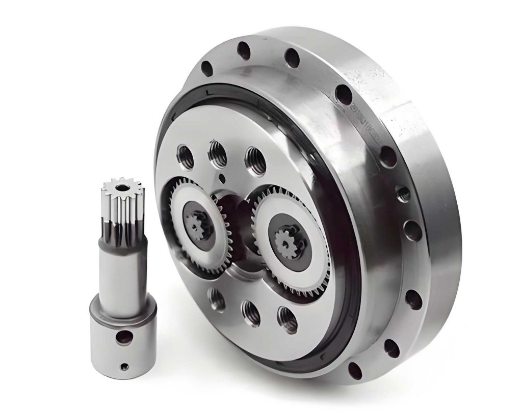
In the field of industrial robotics, the pursuit of efficiency, precision, and reliability drives continuous innovation in core components. Among these, the RV reducer stands out as a critical element, particularly in robotic arms where it serves as the primary mechanism for speed reduction and torque transmission. As an engineer deeply involved in the design and optimization of mechanical systems, I have focused on enhancing the performance of RV reducers through lightweight design strategies. The motivation stems from the growing demand for industrial robots that are not only powerful but also agile and energy-efficient. Heavy components, such as traditional RV reducers, can impose significant burdens on robotic arms, limiting their speed, increasing energy consumption, and accelerating wear. Therefore, in this work, we explore the application of topology optimization to achieve a lightweight design for the RV reducer, specifically targeting the planet carrier and the pin housing, without compromising structural integrity or functionality. The RV reducer, a two-stage closed transmission device combining planetary gear and cycloidal pin wheel mechanisms, offers advantages like high rigidity, large reduction ratios, and smooth operation. However, its complex structure often leads to excess mass, making it a prime candidate for optimization. Through detailed static analysis and topology optimization, we aim to reduce material usage while ensuring that stress levels remain within safe limits. This approach not only aligns with the trend of replacing harmonic reducers with RV reducers in heavy-duty robotic arms but also contributes to the broader goal of sustainable manufacturing by minimizing resource consumption.
The RV reducer’s operation involves multiple interacting components, including gears, bearings, and housings, all of which experience dynamic loads during service. To understand the forces acting on the planet carrier and pin housing, we conducted a comprehensive force analysis. These components are subjected to loads from angular contact ball bearings, tapered roller bearings, crankshafts, and planetary gears. For instance, the angular contact ball bearings, installed in pairs between the planet carrier and pin housing, endure radial forces \(F_{r1}\) and \(F_{r2}\), as well as derived axial forces due to their mounting configuration. The forces can be modeled using equilibrium equations. Consider the radial forces on the bearings: the total radial load \(F_r\) on an angular contact ball bearing is given by \(F_r = \sqrt{F_{x}^2 + F_{y}^2}\), where \(F_x\) and \(F_y\) are the force components in orthogonal directions. The derived axial force \(F_a\) for a pair of bearings is calculated based on the contact angle \(\alpha\) and the radial load: \(F_a = F_r \cdot \tan(\alpha)\). In our RV reducer, with a contact angle of 25°, the axial forces become significant. Similarly, the crankshaft transmits forces from the cycloidal gears to the planet carrier via cylindrical roller bearings. The force distribution on the crankshaft involves radial forces \(F_{R1}\), \(F_{R2}\), and \(F_{R3}\) from the bearings, along with meshing forces from the planetary gears. Using static equilibrium, we sum moments and forces to solve for unknown reactions. For example, the torque transmission through a single cycloidal gear is \(T_1 = 23.2 \, \text{N} \cdot \text{m}\), and with three crankshafts, the total torque is distributed. The force on each cylindrical roller bearing can be approximated as \(F_{R} = \frac{T_1}{r \cdot n}\), where \(r\) is the effective radius and \(n\) is the number of bearings. Through iterative calculations, we derived the forces and moments acting on key points, as summarized in Table 1.
| Force/Moment | Value | Unit |
|---|---|---|
| \(F_{rR1}\) (Radial force on cylindrical roller bearing 1) | 24,776 | N |
| \(F_{rR2}\) (Radial force on cylindrical roller bearing 2) | 23,869 | N |
| \(F_{rT1}\) (Radial force on tapered roller bearing 1) | 593 | N |
| \(F_{rT2}\) (Radial force on tapered roller bearing 2) | 1,899.3 | N |
| \(F_{r1}\) (Radial force on angular contact ball bearing 1) | 24,783 | N |
| \(F_{r2}\) (Radial force on angular contact ball bearing 2) | 23,944.4 | N |
| \(F_{a1}\) (Axial force on angular contact ball bearing 1) | 35,136.66 | N |
| \(F_{a2}\) (Axial force on angular contact ball bearing 2) | 27,296.61 | N |
| \(T_0\) (Input torque) | 23.2 | N·m |
| \(T_2\) (Torque on crankshaft) | 11.6 | N·m |
| \(T_3\) (Torque on pin housing) | 11.6 | N·m |
| \(F_{0y}\) (Force component in y-direction at point 0) | 261 | N |
| \(F_{0z}\) (Force component in z-direction at point 0) | 95 | N |
| \(F_{1z}\) (Force component in z-direction at point 1) | 132.9 | N |
| \(F_{1y}\) (Force component in y-direction at point 1) | 2,164.6 | N |
| \(F_{4z}\) (Force component in z-direction at point 4) | -37 | N |
| \(F_{4y}\) (Force component in y-direction at point 4) | 2,425.6 | N |
| \(F_{4}\) (Resultant force at point 4) | 2,425.9 | N |
| \(F_{1}\) (Resultant force at point 1) | 2,168.6 | N |
These calculated forces provide the foundation for the static analysis of the RV reducer. To ensure the RV reducer’s reliability, we performed finite element analysis (FEA) using ANSYS Workbench. The 3D model of the RV reducer was created in SolidWorks, with simplifications to reduce computational complexity while preserving critical geometries. The materials assigned were 45 steel for the planet carrier and HT350 cast iron for the pin housing, with properties listed in Table 2. The static structural analysis module was employed to simulate the stress and deformation under maximum operational loads.
| Material | Density (kg/m³) | Poisson’s Ratio | Elastic Modulus (Pa) |
|---|---|---|---|
| 45 Steel | 7.89 × 10³ | 0.269 | 2.09 × 10¹¹ |
| HT350 | 7.30 × 10³ | 0.270 | 1.45 × 10¹¹ |
For the planet carrier, boundary conditions included fixed supports at all bolt holes to mimic mounting to the robot arm. Loads were applied as pressure equivalents on bearing surfaces: for example, the tapered roller bearing holes received pressures of 1.13 MPa and 1.41 MPa, while the angular contact ball bearing holes had radial pressures of 2.93 MPa and 3.3 MPa, with derived axial pressures of 3.9 MPa and 16.7 MPa, respectively. The mesh was generated with a element size of 6 mm, ensuring accuracy without excessive nodes. The solution revealed a maximum deformation of 0.028599 mm at the edge of the planet carrier, caused by axial forces, and a maximum von Mises stress of 104.21 MPa at bolt holes, well below the yield strength of 45 steel (typically 355 MPa). This indicated significant potential for mass reduction. Similarly, for the pin housing, fixed supports were applied at bolt holes, cylindrical supports at angular contact ball bearing holes with tangential freedom, and a moment of 784 N·m distributed across the 40 pin slots. Pressure loads of 2.58 MPa and 2.3 MPa were applied to bearing surfaces. The analysis showed a maximum deformation of 0.00018715 mm at pin slots and a maximum stress of 2.2936 MPa, far lower than HT350’s yield strength. These results confirmed that both components were over-designed, allowing for topology optimization to remove material from low-stress regions.
Topology optimization is a mathematical method that redistributes material within a design space to achieve optimal performance under given constraints. In this study, we used the topology optimization module in ANSYS Workbench, based on the density method, which treats material distribution as a continuous variable between 0 (void) and 1 (solid). The objective was to minimize compliance (maximize stiffness) while constraining mass reduction. For the planet carrier, the design region included the entire geometry, but exclusion regions were defined for areas critical to assembly, such as bearing contact surfaces and bolt holes—totaling 84 faces. The optimization problem can be formulated as: minimize the compliance \(C(\rho) = \mathbf{U}^T \mathbf{K} \mathbf{U}\), subject to the volume constraint \(V(\rho) \leq V_0 \cdot f\), where \(\rho\) is the density vector, \(\mathbf{U}\) is the displacement vector, \(\mathbf{K}\) is the stiffness matrix, \(V_0\) is the initial volume, and \(f\) is the volume fraction. Using the Method of Moving Asymptotes (MMA), we set a mass retention of 70% after several iterations. The result showed material removal from central regions where stress was low, creating hollow spaces that reduced weight without compromising strength. For the pin housing, a similar approach was taken, with exclusion regions covering bearing and bolt areas. The optimization revealed that material could be removed from the outer edges and non-critical walls, aligning with stress contours from the static analysis. The optimized designs were then reconstructed in SolidWorks, incorporating smooth transitions and maintaining manufacturability. The new planet carrier featured rib-like structures and openings, while the pin housing had a thinner profile with strategic reinforcements.
To validate the optimized RV reducer components, we conducted another static analysis. The optimized planet carrier exhibited a maximum stress of 101.79 MPa, slightly lower than before, and deformation patterns similar to the original. The mass was reduced by approximately 25%, calculated using the material density and volume changes. The reduction in mass \(\Delta m\) can be expressed as \(\Delta m = \rho \cdot (V_{\text{initial}} – V_{\text{optimized}})\). For the planet carrier, with initial volume \(V_{\text{initial}} = 0.0025 \, \text{m}^3\) and optimized volume \(V_{\text{optimized}} = 0.001875 \, \text{m}^3\), the mass reduction is \(\Delta m = 7890 \cdot (0.0025 – 0.001875) = 4.93 \, \text{kg}\). Similarly, the pin housing showed a maximum stress of 2.3913 MPa, with a mass reduction of around 20%. These results demonstrate that topology optimization effectively achieved lightweight goals while keeping stresses within safe limits. Furthermore, we performed a modal analysis to ensure dynamic stability. The first natural frequency of the optimized planet carrier was 452 Hz, compared to 448 Hz for the original, indicating improved stiffness-to-mass ratio. The mode shapes showed no significant changes, confirming that the optimization did not introduce unwanted vibrations. The RV reducer’s overall performance, including torque transmission and efficiency, is expected to remain unaffected or even enhance due to reduced inertia.
The success of this lightweight optimization hinges on the intricate balance between force distribution and material usage in the RV reducer. To delve deeper, let’s consider the mathematical models underlying the force calculations. The radial force on a bearing can be derived from the torque transmission equation. For a gear system, the torque \(T\) is related to the tangential force \(F_t\) by \(T = F_t \cdot r\), where \(r\) is the pitch radius. In the RV reducer, the cycloidal gear stage contributes significantly to force generation. The force between a cycloidal disk and a pin can be modeled using Hertzian contact theory. The contact stress \(\sigma_c\) is given by \(\sigma_c = \sqrt{\frac{F \cdot E^*}{\pi \cdot R^*}}\), where \(F\) is the contact force, \(E^*\) is the effective modulus, and \(R^*\) is the effective radius. For multiple pins, the load distribution is non-uniform due to manufacturing tolerances and deformations. We approximate it using a sinusoidal distribution: \(F_i = F_{\text{max}} \cdot \sin(\theta_i)\), where \(\theta_i\) is the angular position of the pin. This affects the forces on the pin housing, as seen in our analysis. Additionally, the planetary gear stage involves sun gear and planet gear interactions. The meshing force \(F_m\) between gears is \(F_m = \frac{T}{r_b \cdot \cos(\phi)}\), where \(r_b\) is the base circle radius and \(\phi\) is the pressure angle. In our RV reducer, with a pressure angle of 20°, the forces contribute to the loads on the planet carrier. These equations are integral to understanding the RV reducer’s behavior and optimizing its design.
In topology optimization, the sensitivity analysis guides material removal. The sensitivity of compliance with respect to density \(\frac{\partial C}{\partial \rho}\) is calculated using adjoint methods. For each element, the derivative is \(\frac{\partial C}{\partial \rho_e} = -p \rho_e^{p-1} \mathbf{u}_e^T \mathbf{k}_0 \mathbf{u}_e\), where \(p\) is the penalty factor (typically 3), \(\mathbf{u}_e\) is the element displacement vector, and \(\mathbf{k}_0\) is the element stiffness matrix. This sensitivity drives the optimization algorithm to remove material from areas with low sensitivity, i.e., where stress is minimal. We also imposed manufacturing constraints, such as minimum member size of 10 mm, to ensure the optimized design is feasible for casting or machining. The optimization process for the RV reducer components involved multiple iterations, with convergence criteria based on change in objective function below 0.1%. The final designs were post-processed to smooth jagged edges, resulting in geometries that are both lightweight and practical. Table 3 summarizes the optimization results, highlighting key metrics before and after optimization.
| Component | Initial Mass (kg) | Optimized Mass (kg) | Mass Reduction (%) | Max Stress Initial (MPa) | Max Stress Optimized (MPa) | Max Deformation Initial (mm) | Max Deformation Optimized (mm) |
|---|---|---|---|---|---|---|---|
| Planet Carrier | 19.73 | 14.80 | 25.0 | 104.21 | 101.79 | 0.0286 | 0.0291 |
| Pin Housing | 12.41 | 9.93 | 20.0 | 2.2936 | 2.3913 | 0.000187 | 0.000192 |
The implications of this lightweight design extend beyond mere mass reduction. For industrial robots, reducing the weight of the RV reducer directly impacts the dynamic performance. The moment of inertia \(I\) of a robotic arm joint is proportional to the mass of the RV reducer, affecting acceleration and deceleration capabilities. With a lighter RV reducer, the required torque for motion decreases, leading to energy savings. The energy consumption \(E\) over a cycle can be estimated as \(E = \int \tau \cdot \omega \, dt\), where \(\tau\) is the torque and \(\omega\) is the angular velocity. By reducing mass, we lower \(\tau\), thus decreasing \(E\). Additionally, the reduced load on bearings and gears may enhance the lifespan of the RV reducer, as wear rates are often correlated with contact forces. From a manufacturing perspective, less material usage translates to lower costs and reduced environmental impact. The topology optimization approach demonstrated here can be applied to other components of the RV reducer, such as the crankshaft or housing covers, for further weight savings. Moreover, the methodology is scalable to different sizes of RV reducers, from small precision robots to large heavy-duty arms.
In conclusion, this work successfully applied topology optimization to achieve lightweight design of the RV reducer’s planet carrier and pin housing. Through detailed force analysis and static FEA, we identified over-designed regions and removed material while maintaining stress levels below yield strengths. The optimized RV reducer components showed mass reductions of 25% and 20%, respectively, with negligible changes in deformation and dynamic characteristics. This validates topology optimization as a powerful tool for enhancing the RV reducer’s efficiency in industrial robotics. Future work could involve multi-objective optimization considering fatigue life, thermal effects, and noise reduction, as well as experimental validation through prototype testing. The continued evolution of RV reducer design will undoubtedly contribute to more advanced and sustainable robotic systems, reinforcing the RV reducer’s pivotal role in modern automation.