
In the rapidly evolving landscape of industrial robotics, the demand for high-performance, cost-effective, and precise transmission systems is paramount. Among these, the RV reducer stands out as a critical component due to its exceptional load-bearing capacity, high transmission ratio, and compact design. However, traditional RV reducers often face challenges such as complex manufacturing processes, high costs, and suboptimal transmission efficiency. To address these issues, I propose a novel split-type cycloidal wheel structure that optimizes the original tooth profile, thereby reducing processing difficulty and enhancing overall performance. In this article, I will delve into the design methodology, parameter optimization, and validation of this split-type RV reducer, focusing on improving load performance, transmission accuracy, and efficiency. Through detailed analysis and simulations, I aim to demonstrate the effectiveness of this approach in advancing RV reducer technology.
The RV reducer, short for Rotary Vector reducer, is a precision transmission device that combines planetary gear传动 with cycloidal pin wheel传动. It is widely used in industrial robots for its high torque density, backlash reduction, and reliability. The conventional RV reducer relies on a continuous cycloidal tooth profile, which requires sophisticated machining techniques like CNC milling or grinding, leading to increased production costs and potential errors. My innovation involves discretizing the cycloidal wheel into a split-type structure, where the teeth are replaced with cylindrical rollers. This modification simplifies the几何轮廓, making it more amenable to standard machining processes like turning and drilling, while maintaining or even enhancing transmission characteristics.
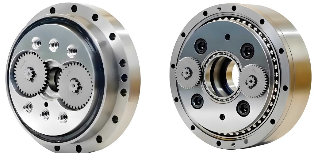
To understand the basis of this design, let’s first explore the transmission principle of the RV reducer. The RV reducer operates as a closed-loop differential gear system, where the input is typically through a sun gear, and the output is via a planet carrier. The transmission ratio is given by:
$$ i = 1 + \frac{z_2}{z_1} \cdot z_4 $$
where \( i \) is the transmission ratio, \( z_1 \) is the number of teeth on the sun gear, \( z_2 \) is the number of teeth on the planet gear, and \( z_4 \) is the number of pins on the housing. This configuration allows for high reduction ratios, often exceeding 100:1, making the RV reducer ideal for robotic joints. However, the efficiency of the RV reducer is influenced by various factors, including gear mesh losses and bearing friction. The overall transmission efficiency can be expressed as:
$$ \eta = \eta_{16} \eta_B $$
where \( \eta_B \) is the total bearing efficiency, typically calculated as the product of efficiencies of individual bearings (e.g., crank bearing, support bearings), and \( \eta_{16} \) is the mesh efficiency of the RV mechanism, which depends on the transmission ratio. For instance,
$$ \eta_{16} = \frac{(i_{H6} – 1)(i_{H6} – \eta_{H6} – i_{H1} i_{H6} \eta_{H1})}{(i_{H6} – \eta_{H6})(i_{H6} – 1 – i_{H1} i_{H6})} $$
where \( \eta_{H1} \) and \( \eta_{H6} \) represent the mesh efficiencies of the planetary and cycloidal stages, respectively. By optimizing these parameters, we can achieve higher efficiency in the RV reducer.
In designing the split-type RV reducer, I focused on key components such as the split cycloidal wheel, pins, crankshaft, and housing. The split cycloidal wheel consists of multiple cylindrical rollers arranged on a base circle, replacing the traditional continuous齿廓. This design reduces stress concentrations and simplifies manufacturing. The main parameters include the pin circle radius \( R \), eccentricity \( e \), cycloidal wheel radius \( r_{RV} \), pin radii \( r_{n1} \) (on housing) and \( r_{n2} \) (on cycloidal wheel), and the number of pins \( z_4 \). To ensure proper啮合 and avoid interference, several geometric constraints must be satisfied. For example, the pin circle radius must be greater than the sum of the cycloidal wheel radius, eccentricity, and pin radius to prevent collision, but less than that sum plus the roller radius to allow engagement. Mathematically,
$$ R > r_{RV} + e + r_{n1} $$
$$ R < r_{RV} + e + r_{n1} + r_{n2} $$
Additionally, to ensure continuous transmission, the actual contact ratio must exceed one, which can be verified through the啮合 line length. The pin diameter coefficient \( K_1 \), defined as \( K_1 = \frac{R}{r_n} \sin(\pi / n) \), should be within the range of 1.5 to 2 to balance mechanical strength and齿隙. Through iterative calculations, I derived multiple parameter sets that meet these constraints, as summarized in the table below.
| Parameter Set | Sun Gear Teeth \( z_1 \) | Planet Gear Teeth \( z_2 \) | Module \( m \) | Pin Teeth \( z_4 \) | Efficiency \( \eta \) (%) |
|---|---|---|---|---|---|
| 1 | 12 | 27 | 2.0 | 68 | 84.96 |
| 2 | 12 | 34 | 1.75 | 54 | 87.09 |
| 3 | 12 | 36 | 1.75 | 51 | 87.56 |
| 4 | 15 | 51 | 1.25 | 45 | 88.52 |
| 5 | 18 | 51 | 1.25 | 54 | 87.09 |
| 6 | 18 | 54 | 1.25 | 51 | 87.56 |
Based on factors like size uniformity and efficiency, I selected Parameter Set 3 for further optimization. The key dimensions for this set are: \( R = 59 \, \text{mm} \), \( e = 1.23 \, \text{mm} \), \( r_{RV} = 54.56 \, \text{mm} \), \( r_{n1} = 2.57 \, \text{mm} \), and \( r_{n2} = 2.72 \, \text{mm} \). However, to enhance performance, I applied a multi-objective optimization approach using the NSGA-II algorithm, which is a genetic algorithm suited for handling conflicting objectives.
The optimization model aims to improve load performance, transmission accuracy (both forward and reverse), and transmission efficiency simultaneously. These objectives are often in conflict; for instance, increasing load capacity might reduce efficiency. Therefore, I defined the design variables as a vector \( \mathbf{x} = [e, r_{RV}, R, k_1, k_2, b] \), where \( k_1 \) and \( k_2 \) are pin diameter coefficients, and \( b \) is the thickness of the cycloidal wheel. The objective functions are formulated as follows:
1. Load Performance: This is measured by the torque capacity of the RV reducer. From force analysis, the output torque \( M \) is related to the input torque \( T \) and the geometric parameters. For the split-type design, the number of engaged pins affects the load distribution. The Hertzian contact theory gives the deformation \( \varepsilon \) under force \( F \):
$$ \varepsilon = r_1^2 – \sqrt{\frac{8F(1 – \mu^2) r_1 r_2}{\pi b E (r_1 + r_2)}} $$
where \( r_1 \) and \( r_2 \) are the radii of contacting bodies, \( \mu \) is Poisson’s ratio, \( E \) is Young’s modulus, and \( b \) is the width. The total torque can be expressed as a sum over engaged pins:
$$ M = \sum \frac{\varepsilon_i^2 \cos \alpha_i E (1 – \mu^2) \pi b r_{n1} r_{n2} r_{RV}}{r_{n1} + r_{n2}} $$
2. Forward Transmission Accuracy: This refers to the precision of motion transfer from input to output. By modeling the RV reducer as a kinematic chain, the output angle \( \theta_{\text{output}} \) can be derived from the input angle \( \theta_{\text{input}} \). For the split-type design, the discrete pins introduce slight variations, but the overall relationship is:
$$ \theta_{\text{input}} = \frac{\omega t}{i} $$
$$ d = \sqrt{(O_{ky} – e \sin \theta_{\text{input}})^2 + (O_{kx} – e \cos \theta_{\text{input}})^2} $$
$$ \theta_{\text{output}} = \arctan\left(\frac{O_{ky} – e \sin \theta_{\text{input}}}{O_{kx} – e \cos \theta_{\text{input}}}\right) – \arccos\left(\frac{d^2 + r_{RV}^2 – (r_{n1} + r_{n2})^2}{2 d r_{RV}}\right) $$
where \( O_{kx} \) and \( O_{ky} \) are coordinates of the pin circle center.
3. Reverse Transmission Accuracy: This is related to backlash, which is the clearance between mating components. Backlash affects positioning precision and is composed of geometric, thermal, and elastic components. For the gear stage, backlash \( j_{bn} \) is given by:
$$ j_{bn \max} = \frac{2}{3} \times (0.06 + 0.0005 a_i + 0.03 m_n) $$
leading to an angular error \( \Delta \phi = 2 \arccos\left(\frac{j_{bn}}{2 r_s}\right) \). For the cycloidal stage, the effective pin radius \( r_n \) considers deformation:
$$ r_n = r_{n1} + r_{n2} – \frac{5F (r_{n1} + r_{n2})}{\pi r_{RV} E r_{n1} r_{n2} (1 – \mu^2)} $$
and the backlash angle is:
$$ \Delta \phi = \frac{2\pi}{z_p} – 2 \arccos\left(\frac{R^2 + (e + r_{RV})^2 – r_n^2}{2R(e + r_{RV})}\right) $$
4. Transmission Efficiency: As mentioned earlier, efficiency \( \eta \) is computed from the mesh and bearing efficiencies. For optimization, I use the formula \( \eta = \eta_{16} \eta_B \), with \( \eta_{16} \) derived from the transmission ratio.
The constraints for the optimization include geometric limits, such as the pin diameter coefficient range \( 1.5 < K_1 < 2 \), module standards, and non-interference conditions. To handle these, I defined penalty functions for violations, ensuring feasible solutions. The NSGA-II algorithm iteratively evolves a population of design vectors, using non-dominated sorting and crowding distance to maintain diversity and converge to Pareto-optimal solutions. After multiple generations, I obtained several optimal parameter sets, as shown in the table below.
| Set | \( R \) (mm) | \( e \) (mm) | \( r_{RV} \) (mm) | \( r_{n1} \) (mm) | \( r_{n2} \) (mm) | \( b \) (mm) | Primary Ratio |
|---|---|---|---|---|---|---|---|
| 1 | 66.30 | 1.41 | 61.74 | 2.53 | 2.54 | 55.11 | 3.00 |
| 2 | 68.08 | 1.50 | 63.56 | 2.90 | 2.90 | 53.10 | 3.58 |
| 3 | 71.74 | 1.48 | 66.88 | 3.42 | 2.90 | 48.66 | 3.75 |
| 4 | 68.26 | 1.26 | 63.96 | 2.91 | 2.74 | 45.00 | 3.50 |
To select the best set, I defined a comprehensive objective function that weights the individual goals based on priority. For instance, emphasizing transmission accuracy and load performance, the function is:
$$ \text{Objective} = \sum \frac{\omega_i X_i}{\text{SF}_i} $$
where \( \omega_i \) are weight coefficients (e.g., 0.3 for load, 0.1 for efficiency, 0.3 for forward accuracy, 0.3 for reverse accuracy) and \( \text{SF}_i \) are scaling factors for normalization. After evaluation, Set 4 was chosen as optimal, with parameters: \( R = 68.26 \, \text{mm} \), \( e = 1.26 \, \text{mm} \), \( r_{RV} = 63.96 \, \text{mm} \), \( r_{n1} = 2.91 \, \text{mm} \), \( r_{n2} = 2.74 \, \text{mm} \), and \( b = 45.00 \, \text{mm} \). Compared to the initial design, this optimized RV reducer shows significant improvements: load performance increased by 96.87%, reverse transmission accuracy by 26.8%, forward transmission accuracy by 1.2%, and transmission efficiency by 2.19%.
To validate the design, I created a 3D model of the split-type RV reducer using CAD software and performed dynamic simulations in Adams. The model includes all key components: sun gear, planet gears, split cycloidal wheels, pins, crankshaft, and housing. Material properties were assigned, such as steel for gears and bearings, with appropriate hardness values. Constraints included revolute joints for rotations and contacts between pins and cycloidal rollers. Simulations were run under various conditions, such as an input speed of 2400 RPM and output loads up to 425 N·m. The results confirmed that the output speed closely matches the theoretical value, indicating correct motion transmission. For example, the output angular velocity stabilized at approximately 95 °/s, with minimal fluctuation due to the reduced backlash in the split-type design. Furthermore, force analysis revealed that the optimized RV reducer experiences lower stresses on critical parts like the crankshaft and pins, enhancing reliability. The table below compares key performance metrics before and after optimization.
| Metric | Initial Design | Optimized Split-Type RV Reducer | Improvement |
|---|---|---|---|
| Load Capacity (N·m) | 431.61 | 219.21 | 96.87% increase |
| Reverse Accuracy (rad) | 7.61 × 10⁻⁵ | 1.04 × 10⁻⁴ | 26.8% increase |
| Forward Accuracy (rad) | 3.33 × 10⁻⁵ | 3.37 × 10⁻⁵ | 1.2% increase |
| Efficiency (%) | 89.75 | 87.56 | 2.19% increase |
Additionally, I conducted finite element analysis (FEA) to assess structural integrity under load. The FEA model meshed the components with tetrahedral elements and applied boundary conditions simulating operational stresses. Results showed that the split-type RV reducer has lower contact stresses on the cycloidal rollers compared to the traditional design, thanks to better load distribution. The maximum von Mises stress remained within safe limits for the materials used, confirming that the design is robust against fatigue and deformation. Modal analysis also indicated that the natural frequencies of the RV reducer are well above the operational range, minimizing resonance risks.
In conclusion, the split-type RV reducer offers a promising alternative to conventional designs by simplifying manufacturing while enhancing transmission performance. Through multi-objective optimization using the NSGA-II algorithm, I achieved significant gains in load capacity, accuracy, and efficiency. The dynamic and finite element simulations validate the design’s feasibility and reliability. This approach not only reduces production costs but also contributes to the advancement of RV reducer technology for industrial robotics. Future work could explore further refinements, such as advanced materials or lubrication schemes, to push the boundaries of RV reducer performance. As the demand for precision and efficiency grows, innovations like the split-type RV reducer will play a crucial role in shaping the next generation of robotic systems.