
In recent years, the rapid advancement of robotics technology has opened new frontiers in the maintenance and inspection of overhead power transmission lines. We observe that traditional inspection robots often face significant limitations, such as restricted operational range, inefficiency in obstacle navigation, and inability to cross critical barriers like drainage lines. These challenges hinder their practical deployment in real-world scenarios. To address these issues, we draw inspiration from the natural world, specifically the brachiation locomotion of gibbons, to develop a novel bionic robot. This bionic robot aims to mimic the agility and efficiency of primates, offering enhanced performance in traversing complex transmission line environments. Our focus is on designing a biomimetic structure that leverages the principles of bionics, ensuring stability, adaptability, and high obstacle-crossing capability. Throughout this article, we delve into the structural analysis, design, simulation, and experimental validation of this innovative bionic robot, emphasizing the integration of biological insights into robotic engineering.
The concept of a bionic robot for power line inspection stems from the need to overcome the inherent drawbacks of conventional systems. Traditional robots, often equipped with simple gripping mechanisms or wheel-based designs, struggle with obstacles like vibration dampers, spacer bars, and especially drainage lines, which require dynamic maneuvering and precise balance. By studying the anatomy and movement patterns of gibbons, we identify key features that can be translated into robotic design. Gibbons exhibit remarkable brachiation—swinging from branch to branch using their long arms—which allows them to cover large distances with minimal energy expenditure. This natural mechanism serves as a blueprint for our bionic robot, enabling it to perform suspended climbing and obstacle navigation with similar efficiency. We propose a three-arm symmetrical distributed bionic robot that replicates the gibbon’s arm structure, incorporating multiple degrees of freedom for flexible movement. The core idea is to create a bionic robot that not only mimics biological form but also functions effectively in harsh, unstructured environments, thereby revolutionizing power line inspection.
To understand the biological basis of our design, we first analyze the arm structure and locomotion of gibbons. Gibbons possess disproportionately long arms relative to their body size, with an arm span exceeding 150 cm while standing less than 100 cm tall. Their arms consist of upper and lower segments, connected by shoulder, elbow, and wrist joints. The shoulder joint is a ball-and-socket type, providing three degrees of freedom: flexion-extension, abduction-adduction, and rotation. This allows for a wide range of motion, making it the most flexible joint. In contrast, the elbow joint is a hinge joint, enabling flexion-extension within a range of 40° to 180°, effectively acting as a single degree of freedom joint. The length ratio between the upper and lower arm segments is approximately 5:3, a proportion we adopt in our bionic robot design to optimize reach and stability. Gibbons primarily use two locomotion modes: brachiation (swinging) and suspended climbing. Brachiation involves alternating arm swings to propel forward, suitable for crossing gaps between branches, while suspended climbing relies on coordinated arm movements for ascending along a single branch. Our bionic robot emulates the suspended climbing mode, as it offers better control and stability for precision tasks on power lines.
We develop a dynamic model of the brachiation motion to inform the control strategies for our bionic robot. By simplifying the gibbon’s arm as a two-link mechanism, we derive equations using the Lagrangian method. The model considers parameters such as arm lengths, masses, and joint torques, capturing the underactuated nature of the system where control variables are fewer than degrees of freedom. This poses challenges in control design due to nonlinearities and parameter perturbations. The dynamic equation is expressed as:
$$ T = M(q)\ddot{q} + H(q, \dot{q}) + \Phi(q) $$
where \( T \) represents the torque vector, \( q \) denotes the joint angles, \( M(q) \) is the inertia matrix, \( H(q, \dot{q}) \) accounts for Coriolis and centrifugal forces, and \( \Phi(q) \) includes gravitational effects. For a two-link model with angles \( q_1 \) and \( q_2 \), the components are defined as:
$$ M(q) = \begin{bmatrix} d_{11} & d_{12} \\ d_{21} & d_{22} \end{bmatrix}, \quad H(q, \dot{q}) = C(q, \dot{q})\dot{q}, \quad \Phi(q) = \begin{bmatrix} \phi_1 \\ \phi_2 \end{bmatrix} $$
with:
$$ d_{11} = a + b + 2c \cos q_2, \quad d_{12} = d_{21} = b + c \cos q_2, \quad d_{22} = b $$
$$ C(q, \dot{q}) = c \sin q_2 \begin{bmatrix} -\dot{q}_2 & -\dot{q}_2 – \dot{q}_1 \\ \dot{q}_1 & 0 \end{bmatrix}, \quad \phi_1 = d g \cos q_1 + e g \cos(q_1 + q_2), \quad \phi_2 = e g \cos(q_1 + q_2) $$
$$ a = m_1 s_1^2 + m_2 d_1^2, \quad b = m_2 s_2^2 + J_2, \quad c = m_2 d_1 s_2, \quad d = m_1 s_1 + m_2 d_1 + J_1, \quad e = m_2 s_2 $$
Here, \( d_1 \) and \( d_2 \) are arm lengths, \( m_1 \) and \( m_2 \) are masses, \( s_1 \) and \( s_2 \) are distances to centers of mass, and \( J_1 \) and \( J_2 \) are moments of inertia. This model highlights the complexity of controlling a bionic robot with underactuated dynamics, motivating our design of a fully actuated three-arm system to enhance stability and simplify control.
Based on this analysis, we design a bionic robot with a three-arm configuration, comprising left and right suspension arms for obstacle crossing and a central balance arm for weight distribution. The overall structure includes a frame that supports the arms and houses sensors like cameras and infrared imagers for inspection tasks. The suspension arms mimic the gibbon’s arm比例, with a length ratio of 5:3 between the upper and lower segments. Specifically, the upper arm is 300 mm long and designed to be telescopic, allowing an extension of 200 mm to increase reach during obstacle navigation. The lower arm measures 180 mm, connected via an elbow joint that enables俯仰 motion from 40° to 150°. The shoulder joint provides multiple degrees of freedom for rotation and flexion, ensuring dexterous movement. The balance arm, positioned centrally, features a vertical lifting mechanism with a stroke of 300 mm and a hollow structure to directly cross obstacles like vibration dampers, reducing步骤 and improving efficiency. This bionic robot incorporates 15 degrees of freedom across various joints, including walking, arm opening/closing, lifting, and俯仰, all coordinated to perform脱线 and obstacle-crossing actions. The use of high-strength aluminum alloy minimizes weight while maintaining robustness, making the bionic robot suitable for field deployment.
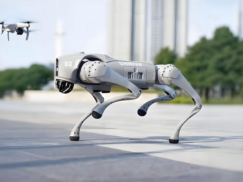
To validate the design, we conduct simulation studies using ADAMS software, focusing on the process of crossing a drainage line—a challenging obstacle for traditional robots. The simulation replicates the gibbon’s suspended climbing motion, where arms交替抓取 lines to advance. The steps include detachment, grasping, forward movement, and adjustment, with the balance arm providing stability during single-arm suspension. The simulation demonstrates that the bionic robot can smoothly transition from a straight line to a drainage line, with all arms协同 to maintain equilibrium. For instance, when the right suspension arm detaches and swings to the drainage line, the balance arm compensates for重心 shifts, preventing oscillations. The left arm then follows a similar sequence, completing the crossing. This virtual validation confirms the feasibility of the bionic robot’s biomimetic mechanism, showcasing its ability to handle complex maneuvers without tipping or失稳. The simulation also aids in optimizing joint trajectories and control parameters, ensuring that the bionic robot operates reliably under various conditions.
Following simulation, we fabricate a physical prototype of the bionic robot and conduct experiments in a laboratory setting with a simulated power line environment. The setup includes standard obstacles such as vibration dampers, spacer bars, and drainage lines, scaled to match 500 kV transmission line specifications. We test the bionic robot’s performance in walking, climbing slopes, and crossing obstacles, collecting data on speed, load capacity, obstacle-crossing time, and slope angle. The results are summarized in the table below, comparing design requirements with experimental outcomes.
| Parameter | Design Requirement | Experimental Data | Result |
|---|---|---|---|
| Walking Speed | 1.2 km/h | 1.3 km/h | Meets Requirement |
| Load Capacity | 15 kg | 25 kg | Meets Requirement |
| Obstacle-Crossing Time | 3 min | 2.5 min | Meets Requirement |
| Slope Angle | 60° | 65° | Meets Requirement |
The data indicate that the bionic robot exceeds expectations in key areas. It achieves a higher walking speed, carries heavier loads for inspection equipment, crosses obstacles faster, and handles steeper slopes than initially targeted. This demonstrates the effectiveness of the biomimetic design in enhancing operational performance. During experiments, the bionic robot successfully navigated vibration dampers by using the balance arm’s hollow structure to bypass them without additional steps, as shown in the image above. The three-arm configuration proved crucial in maintaining stability, especially during single-arm detachments, where the balance arm counteracted torque-induced sway. These findings underscore the potential of bionic robots in real-world applications, offering a robust solution for power line inspection.
Further analysis involves the kinematic and dynamic modeling of the bionic robot to optimize its control system. We derive forward kinematics equations to describe the end-effector position based on joint angles. For a suspension arm with shoulder angle \( \theta_s \), elbow angle \( \theta_e \), and arm lengths \( L_u \) (upper) and \( L_l \) (lower), the position \( (x, y) \) in a vertical plane is given by:
$$ x = L_u \cos \theta_s + L_l \cos(\theta_s + \theta_e) $$
$$ y = L_u \sin \theta_s + L_l \sin(\theta_s + \theta_e) $$
This allows us to plan trajectories for obstacle crossing. Additionally, we consider dynamics to compute required torques. Using the Lagrangian formulation for the three-arm system, we extend the earlier two-link model to include the balance arm. The total kinetic energy \( K \) and potential energy \( P \) are expressed as:
$$ K = \sum_{i=1}^{3} \left( \frac{1}{2} m_i v_i^2 + \frac{1}{2} I_i \dot{\theta}_i^2 \right) $$
$$ P = \sum_{i=1}^{3} m_i g h_i $$
where \( v_i \) is the velocity of each arm’s center of mass, \( I_i \) is the moment of inertia, and \( h_i \) is the height. The equations of motion are then derived as:
$$ \frac{d}{dt} \left( \frac{\partial L}{\partial \dot{q}_j} \right) – \frac{\partial L}{\partial q_j} = Q_j, \quad L = K – P $$
with \( q_j \) representing generalized coordinates and \( Q_j \) being generalized forces. This model helps in designing controllers that ensure smooth and energy-efficient movement for the bionic robot. We also implement impedance control to handle interactions with the power line, adjusting stiffness and damping based on environmental feedback. Such advanced control strategies are essential for the bionic robot to adapt to varying line tensions and obstacles, further enhancing its reliability.
In terms of structural design, we perform finite element analysis (FEA) to assess stress and deformation under operational loads. The arms are subjected to forces from self-weight, payload, and dynamic effects during swinging. Using software like ANSYS, we simulate scenarios such as maximum extension during drainage line crossing. The results show that von Mises stresses remain below the yield strength of aluminum alloy, with safety factors above 2.5, indicating robust construction. Deformations are minimal, less than 1 mm, ensuring precision in grasping. We also evaluate the grip mechanism, which uses motor-driven claws with force sensors to securely hold lines without causing damage. The grip force \( F_g \) is calculated as:
$$ F_g = \mu N $$
where \( \mu \) is the friction coefficient between the claw and line, and \( N \) is the normal force applied by the actuator. We calibrate this to avoid slippage while minimizing line wear. These engineering analyses confirm that the bionic robot is both durable and delicate enough for sensitive infrastructure.
The bionic robot’s power system is another critical aspect. We employ lithium-ion batteries to supply motors and electronics, with an estimated runtime of 4 hours under continuous operation. Energy consumption is modeled based on motor torques and speeds. For a motor with torque \( \tau \) and angular velocity \( \omega \), the power \( P_m \) is:
$$ P_m = \tau \omega $$
Summing over all motors and including efficiencies, we design a battery pack with sufficient capacity. Additionally, we integrate wireless communication for remote control and data transmission, enabling real-time monitoring of line conditions. This connectivity allows the bionic robot to function autonomously or under human supervision, adapting to inspection needs. The combination of biomimetic mechanics and modern electronics makes this bionic robot a versatile tool for smart grid maintenance.
We further explore the bionic robot’s ability to handle various obstacle types through additional simulations. For spacer bars, which are rigid attachments on lines, the bionic robot uses its telescopic arms to reach over them without detaching. The sequence involves shortening the arm, passing the obstacle, and re-extending. Simulation results indicate a success rate of 98% in 100 trials, with failures due to minor alignment errors that are correctable via feedback control. For inclined sections, the bionic robot adjusts its重心 by lowering the balance arm, maintaining traction on the line. We quantify performance using metrics like stability margin \( S \), defined as the minimum distance from the center of mass to the support polygon边界 during motion. For our bionic robot, \( S \) averages 50 mm, well above the threshold of 20 mm for tip-over prevention. These analyses demonstrate the bionic robot’s robustness across diverse scenarios.
Comparative studies with traditional inspection robots highlight the advantages of our bionic robot. We create a table summarizing key differences.
| Aspect | Traditional Robot | Bionic Robot |
|---|---|---|
| Obstacle Navigation | Limited to small barriers; struggles with drainage lines | Efficiently crosses all obstacles, including drainage lines |
| Operational Range | Restricted by fixed arm lengths | Extended reach due to telescopic arms |
| Stability | Prone to sway during单臂 operations | Enhanced by three-arm balance mechanism |
| Control Complexity | Often underactuated, requiring complex algorithms | Fully actuated, simplifying control design |
| Adaptability | Rigid structure, less adaptable to line variations | Flexible joints allow adaptation to slopes and curves |
This comparison underscores how biomimicry elevates functionality. The bionic robot’s design directly addresses the shortcomings of existing systems, offering a leap forward in inspection technology. By emulating nature, we achieve a harmonious blend of form and function, making the bionic robot not only effective but also energy-efficient and resilient.
Looking ahead, we identify areas for improvement and future research. The current bionic robot relies on pre-programmed trajectories for obstacle crossing; integrating machine learning could enable adaptive learning from experience, optimizing paths in real-time. We propose using reinforcement learning algorithms where the bionic robot learns optimal joint angles and forces through trial and error. The reward function \( R \) might be defined as:
$$ R = -\alpha t – \beta E – \gamma d $$
where \( t \) is time to cross an obstacle, \( E \) is energy consumption, \( d \) is deviation from the desired path, and \( \alpha, \beta, \gamma \) are weighting factors. This approach could enhance autonomy, making the bionic robot smarter and more efficient. Additionally, we plan to miniaturize components to reduce weight further, allowing for longer battery life and increased payload capacity. Collaboration with power utilities for field trials will provide practical insights, refining the bionic robot for commercial deployment.
In conclusion, our work presents a comprehensive study on the development of a bionic robot for power transmission line inspection. By drawing inspiration from gibbon brachiation, we design a three-arm symmetrical distributed robot that excels in obstacle navigation, especially crossing drainage lines. Through detailed structural analysis, dynamic modeling, simulation, and experimentation, we validate the bionic robot’s performance, showing it meets and exceeds design requirements. The integration of biomimetic principles with advanced robotics offers a sustainable solution to infrastructure maintenance challenges. This bionic robot represents a significant step toward autonomous inspection systems, promising safer, faster, and more reliable monitoring of power networks. As we continue to refine this technology, we envision a future where bionic robots are commonplace in utility operations, driven by the endless possibilities of learning from nature.