
As a researcher focused on robotic systems for hazardous environments, I have long been concerned with the persistent safety challenges in underground coal mining. The complex and often perilous conditions within mines pose significant risks to human workers, particularly during accidents where timely rescue is critical. Traditional inspection methods are limited in scope and safety, prompting the need for advanced technological solutions. In this work, I present the design and implementation of a bionic robot specifically engineered for the real-time safety survey of underground coal mine environments. This bionic robot leverages embedded systems, a variety of sensors, and robust mobility to navigate treacherous terrains, collect vital environmental data, and transmit it wirelessly to a surface control center, thereby enabling early warning and enhancing rescue capabilities.
The core philosophy behind this bionic robot is to create a mobile platform that mimics certain adaptive qualities of biological systems—hence the term ‘bionic’—while being engineered for extreme industrial environments. The bionic robot must be capable of autonomous or remotely piloted operation, reliable data acquisition, and resilient communication. The following sections detail the comprehensive design process, from theoretical framework and hardware integration to software architecture and functional validation. Throughout this discussion, the term ‘bionic robot’ will be frequently emphasized to underscore its bio-inspired yet technologically advanced nature.
1. Theoretical Framework and System Architecture
Designing an effective bionic robot for mine inspection begins with a clear theoretical model that separates hardware as the ‘body’ and software as the ‘mind’. I conceptualized the bionic robot’s architecture by defining interdependent modules that together enable its full functionality.
The hardware platform forms the physical embodiment of the bionic robot. It consists of several critical subsystems:
- Microcontroller Unit (MCU): The central processing ‘brain’ of the bionic robot, responsible for data processing, decision-making, and issuing control commands.
- Sensor Array: The sensory organs of the bionic robot, including modules for gas concentration (e.g., methane, carbon monoxide), temperature, humidity, barometric pressure, and visual perception.
- Locomotion Module: The limbs of the bionic robot, enabling movement across uneven and obstructed surfaces typical of mine galleries.
- Power System: The energy source, providing stable and regulated power to all electronic components, often with protection circuits for safety.
- Communication System: The nervous system, facilitating data exchange between the bionic robot and the remote operator station.
The software architecture imbues this hardware with intelligence. A modular approach was adopted, where specific firmware routines handle sensor data acquisition, motor control, communication protocols, and high-level task management. An embedded real-time operating system (RTOS) manages these concurrent tasks efficiently, ensuring responsive behavior of the bionic robot.
Based on this theory, the overall system design was broken down into five functional blocks, as summarized in the following table:
| Module | Primary Components | Function |
|---|---|---|
| Embedded Control | Main MCU (e.g., ARM Cortex-M), Secondary Motion Controller | Orchestrates all data processing, control logic, and task scheduling for the bionic robot. |
| Power Management | Lithium-polymer batteries, Voltage Regulators, Protection Circuits | Provides stable DC power to all subsystems and includes over-current/over-voltage protection. |
| Locomotion Drive | DC geared motors, Motor drivers (H-bridge), Track/Wheel assembly | Executes movement commands (forward, reverse, turn) enabling the bionic robot to traverse the mine. |
| Communication | Wi-Fi module (e.g., ESP8266/ESP32), Serial transceivers | Establishes a wireless link for telemetry data uplink and control command downlink. |
| Data Acquisition | Gas sensors (MQ-series), DHT22 (Temp/Humid), BMP180 (Pressure), CMOS Camera | Collects real-time environmental parameters and visual feeds from the bionic robot’s surroundings. |
The operational flow can be described by a high-level control equation. Let \( S(t) \) represent the state vector of the bionic robot at time \( t \), encompassing its position, sensor readings, and internal status. Let \( C(t) \) be the command vector from the remote operator. The bionic robot’s next state is governed by its control law \( F \):
$$ S(t+\Delta t) = F(S(t), C(t), E(t)) $$
where \( E(t) \) represents the environmental disturbances. The function \( F \) is implemented within the embedded software of the bionic robot.
2. Detailed Hardware Design and Implementation
The physical realization of the bionic robot required careful selection of components and design of electronic circuits to meet the demands of a dusty, humid, and potentially explosive atmosphere. My design prioritizes robustness, low power consumption, and modularity.
2.1. Overall Hardware System Layout
The hardware system integrates all modules around a central processor. Data from sensors flows into the MCU via serial communication buses (I2C, SPI, UART). The MCU processes this data and sends control signals to the motor drivers. Processed data and video streams are packetized and transmitted via the Wi-Fi module. A dedicated power distribution board ensures clean power rails. The schematic block diagram of the bionic robot’s hardware is shown below, illustrating these interconnections.
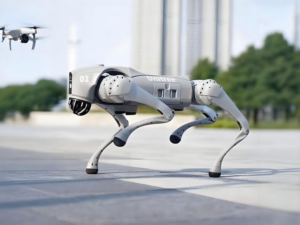
The image above provides a visual representation of the bionic robot’s chassis and sensor placement, highlighting its compact and rugged design suitable for confined mine spaces.
2.2. Circuit Design and Schematics
I designed the core circuitry for the bionic robot using standard electronic design automation tools. Key circuit blocks include the power supply, sensor interfaces, motor driver, and communication interfaces. The power supply circuit uses switching regulators (e.g., LM2596) to step down the battery voltage (e.g., 12V) to 5V and 3.3V for the MCU and sensors, respectively. Critical design equations for the regulator involve the output voltage \( V_{out} \) set by resistor dividers:
$$ V_{out} = V_{ref} \times (1 + \frac{R_1}{R_2}) $$
where \( V_{ref} \) is typically 1.23V for such regulators.
The motor driver circuit is based on a dual H-bridge IC (e.g., L298N), allowing bidirectional control of two DC motors. The power dissipation in the driver must be managed. The average current \( I_{avg} \) for a motor under load can be estimated, and the power loss \( P_{loss} \) in the driver is:
$$ P_{loss} = I_{avg}^2 \times R_{DS(on)} + \text{switching losses} $$
This informs heat sinking requirements for the bionic robot’s drive system.
Sensor interfaces are primarily digital. For analog sensors like certain gas detectors, the MCU’s internal ADC converts the signal. The resolution of the measurement is given by:
$$ \text{Resolution} = \frac{V_{ref}}{2^n} $$
where \( n \) is the ADC’s bit depth (e.g., 12 bits), and \( V_{ref} \) is the reference voltage. This determines the smallest detectable change in the parameter being measured by the bionic robot.
2.3. Chassis and Locomotion Design
The mobility of the bionic robot is paramount. After evaluating various mechanisms, I opted for a wheel-track hybrid system, which offers a bionic inspiration from creatures that adapt to both smooth and rugged terrain. This design combines the speed and efficiency of wheels on flat surfaces with the superior traction and obstacle-climbing ability of tracks on debris, slopes, and small gaps.
The chassis is fabricated from lightweight yet strong aluminum alloy. It features a main body housing the electronics, with two independent tracked units on either side. Each track is driven by a geared DC motor. A unique feature is a centrally mounted, servo-controlled rotating platform that holds the camera and some environmental sensors, allowing the bionic robot to pan its ‘head’ for a wider field of view without moving its body. The kinematics of the tracked vehicle can be simplified for control purposes. If the left and right track speeds are \( v_L \) and \( v_R \), the linear velocity \( v \) and angular velocity \( \omega \) of the bionic robot are:
$$ v = \frac{v_R + v_L}{2}, \quad \omega = \frac{v_R – v_L}{L} $$
where \( L \) is the distance between the centers of the two tracks. This model is used in the motion control algorithms for the bionic robot.
3. Software Architecture and Functional Realization
The intelligence of the bionic robot is encoded in its software. I developed a multi-layered software architecture running on the embedded MCU. The primary tasks are sensor data polling, motor control, image capture/compression, network communication, and command parsing.
3.1. Embedded Operating System and Task Management
To handle concurrency efficiently, I ported the FreeRTOS real-time kernel to the main MCU. This allows defining separate tasks for different functions. The task structure for the bionic robot is outlined below:
| Task Name | Priority | Function Description |
|---|---|---|
| Sensor_Task | Medium | Periodically reads all environmental sensors (gas, temp, humidity, pressure) and packages the data. |
| Motor_Control_Task | High | Receives velocity setpoints and executes PID control for the track motors. |
| Camera_Task | Medium | Controls the OV7670 camera module, captures image frames, and performs JPEG compression. |
| Comm_Task | High | Manages the Wi-Fi connection using the lwIP TCP/IP stack, sends telemetry and video packets, receives commands. |
| Supervisor_Task | Low (Idle) | Monitors system health (battery voltage, internal temperature) and can trigger safety shutdowns. |
The use of an RTOS ensures that critical tasks like motor control are not starved of CPU time, which is essential for the stable operation of the bionic robot.
3.2. Control Algorithms and Data Processing
For smooth movement, a Proportional-Integral-Derivative (PID) controller is implemented for each track motor. The control law for the motor speed is:
$$ u(t) = K_p e(t) + K_i \int_0^t e(\tau) d\tau + K_d \frac{de(t)}{dt} $$
where \( e(t) = \omega_{desired}(t) – \omega_{actual}(t) \) is the velocity error, and \( u(t) \) is the PWM duty cycle output to the motor driver. The gains \( K_p, K_i, K_d \) were tuned empirically during testing of the bionic robot.
Sensor data is filtered to reduce noise. A simple moving average filter is applied to analog readings. For a sensor value \( x \), the filtered output \( y_n \) at sample \( n \) over a window of size \( N \) is:
$$ y_n = \frac{1}{N} \sum_{i=0}^{N-1} x_{n-i} $$
This improves the reliability of the environmental data reported by the bionic robot.
Image data from the camera is compressed using a lightweight JPEG encoder before transmission to conserve bandwidth. The compression ratio \( CR \) is a key metric:
$$ CR = \frac{\text{Size of raw bitmap}}{\text{Size of JPEG file}} $$
A higher \( CR \) allows for more frequent image updates from the bionic robot within the same data rate.
3.3. Communication Protocol
A custom application-layer protocol was designed for communication between the bionic robot and the ground station. Data is sent as UDP packets for low latency, with TCP used for critical configuration commands. Each telemetry packet has a fixed structure containing sensor readings, bionic robot status (battery level, motor currents), and a sequence number. The packet structure can be represented as a byte array with defined offsets for each data field, ensuring efficient parsing by both the bionic robot and the ground station software.
4. System Integration, Testing, and Performance Evaluation
After assembling the hardware and flashing the firmware, rigorous testing was conducted to validate the performance of the bionic robot. Tests focused on communication range, sensor accuracy, mobility, and system endurance under simulated mine conditions.
4.1. Sensor Calibration and Accuracy Test
Each sensor on the bionic robot was calibrated against laboratory-grade instruments. For instance, the oxygen sensor was tested in a sealed chamber where the oxygen concentration was varied. The bionic robot’s readings were logged and compared to a calibrated gas chromatograph. The error percentage \( \epsilon \) for each measurement is calculated as:
$$ \epsilon = \left| \frac{V_{robot} – V_{ref}}{V_{ref}} \right| \times 100\% $$
A summary of the accuracy test for multiple parameters is presented in the table below.
| Parameter | Sensor Used | Reference Instrument | Average Error (%) | Notes |
|---|---|---|---|---|
| O₂ Concentration | Electrochemical sensor | Gas Chromatograph | ≤ 1.2% | Tested range 19-21% |
| Temperature | DHT22 | Calibrated Thermometer | ≤ 1.8% | Range 20°C to 35°C |
| Relative Humidity | DHT22 | Hygrometer | ≤ 2.5% | Range 30% to 80% RH |
| Methane (CH₄) | MQ-4 Semiconductor | Infrared Analyzer | ≤ 3.0% | Tested at 0.5% to 2% LEL |
The results confirm that the sensors integrated into the bionic robot provide sufficient accuracy for early hazard detection in a mining context.
4.2. Mobility and Obstacle Negotiation Tests
The bionic robot was tested on a constructed course mimicking mine debris: gravel, inclines up to 30°, and small gaps. Performance metrics such as maximum speed \( v_{max} \), climbable slope angle \( \theta_{max} \), and minimum turning radius \( r_{min} \) were recorded. The bionic robot successfully navigated all obstacles, demonstrating the effectiveness of the wheel-track design. The force balance for climbing a slope relates the motor torque \( \tau \) to the robot’s weight \( mg \), slope angle \( \theta \), and track-ground friction coefficient \( \mu \):
$$ \tau / r_{wheel} \geq mg \sin \theta + f_{rolling} $$
where \( r_{wheel} \) is the effective sprocket radius. The tested bionic robot met this criterion for the designed slope angles.
4.3. Endurance and Communication Range Test
The bionic robot’s operational time on a single battery charge was measured under typical load (sensors active, motors intermittently running, Wi-Fi transmitting). The total energy capacity \( E_{batt} \) (in Watt-hours) and the average power draw \( P_{avg} \) determine the endurance \( T \):
$$ T \approx \frac{E_{batt}}{P_{avg}} $$
With a 10Ah, 12V battery pack and an measured \( P_{avg} \) of 15W, the theoretical endurance is 8 hours. Practical tests yielded over 7 hours of continuous operation for the bionic robot.
The wireless communication range was tested in an open field and a simulated tunnel environment using standard Wi-Fi (2.4 GHz). The received signal strength indicator (RSSI) decays with distance \( d \) approximately as:
$$ \text{RSSI}(d) \approx \text{RSSI}(d_0) – 10 \cdot n \cdot \log_{10}(\frac{d}{d_0}) $$
where \( n \) is the path-loss exponent (higher in tunnels). The bionic robot maintained a stable link up to 150 meters in open space and 70 meters within a concrete-lined tunnel, which is adequate for most mine gallery inspections.
4.4. Integrated System Test with Ground Control Software
A dedicated ground control station (GCS) application was developed on a PC. This application displays real-time sensor data, video feed, and provides a virtual joystick for controlling the bionic robot. During integrated tests, an operator successfully piloted the bionic robot through the test course while monitoring live environmental data and video. All functions—movement, data acquisition, transmission, and alert generation (e.g., for high methane levels)—performed as designed. The latency \( \delta \) in the control loop, from joystick input to observable bionic robot movement, was measured to be under 200ms, which is acceptable for remote operation.
5. Discussion and Future Enhancements
The developed bionic robot prototype meets the core objectives of remote environmental inspection in underground mines. Its bio-inspired mobility, comprehensive sensor suite, and robust communication system make it a viable tool for pre-accident surveying and post-accident reconnaissance. The modular design allows for easy upgrades—for instance, adding LiDAR for 3D mapping or more sophisticated gas spectrometers.
However, certain limitations were identified. The current bionic robot relies heavily on remote teleoperation; integrating autonomous navigation algorithms would significantly enhance its utility. SLAM (Simultaneous Localization and Mapping) techniques could be implemented, requiring more computational power, perhaps via an onboard single-board computer alongside the MCU. Furthermore, the bionic robot’s ability to manipulate objects or deploy small payloads (e.g., life-saving equipment, communication relays) is not yet developed.
Future iterations of this bionic robot will focus on increased autonomy, advanced sensor fusion, and improved mechanical robustness for even harsher environments. The potential applications of such a bionic robot extend beyond mining to other hazardous industrial settings like chemical plants, disaster zones, and nuclear facilities.
6. Conclusion
In this project, I have detailed the complete design process of an embedded bionic robot for underground coal mine safety inspection. From the initial theoretical framework to the final integrated tests, every aspect was considered to create a reliable, functional, and adaptable machine. The bionic robot successfully demonstrates the capability to traverse difficult terrain, collect accurate environmental data in real-time, and relay that information to a safe location. By serving as a mechanical proxy for human inspectors, this bionic robot has the potential to drastically reduce human exposure to dangerous conditions, improve early warning systems for gas leaks or fires, and aid in rescue operations, thereby contributing to the overarching goal of enhanced industrial safety. The continued evolution of such bionic robots represents a critical step forward in leveraging technology to protect human life in extreme work environments.