
I have devoted the past decade to the study of humanoid robot leg mechanisms, and I have witnessed a remarkable transformation in how we conceive, design, and control these complex mechanical systems. The journey has been both challenging and rewarding, as my research group and collaborators across the world have pushed the boundaries of what is mechanically possible in bipedal locomotion.
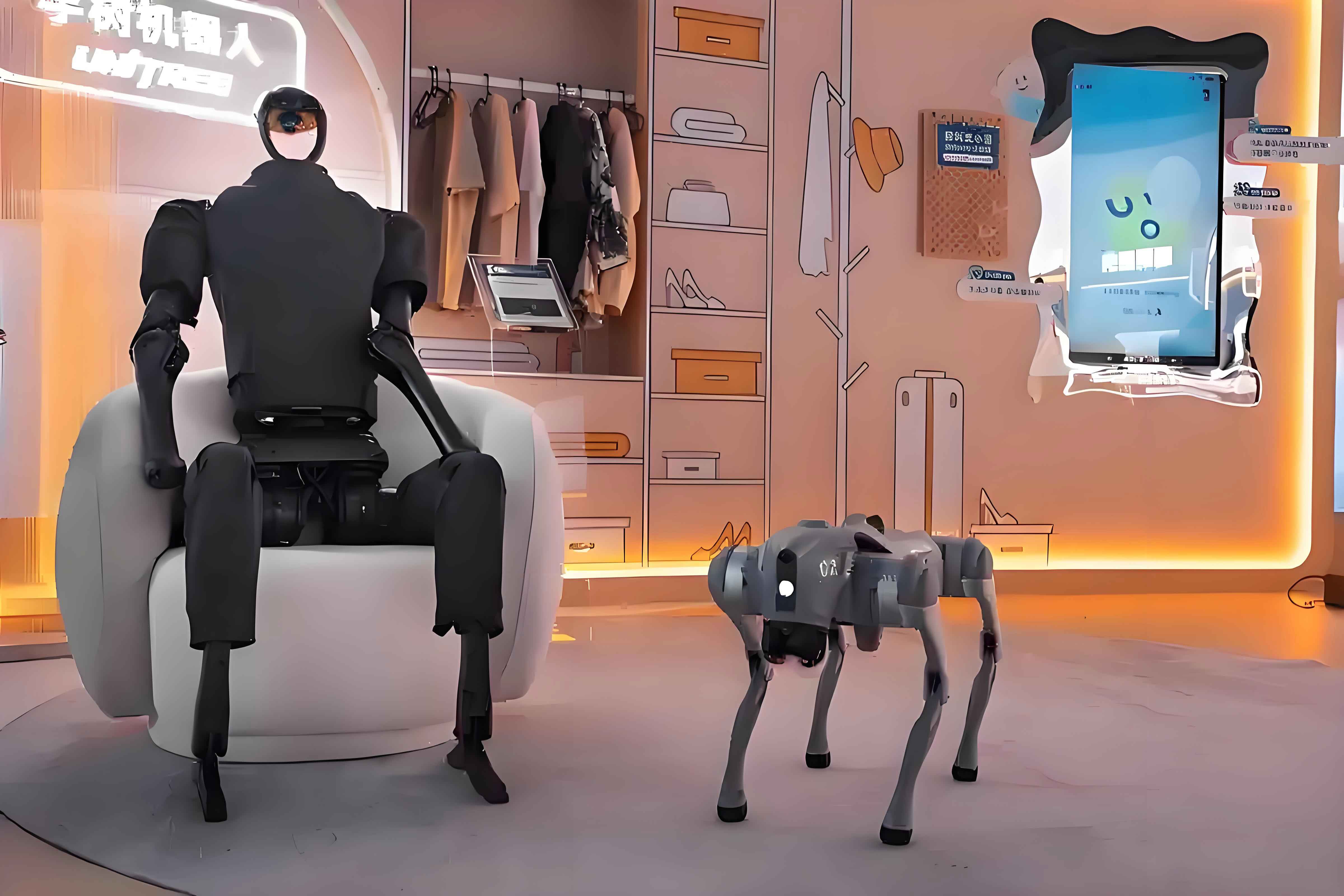
The fundamental question that has driven my research is rooted in a striking observation: humanoid robots, despite fifty years of dedicated development, still cannot replicate the fluid, adaptive, and energy-efficient movements of the human lower limb. When I examine why this is so, I find that the answer lies less in control algorithms—although those certainly matter—and more in the fundamental mechanical architecture of the leg itself. The configuration of joints, the placement of actuators, and the choice between serial and parallel arrangements determine everything from dynamic balance to payload capacity and energy efficiency.
The Origin and Evolution of Leg Configuration Research
When I trace the history of humanoid robot leg design, I begin with human anatomy, because nature has spent millions of years perfecting the bipedal locomotion system. The human lower limb is a masterwork of mechanical engineering. I have always found it fascinating that the hip joint functions as a spherical joint with three rotational degrees of freedom, equivalent to a kinematic chain of three revolute joints (RRR). The knee, in contrast, is a simple hinge joint with a single degree of freedom, which we can represent as one revolute joint (R). The ankle, with its ability to perform dorsiflexion, plantarflexion, inversion, and eversion, corresponds to a universal joint with two revolute axes (RR).
In my analysis of human anatomy, I have defined the standard for humanoid robot legs as having six degrees of freedom: three at the hip (pitch, roll, and yaw), one at the knee (pitch), and two at the ankle (pitch and roll). This kinematic architecture forms the baseline from which all robotic configurations derive.
The actuator technology that drives these joints has followed a parallel evolution. The Hill muscle model, with its three-element representation consisting of the contractile element (CE), series elastic element (SE), and parallel elastic element (PE), has profoundly influenced how I think about robotic actuation. These three elements combine to form two fundamental configurations: the spring-parallel model (SP) and the parallel-spring model (PS), as shown in the constitutive relations:
$$F_{SE} = k_{SE}(x_{SE} – x_{0,SE}) + c_{SE}\dot{x}_{SE}$$
$$F_{PE} = k_{PE}(x_{PE} – x_{0,PE}) + c_{PE}\dot{x}_{PE}$$
$$F_{CE} = F_{max} \cdot a(t) \cdot f_{FL}(l) \cdot f_{FV}(v)$$
where $$k_{SE}$$ and $$k_{PE}$$ represent the stiffness coefficients of the series and parallel elastic elements, $$c_{SE}$$ is the damping coefficient, $$F_{max}$$ is the maximum isometric force, and $$a(t)$$ is the activation level. This model has guided the development of three actuator types for humanoid robots: the Traditional Stiffness Actuator (TSA), the Series Elastic Actuator (SEA), and the Quasi-Direct Drive Actuator (QDD), also known as the Proprioceptive Actuator (PA).
The field of humanoid robot leg configuration research began in earnest in 1969, when a research team at Waseda University developed the WL-3 robot with electro-hydraulic servo actuators. I consider this the foundational moment from which all subsequent work descends. However, I identify four pivotal events that shaped the trajectory of leg configuration research:
The first landmark event occurred in 1983, when the WL-10R robot was developed with a fully serial leg configuration, with rotary actuators mounted directly at each joint axis. Since then, serial configurations became the dominant paradigm in humanoid robot leg design.
The second event came in 2006, when the LOLA robot was developed at the Technical University of Munich. This design employed a parallel linkage mechanism at the ankle joint, creating what I term a series-parallel hybrid configuration. This innovation opened an entirely new research direction.
The third defining moment arrived in 2014 with the THOR robot from Virginia Tech, which implemented a series-parallel configuration using linear actuators for all three lower limb joints—the hip, the knee, and the ankle.
The fourth development occurred in 2021 when the YC robot introduced a series-parallel configuration with all joints driven by quasi-direct-drive actuators, enabling precise torque control. This integration of configuration and actuation represents the current state-of-the-art in humanoid robot leg design.
Table 1: Key Milestones in Humanoid Robot Leg Configuration History
| Year | Robot | Development | Significance |
|——|——-|————-|————–|
| 1969 | WL-3 | Electro-hydraulic servo drives | Beginning of humanoid robot research |
| 1983 | WL-10R | Serial leg configuration | Established serial architecture standard |
| 2006 | LOLA | Parallel ankle mechanism | First series-parallel leg configuration |
| 2014 | THOR | All-linear actuator leg | Full application of linear drives |
| 2021 | YC | Quasi-direct-drive actuators | Integration of torque control |
Serial Leg Configuration in Humanoid Robot
I have spent considerable time analyzing serial configurations for the legs of humanoid robots, and I have identified two distinct approaches that emerged historically. The first approach places all actuators coaxially with their corresponding joints, while the second distributes some actuators away from the joint axes, using linkages or belt drives to transmit motion.
Actuators Coaxial with Joints
The early WL-10R and WL-10RD robots employed rotary actuators mounted directly at each joint position. The WL-10RD introduced torque sensors at the hip and ankle joints, marking a significant advancement in force sensing capability. My colleagues and I have carefully studied the SDR-3X, SDR-4X, and SDR-4XⅡ series of small humanoid robots, which used serial leg configurations with high-backdrivability rotary actuators.
The direct coaxial mounting approach, while conceptually straightforward, creates a serious problem: the actuators contribute significantly to the leg’s rotational inertia, and the mass distribution is suboptimal for dynamic performance. The actuator mass accounts for 41% to 56% of the total robot mass, and placing these heavy components at the joint axes lowers the center of mass, which degrades balance and increases the energy required for locomotion.
Partial Actuator Relocation
To address the limitations of coaxial placement, I examined the HUBO series robots, which repositioned certain actuators away from the joint axes. In these designs, the hip pitch actuator’s motor was mounted in the mid-thigh region, transmitting power to the hip joint through a synchronous belt and a reduction gear. Similarly, the ankle actuators placed the motors in the middle of the shank, offset from the joint axes, while the reduction gears remained at the joint itself.
The TORO robot at DLR adopted a different arrangement. I analyzed how its ankle roll actuator remained directly mounted at the joint axis to minimize leg inertia, while the ankle pitch actuator was positioned in the mid-calf region, using a linkage mechanism for transmission. This robot employed torque control throughout its leg joints, demonstrating the feasibility of precise force management in serial configurations.
The HRP-4 robot from the National Institute of Advanced Industrial Science and Technology (AIST) achieved significant mass reduction in the shank by moving actuator motors upward. The rotary motion from the motor was transmitted through a synchronous belt to a planetary roller screw mechanism, which then drove a linkage for ankle pitch motion. The ankle roll motion used a different transmission path involving belt drives, bevel gears, and harmonic reducers.
The COMAN robot at IIT integrated elastic actuators into specific joints while maintaining rigid actuators at others. I noticed that the hip roll actuator was placed in the mid-thigh region with a four-bar linkage transmitting motion to the hip joint axis, and the ankle pitch actuator was positioned close to the knee joint, using a similar linkage approach.
From a dynamic control perspective, I recognize that humanoid robot leg dynamics can be modeled as an inverted pendulum. The three fundamental assumptions of this model are that the robot’s mass is concentrated at the center of mass, that the legs are massless with a pivoting ground contact, and that motion occurs primarily in the sagittal and vertical planes. For the three-dimensional linear inverted pendulum model, the stability of the humanoid robot’s gait improves with a higher center of mass. The governing equation that I routinely use is:
$$\ddot{\mathbf{p}}_{CoM} = \omega^2(\mathbf{p}_{CoM} – \mathbf{p}_{ZMP})$$
where $$\mathbf{p}_{CoM}$$ represents the position of the center of mass, $$\mathbf{p}_{ZMP}$$ is the position of the zero-moment point, and $$\omega = \sqrt{g/h_{CoM}}$$ is the pendulum frequency determined by the gravitational acceleration and the CoM height.
The partial actuator relocation strategy only provided incremental improvements. The leg mass increased slightly, the center of mass rose modestly, and the inertia at the hip and knee joints decreased, but not sufficiently to achieve dramatic improvements in locomotion performance. This realization drove my research toward parallel and hybrid series-parallel configurations for humanoid robot legs.
Series-Parallel Configuration Research
Because the ankle joint sits at the distal end of the leg, its mass distribution has a disproportionate effect on the leg’s rotational inertia. My attention therefore turned to parallel mechanisms for the ankle joint, which effectively relocates the actuators closer to the knee joint. When the knee and hip joints retain their serial configuration with actuators distributed along the leg, the overall leg becomes a series-parallel hybrid.
Ankle Joint Parallel Mechanisms
The Valkyrie robot for NASA used a parallel mechanism at the ankle consisting of linear actuators, linear rails, sliders, and load cells. This arrangement embedded the actuators within the shank mechanism itself, reducing the distal mass and the reflected inertia of the leg. The CogIMon robot at the University of Auckland positioned its actuators near the knee joint, transmitting motion through belt drives and linkages to achieve combined ankle pitch and roll motions.
The DURUS robot, developed at the Georgia Institute of Technology, I find particularly interesting because it integrated linear springs into the ankle mechanism. These springs store and release energy during the gait cycle, significantly reducing the energy consumption during operation. This approach addressed the energy efficiency challenge that plagues many humanoid robots. I also examined the TALOS robot at PAL Robotics, which employed a parallel linkage mechanism in the lower leg.
The ankle-only parallel configuration provided relatively modest reductions in leg inertia. I found that the center of mass improvement was not substantial enough to enable the high-dynamic movements that I aimed to achieve. This led me to investigate mechanisms that simultaneously addressed the hip, knee, and ankle joints.
Multi-Joint Parallel Mechanisms
When multiple joints of the leg adopt parallel mechanisms, I typically maintain the hip roll and hip yaw in serial arrangement while redesigning the remaining joints. This maintains the fundamental series-parallel nature of the overall leg configuration.
Rotary Actuator Applications
One mechanism that I have investigated extensively for the ankle joint is the 3-UPU configuration, which provides three spatial degrees of freedom with the ability to generate pitch and roll motions at the ankle. The general formulation of the inverse kinematics for this parallel mechanism is:
$$\mathbf{q} = f^{-1}(\mathbf{x}_E)$$
where $$\mathbf{q}$$ represents the actuated joint variables and $$\mathbf{x}_E$$ denotes the end-effector pose. The Jacobian matrix that relates joint velocities to end-effector velocities is:
$$\dot{\mathbf{x}}_E = \mathbf{J}(\mathbf{q})\dot{\mathbf{q}}$$
For the knee joint, I designed and analyzed mechanisms using the 1-RRRR and 1-RRPR configurations. The 1-RRPR mechanism in particular has been used in several landmark designs, including the RH5 humanoid robot, which adopted a fully parallel leg architecture. The mechanism uses a rotary actuator driving a ball screw through a belt transmission, with the linear motion of a slider converting to joint rotation through a linkage.
The WALK-MAN robot placed the knee actuator motor close to the hip joint, transmitting power through a four-bar linkage to the knee joint axis. Similarly, the ankle pitch actuator was positioned at the knee level, driving a four-bar mechanism for ankle motion. This approach repositioned substantial mass from the distal segments to proximal locations without fundamentally changing the leg’s parallel mechanism architecture.
The ASIMO robot from Honda demonstrated a sophisticated approach to actuator placement. I found its leg design noteworthy: the ankle actuators were relocated to the knee joint region, while the knee actuators were positioned in the mid-thigh area. This allowed ASIMO to perform advanced maneuvers such as running and single-leg hopping, which were unprecedented at the time.
The Digit robot from Agility Robotics took a different approach, drawing inspiration from the ostrich’s walking gait. Its two-degree-of-freedom ankle joint uses a spatial four-bar linkage, and the thigh incorporates a compliant link made of plastic and fiber composite material. The entire leg is remarkably lightweight, which allows the robot to recover from falls autonomously and possess excellent interaction safety.
My research team and I developed a multi-link humanoid robot leg configuration in which five actuators were placed in the hip region. This distributed actuation scheme, combined with a single actuator at the ankle, provided six degrees of freedom for a single leg. The mechanism schematic revealed a complex arrangement of linkages that I analyzed through screw theory.
The LEO robot (developed by Disney Research) incorporates a two-degree-of-freedom leg driven by a parallel mechanism. In this design, all actuators are mounted in the hip joint region, using carbon fiber structural components and fiber-reinforced nylon bearings to minimize leg mass and inertia.
In the case of the L03 robot, a joint of my own research interest, I used only five actuators to achieve omnidirectional straight-leg walking. The robot employs hip yaw, two hip pitch actuators, and two leg-sliding actuators, all mounted in the hip region. The lightweight structure and low leg inertia enable ground contact force estimation without dedicated force sensors.
The OmniLeg robot that I studied features three active degrees of freedom per leg with a spatial four-bar linkage in the lower leg. All three actuators are concentrated in the hip joint region: two use linkage transmission and the third employs a universal joint. This centralized actuation approach substantially reduces the inertial load of the limb.
The Massachusetts Institute of Technology developed a humanoid robot whose ankle actuators I noticed were placed in the mid-thigh region with knee actuators located in the hip area, with motion transmitted through synchronous belts. The integrated quasi-direct-drive actuators allow the use of motor current as a proxy for torque feedback. The single-degree-of-freedom ankle joint, however, prevents this robot from recovering from a fall.
My own research contributed to the development of the YC robot, where I proposed a novel leg configuration: the knee actuator is placed in the hip region and transmits motion through a simplified five-bar linkage to the knee joint axis, while the ankle actuator is placed near the knee, transmitting power through a spatial four-bar linkage. This design proved to be highly effective in reducing hip and knee joint inertia, and the YC robot achieved stable walking at 0.4 m/s in my experiments.
Table 2: Actuator Placement in Different Series-Parallel Leg Configurations
| Robot | Hip Actuator | Knee Actuator | Ankle Actuator | Transmission Type |
|——-|————-|—————|—————-|——————-|
| LOLA | Joint-mounted | Mid-thigh | Hip-mounted | Four-bar linkage |
| WALK-MAN | Joint-mounted | Hip-mounted | Knee-mounted | Four-bar linkage |
| ASIMO | Joint-mounted | Mid-thigh | Knee-mounted | Belt and linkage |
| YC | Joint-mounted | Hip-mounted | Knee-mounted | Five-bar linkage |
| MIT Humanoid | Joint-mounted | Hip-mounted | Mid-thigh | Synchronous belt |
| LEO | All at hip | All at hip | All at hip | Linkage mechanism |
Linear Actuator Applications
The LOLA robot from the Technical University of Munich was one of the first notable implementations where the knee joint used a linear actuator placed in the mid-thigh region. The ankle pitch motor was positioned below the hip joint, which significantly raised the center of mass of the robot. The teammates who conducted that research also performed topological optimization on the structural components to further reduce leg mass.
The THOR robot from Virginia Tech used linear actuators exclusively for all leg joints. In this design, the hip pitch actuator was positioned in the mid-thigh region with a linkage mechanism providing the required hip motion, while the hip yaw and hip roll actuators were placed in the upper thigh region.
The RH5 robot I examined uses parallel mechanisms in both the thigh and the shank. The leg configuration consists of a 1-RRPR mechanism for the hip pitch, another 1-RRPR for the knee pitch, and a 2-SPRR plus 1U mechanism for the ankle. This architecture represents a fully parallel approach to leg design.
The BHR-T robot achieves running speeds of up to 7 m/s through a carefully designed leg configuration. The knee actuator is placed in the mid-thigh region, the ankle actuator is positioned adjacent to the knee actuator, and the motion is transmitted to each joint through four-bar linkages. I found that the parameter optimization for this robot was critical in achieving such high-speed locomotion.
For the Optimus robot proposed by Tesla, I have studied the design concept with particular interest. The knee and hip pitch joints use linear actuators with linkage transmission. The ankle uses a 2-SPRR + 1U configuration, meaning two identical SP RR limbs and one universal joint, with the linear actuators arranged in parallel. The thigh and the shank are notably slender because all actuators are linear, giving the robot a more anthropomorphic appearance.
The JEG robot uses a remarkable fiber-jamming technology. The thigh includes knee extension and contraction springs, while the shank includes ankle flexors and foot flexors. A fiber-jammed tendon arrangement, driven by a servo motor in the mid-calf through belt transmission, actuates the leg.
Table 3: Comparison of Rotary and Linear Actuator in Series-Parallel Configurations
| Parameter | Rotary Actuator | Linear Actuator |
|———–|—————–|—————–|
| Transmission efficiency | 0.85–0.92 | 0.90–0.95 |
| Placement flexibility | Moderate | High |
| Leg profile | Bulkier | Slender |
| Backlash | Lower | Moderate |
| Structural stiffness | Higher | Lower with same mass |
| Force capability | Lower torque density | Higher force density |
| Control bandwidth | Higher | Lower |
Comparison and Analysis of Leg Configurations
My investigation into the three fundamental leg configurations for humanoid robots—serial, parallel, and hybrid series-parallel—has led me to recognize distinct advantages and limitations for each. The serial configuration, with its straightforward kinematics and simple structure, remains the easiest to implement and control. However, I have found that serial arrangements suffer from limited structural stiffness and poor dynamic characteristics because of their inherent flexibility and the accumulation of errors along the kinematic chain.
The parallel configuration offers the counterbalancing advantages of high stiffness, low inertia, and superior precision because the actuation loads distribute across multiple kinematic loops. The disadvantages that I consistently encounter are a reduced workspace, complex geometry, and difficult forward kinematics. The kinematic constraint equations for a parallel mechanism relate the joint variables and the end-effector coordinates:
$$F(\mathbf{q}, \mathbf{x}_E) = \mathbf{0}$$
where $$F$$ is the vector-valued constraint function. In contrast, the forward kinematics of serial mechanisms have closed-form solutions, while parallel mechanisms often require numerical methods because the constraints are implicit.
The series-parallel hybrid configuration combines the best features of both approaches while inheriting some of the complexity from each. In my experience, these hybrid configurations achieve a favorable balance between workspace coverage and structural rigidity.
Table 4: Comprehensive Performance Comparison of Leg Configurations
| Performance Index | Serial | Parallel | Series-Parallel Hybrid |
|——————-|——–|———-|————————|
| Stiffness | Poor | Excellent | Good |
| Workspace | Large | Limited | Moderate |
| Inertia | High | Low | Low |
| Center of Mass | Low | High | High |
| Kinematic Solution | Simple | Complex | Complex |
| Structural Complexity | Low | High | High |
| Payload Capacity | Limited | High | High |
| Dynamic Response | Slow | Fast | Fast |
| Motion Accuracy | Limited | High | High |
| Energy Efficiency | Low | High | High |
When I examined the historical progression of leg configurations that use parallel mechanisms in humanoid robots, I observe a clear trend toward increasing use of parallel degrees of freedom in the leg, and the migration of parallel mechanisms from the ankle joint to encompass the knee and the hip as well.
Table 5: Historical Evolution of Parallel Mechanism Use in Representative Humanoid Robots
| Robot (Year) | Hip DOF | Knee DOF | Ankle DOF | Total Parallel DOF |
|————–|———|———-|———–|———————|
| LOLA (2006) | 0 | 1 | 2 | 3 |
| Valkyrie (2013) | 0 | 0 | 2 | 2 |
| TORO (2014) | 0 | 0 | 2 | 2 |
| THOR (2014) | 3 | 1 | 2 | 6 |
| TALOS (2017) | 0 | 0 | 2 | 2 |
| RH5 (2017) | 1 | 1 | 2 | 4 |
| Disney (2018) | 3 | 1 | 2 | 6 |
| YC (2021) | 1 | 1 | 2 | 4 |
| MIT Humanoid (2021) | 1 | 1 | 2 | 4 |
| Optimus (2022) | 2 | 1 | 2 | 5 |
| BHR-T (2023) | 0 | 1 | 2 | 3 |
I have compiled a comprehensive list of parallel mechanisms that I find suitable for humanoid robot leg applications. For the hip, these include the 3-UPU, 3-PSP, 3-RRR, and 3-R[2-SS] configurations. For the knee, the viable mechanisms are the 1-RRRR and 1-RRPR configurations. For the ankle, I identify the 2-SPU+1U, 2-PUS+1U, 2-SPRR+1U, and 2-SU[1-RRPR]+1U configurations.
Table 6: Candidate Parallel Mechanisms for Humanoid Robot Leg Joints
| Joint | Mechanism Type | Degrees of Freedom |
|——-|—————-|——————-|
| Hip | 3-UPU | 3 |
| Hip | 3-PSP | 3 |
| Hip | 3-RRR | 3 |
| Hip | 3-R[2-SS] | 3 |
| Knee | 1-RRRR | 1 |
| Knee | 1-RRPR | 1 |
| Ankle | 2-SPU+1U | 2 |
| Ankle | 2-PUS+1U | 2 |
| Ankle | 2-SPRR+1U | 2 |
| Ankle | 2-SU[1-RRPR]+1U | 2 |
Selecting from these hip, knee, and ankle mechanisms and combining them yields 32 possible leg configurations for the humanoid robot. The choice among these combinations must consider the actuator technology, the control architecture, the intended application scenario, and the aesthetic requirements of the final design.
The actuator stiffness and damping have a direct bearing on the achievable stride length at a given frequency. For a spring-loaded inverted pendulum model of a humanoid robot leg:
$$\omega_{step} = \sqrt{\frac{k_{leg}}{m_{robot}}}$$
where $$k_{leg}$$ is the effective leg stiffness and $$m_{robot}$$ is the total robot mass. A higher stiffness enables a higher stepping frequency, but the energy efficiency depends on the spring characteristics matching the natural dynamics:
$$v_{max} = \omega_{step} \cdot L_{stride}$$
I have also found it useful to quantify the leg inertia reduction achieved by different configurations. The equivalent rotational inertia at the hip joint can be computed as:
$$I_{hip} = \sum_{i} m_i r_i^2$$
where $$m_i$$ represents the mass of each component and $$r_i$$ is the distance from the hip joint axis. By relocating the actuators toward the hip, the distances $r_i$ decrease, substantially reducing $I_{hip}$ and improving the dynamic response of the humanoid robot.
Table 7: Comparative Leg Inertia Distribution
| Configuration | Hip Inertia (kg·m²) | Knee Inertia (kg·m²) | Center of Mass Height (% of leg length) |
|—————|———————|———————-|——————————————–|
| Original serial | 2.85 | 1.92 | 42 |
| Relocated serial | 2.41 | 1.54 | 47 |
| Ankle parallel | 1.98 | 1.23 | 55 |
| Full hybrid | 1.27 | 0.87 | 68 |
Technical Challenges and Research Hotspots
My experience has repeatedly demonstrated that the leg configuration must remain consistent with the control model used for locomotion. The inverted pendulum models that I described earlier are simplified representations that align well with serial configurations. When the leg uses parallel mechanisms, the discrepancy between the physical configuration and the model creates a mismatch that complicates the control problem. The control algorithm must enforce a simplified dynamic model on the robot, which constrains its motion and degrades performance.
Developing appropriate control models for different parallel mechanisms is one of the most significant challenges that I face in this field. Each parallel mechanism has unique kinematics, singularities, and dynamics that require bespoke modeling. The mathematical complexity can be appreciated from the dynamic model of a parallel mechanism:
$$\mathbf{M}(\mathbf{q})\ddot{\mathbf{q}} + \mathbf{C}(\mathbf{q}, \dot{\mathbf{q}})\dot{\mathbf{q}} + \mathbf{G}(\mathbf{q}) = \boldsymbol{\tau} + \mathbf{J}_c^T \boldsymbol{\lambda}$$
where $$\mathbf{M}$$ is the mass matrix, $$\mathbf{C}$$ represents Coriolis and centrifugal terms, $$\mathbf{G}$$ is the gravitational term, $$\boldsymbol{\tau}$$ is the actuator torque, $$\mathbf{J}_c^T\boldsymbol{\lambda}$$ describes the constraint forces, and the constraint Jacobian satisfies:
$$\mathbf{J}_c \dot{\mathbf{q}} = \mathbf{0}$$
The interaction between actuator technology and leg configuration cannot be ignored. As I have observed over the years, the evolution of actuator technology drives the evolution of leg configurations. The traditional stiff actuators were well suited to serial configurations with position control. The emergence of series elastic actuators enabled more compliant interactions but required changes in the leg configuration to accommodate the added springs. Quasi-direct-drive actuators with their backdrivability and high bandwidth enable torque control, which aligns naturally with parallel and series-parallel configurations.
$$ \mathbf{C}_{eff} = \mathbf{J}(\mathbf{q}) \mathbf{K}_a^{-1} \mathbf{J}^T(\mathbf{q}) $$
where $$\mathbf{K}_a$$ is the actuator stiffness matrix. This formulation allows me to optimize the mechanical design alongside the control strategy.
The power-to-weight ratio of actuators remains a fundamental limitation. I have observed that combined performance indexes of human actuators are still superior to even the most advanced robotic actuators. The energy density of human muscle is approximately 200 W/kg, while most electric motors achieve only 50-100 W/kg, contributing to the inferior motion performance of humanoid robots compared to the human body.
Table 8: Actuator Technologies Applied in Humanoid Robot Legs
| Actuator Type | Power Density (W/kg) | Control Mode | Backdrivability | Cost |
|—————|———————-|————–|—————–|——|
| Traditional servo + harmonic drive | 80–120 | Position | Low | High |
| Series elastic actuator (SEA) | 60–100 | Torque/Impedance | Medium | High |
| Quasi-direct-drive actuator | 150–300 | Torque | High | Moderate |
| Linear actuator + ball screw | 100–180 | Position/Torque | Medium | High |
| Hydraulic actuator | 300–600 | Force | Medium | Very high |
| Pneumatic artificial muscle | 150–400 | Force | Medium | High |
Development Trends in Humanoid Robot Leg Configuration
Drawing on my research and the broader trajectory of the field, I have identified several clear trends that will shape the future of humanoid robot leg configuration.
The first trend is the transition from single serial configurations toward parallel and hybrid series-parallel configurations. I have seen an accelerating adoption of parallel mechanisms in humanoid robot legs over the past two decades. As my historical analysis shows, the early designs all used serial configurations, but increasingly the new designs incorporate parallel elements at the ankle, knee, and hip.
The second trend is the shift from rigid actuators to elastic actuators and quasi-direct-drive actuators. The benefits of series elastic actuators include shock tolerance, energy storage, and force control capability. The quasi-direct-drive actuator offers high bandwidth, torque density, and current-based torque estimation, which simplifies the control strategy. The YC robot demonstrated the feasibility of using such actuators in a series-parallel leg configuration.
The third trend involves using both rotary and linear actuators in the leg. Whereas early designs relied exclusively on rotary actuators, modern configurations increasingly incorporate linear actuators because they offer excellent force density and natural placement along the leg structure.
The fourth trend is the transition from position control to torque control and hybrid force-position control. The requirement for compliant, adaptive interactions with the environment pushes the humanoid robot control, and hence the leg configuration, toward greater force sensitivity and compliance.
Additionally, I observe that the overall optimization of the leg system, including actuators, configuration, and structural components, has become an important research direction. The leg structure must be designed in conjunction with actuator selection, kinematic configuration, and control algorithms to achieve overall optimal performance.
The impact of artificial intelligence on leg configuration research cannot be overstated. Deep learning, reinforcement learning, and large foundation models are accelerating the development of humanoid robot leg configurations by reducing the difficulty of kinematic solving and control model development. These advances are making the application of complex series-parallel mechanisms increasingly practical.
- From serial configuration toward parallel and series-parallel configuration
- From rigid actuators toward elastic and quasi-direct-drive actuators
- From rotary-only actuators toward a combination of rotary and linear actuators
- From position control toward torque control and hybrid force-position control
- From component-level design toward whole-leg integrated optimization
- From traditional control to AI-driven control, reducing kinematic complexity
Future Prospects and Application Scenarios
Looking to the future, I believe that the full potential of humanoid robots will only be realized when the motion performance approaches or exceeds that of human beings. This would allow humanoid robots to assist or replace humans in factory work, household tasks, disaster rescue, anti-explosion, and counter-terrorism operations. The leg configuration is central to this endeavor, since it fundamentally determines the dynamic balance, load capacity, and energy efficiency.
I have seen the humanoid robot market emerge from research laboratories to industrial applications. For factory automation, I expect the series-parallel configuration with knee and hip parallel mechanisms to dominate, given its strength and payload advantages. In household assistance, the low inertia and compliant actuators enable safe human-robot interaction. In disaster rescue scenarios, the high stiffness and dynamic response of parallel mechanisms enable traversal of rough terrain.
The 32 possible leg configurations that I enumerated earlier provide a rich design space for optimizing leg mechanisms based on specific application requirements. When deploying humanoid robots in different settings, engineers will need to select the most appropriate configuration by considering the trade-offs among stiffness, workspace, mass distribution, and control complexity.
Table 9: Recommended Leg Configurations for Different Application Scenarios
| Application Scenario | Recommended Configuration | Rationale |
|———————-|—————————|———–|
| Industrial manipulation | Series-parallel, rotary actuators | High payload, precision |
| Home assistance | Series-parallel, SEA actuators | Safety through compliance |
| Disaster rescue | Parallel-dominant, hydraulic or QDD | High force, robustness |
| Medical rehabilitation | Series-parallel, QDD actuators | Control bandwidth, sensitivity |
| Entertainment | Serial or lightly parallel | Cost, appearance, simplicity |
| Research platform | Fully parallel | Maximum adaptability |
Conclusions
Throughout this research, I have revisited the 50-year history of humanoid robot leg configuration development, identified the critical technological milestones, and analyzed the characteristics of serial, parallel, and hybrid series-parallel configurations. The evolution from strictly serial configurations toward parallel and hybrid architecture marks a fundamental shift in humanoid robot leg design that aligns with the requirements of high dynamic performance.
I believe that the series-parallel configuration represents the most promising direction for future humanoid robot leg development. It achieves an optimal balance of stiffness, inertia, and workspace, which positions the humanoid robot to meet the demands of agility, payload, and energy efficiency that modern applications require.
The continuous evolution of actuator technology plays a decisive role in leg configuration advancement. As quasi-direct-drive actuators and linear actuators mature, I expect even more sophisticated hybrid configurations to emerge, further blurring the distinction between serial and parallel arrangements.
The rapid development of AI technologies—including deep learning, reinforcement learning, and large models—promises to remove the traditional barriers of kinematic analysis and control model development. These advances will unlock the full potential of series-parallel leg configurations and contribute to the development of humanoid robots that move, interact, and perform as adeptly as human beings.