
In recent decades, robotics research and development have been predominantly focused on industrial manipulators, while service robots have received relatively less attention. As living standards continue to rise, an increasing number of service robots are expected to enter human daily life, performing tasks in areas such as housekeeping, entertainment, education, and reception. Unlike pure task-oriented machines, service robots that can achieve natural human-robot interaction and emotional communication are far more appealing. Psychological studies indicate that more than 60% of human communication is non-verbal, including facial expressions, gaze, and gestures. Therefore, the development of a humanoid robot head that can replicate basic facial and head motions becomes essential for enhancing the acceptability and effectiveness of service robots.
This thesis focuses on the design and optimization of a humanoid robot head for a mobile service robot platform. The work covers the complete head system, including mechanical design, control architecture, and software interface, as well as two advanced theoretical optimizations: the reduction of driving torque through compliant joints, and the suppression of vibration through link shape optimization. The results are verified through both simulation and prototype experiments.
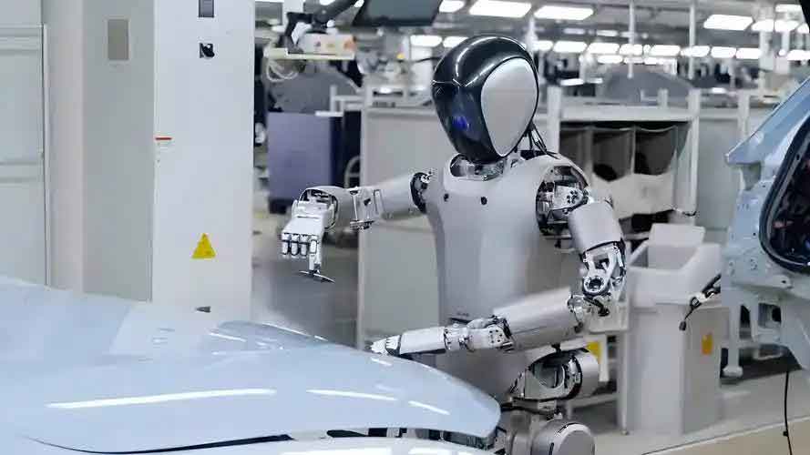
1. System Architecture of the Humanoid Robot Head
The overall humanoid robot head system consists of a mechanical structure, an industrial PC, a control computer, a wireless network card, a camera, and servo motor controllers. The system is designed to fit inside a mobile stage robot, allowing wireless remote control. An operator sends commands from a remote computer through a wireless network to the onboard industrial PC, which then communicates with the servo controller board to command the servo motors, thus achieving the desired motions. Simultaneously, the camera captures video information and transmits it back to the operator through the industrial PC.
The mechanical structure is designed to realize the following basic actions: blinking of the eyelids, rotation of the eyeballs in both horizontal and vertical directions, opening and closing of the lower jaw, and nodding and shaking of the head. In total, six degrees of freedom are required. The correspondence between the actions and degrees of freedom is summarized in Table 1.
| Position | Motion | Number of DOFs |
|---|---|---|
| Eyelid | Blinking | 1 |
| Eyeball | Vertical rotation | 1 |
| Eyeball | Horizontal rotation | 1 |
| Lower jaw | Open/close | 1 |
| Neck | Nodding | 1 |
| Neck | Shaking | 1 |
Because the internal space inside the head is extremely limited, linkage mechanisms are preferred to direct gear drives. Each actuator can drive both eyes simultaneously, which greatly simplifies the structure and reduces the required number of motors.
1.1 Blinking Mechanism
The blinking motion is realized by a swinging guide-bar mechanism, as shown schematically in Figure 1. Here, motor drives link 1, which rotates from 120° to 240°. Through a sliding pin, link 2 oscillates within the range of –30° to 30°. The eyelid is attached to link 2, and the rotation of link 2 creates the blink motion. The geometric parameters are given in Table 2.
The relation between the input angle \(\theta_1\) and the output angle \(\theta_3\) is established through the geometry of the mechanism. In the diagram, \(l_0\) is the fixed base length, \(l_1\) is the driving link length, \(l_2\) is the follower link length, and \(d_2\) is the sliding distance. The following constraint equations hold:
$$ d_2 \cos\theta_3 = l_0 + l_1\cos\theta_1 $$
$$ d_2 \sin\theta_3 = l_1\sin\theta_1 $$
By eliminating \(d_2\), the expression for \(\theta_3\) as a function of \(\theta_1\) is derived. The angular velocity and acceleration of the follower link are then obtained by differentiating the geometric relation with respect to time.
| Parameter | Value |
|---|---|
| \(\theta_1\) range | 120° – 240° |
| \(\theta_3\) range | –30° – 30° |
| \(l_0\) | 80 mm |
| \(l_1\) | 40 mm |
1.2 Horizontal Eye Movement Mechanism
The horizontal movement of the eyes is realized by a parallelogram four-bar linkage. Link 1, link 3 and link 4 always remain parallel. The motor drives link 1, and the motion is transmitted through link 2 to links 3 and 4, which are rigidly attached to the eyeballs. Consequently, the eyeballs rotate horizontally with exactly the same angle and velocity as the driving link. The geometric parameters are listed in Table 3.
| Parameter | Value |
|---|---|
| \(l_1, l_3, l_4\) | 40 mm |
| \(l_2\) | 80 mm |
1.3 Vertical Eye Movement Mechanism
The vertical movement of the eyes is achieved by a four-bar linkage. The motor drives the crank (link 1), which transmits motion through the coupler (link 2) to the rocker (link 3). The rocker is rigidly connected to the eyeball, so the rotation of link 3 causes the eyeball to rotate vertically. The following geometric constraints are used to determine the unknown lengths:
$$ l_1\cos q_1 + l_2\cos q_2 = l_0 + l_3\cos q_3 $$
$$ l_1\sin q_1 + l_2\sin q_2 = l_3\sin q_3 $$
The design requires that when \(q_1 = 45^\circ\), \(q_3 = 60^\circ\), and when \(q_1 = 135^\circ\), \(q_3 = 120^\circ\). Substituting these two sets of values into the loop equations yields the unknown lengths \(l_2\) and \(l_3\). The computed parameters are summarized in Table 4.
| Parameter | Value |
|---|---|
| \(q_1\) range | 45° – 135° |
| \(q_3\) range | 60° – 120° |
| \(l_1\) | 40 mm |
| \(l_2\) | 63.5 mm |
| \(l_3\) | 56.6 mm |
| \(l_0\) | 60 mm |
2. Control and Software
All six degrees of freedom are driven by servo motors. Servo motors are chosen because they are lightweight, compact, low-cost, and easy to control, especially when high precision and large torque are not required. The servo controller is based on the Arduino development platform and is connected to the industrial PC via a USB interface. The controller can drive up to 32 servo channels, which is sufficient for the six motions of the head.
A graphical user interface was developed using Visual C++ and the MFC framework. The interface allows the operator to select the serial port, establish communication, set the initial neutral position, and individually control each joint through either push buttons or slider bars. For example, clicking the “Blink” button executes the predetermined blink motion, while dragging the “Eyelid” slider moves the eyelid to any arbitrary position within its working range. The interface also displays video feedback from the onboard camera.
3. Driving Torque Reduction Using Compliant Joints
Since the humanoid robot head is installed on a mobile service robot powered by an internal battery, reducing energy consumption is an important design objective. One effective method is to introduce passive compliant elements, such as springs, into the joints of the linkage mechanisms. In this study, compliant joints are applied to two representative mechanisms: the swinging guide-bar mechanism (for blinking) and the parallelogram mechanism (for horizontal eye movement). The goal is to optimize the spring parameters so that the required driving torque of the motors is minimized over the entire desired motion trajectory.
3.1 Modeling of the Swinging Guide-Bar Mechanism with Compliant Joints
A schematic of the compliant mechanism is shown in Figure 2. Three springs are added: a torsion spring at joint 1, a linear spring at joint 2, and a torsion spring at joint 3. The spring torques/forces are functions of the joint positions:
$$ \tau_{s1} = k_1(\theta_1 – \delta_1) $$
$$ f_{s2} = k_2(d_2 – \delta_2) $$
$$ \tau_{s3} = k_3(\theta_3 – \delta_3) $$
where \(k_i\) represents stiffness and \(\delta_i\) is the initial position. The dynamic equations are derived using the Newton-Euler method. Considering the free-body diagrams of link 1 and link 2, the following matrix equation is obtained:
$$ \mathbf{M} \mathbf{R} = \mathbf{B}_1 – \mathbf{B}_2 $$
where \(\mathbf{R}\) is the vector of unknown reaction forces and the driving torque \(\tau_1\), \(\mathbf{M}\) is the coefficient matrix, and \(\mathbf{B}_1\), \(\mathbf{B}_2\) contain the inertial and external terms. The derivation ensures that the relation between the angular position, velocity, and acceleration of the driving link and the driven link is correctly incorporated through the kinematic constraint equations.
3.2 Modeling of the Parallelogram Mechanism with a Compliant Joint
For the parallelogram mechanism, because of the parallel constraints, the angular position, velocity, and acceleration of links 1, 3 and 4 are identical. The system can be modeled with a single generalized coordinate \(q_1\). Using the Lagrangian formulation, the kinetic energy of the system is:
$$ T = \frac{1}{2}(m_1 l_{c1}^2 + I_1)\omega_1^2 + \frac{1}{2}m_2 l_1^2 \omega_1^2 + \frac{1}{2}(m_3 l_{c3}^2 + I_3)\omega_3^2 + \frac{1}{2}(m_4 l_{c4}^2 + I_4)\omega_4^2 $$
Since the mechanism is horizontal, the potential energy due to gravity is zero. The Lagrangian is \(L = T\). With a torsion spring added at joint 1, the spring torque is:
$$ \tau_{s1} = k_1(q_1 – \delta_1) $$
Substituting into the Lagrangian equation yields the expression for the motor driving torque:
$$ \tau_1 = (m_1 l_{c1}^2 + I_1 + m_2 l_1^2 + m_3 l_{c3}^2 + I_3 + m_4 l_{c4}^2)\alpha_1 – \tau_{s1} – \tau_f $$
where \(\alpha_1 = \ddot{q}_1\) and \(\tau_f\) is the resistance torque from the eyeball. This formula indicates that the motor torque is a linear combination of the inertial torque, the spring torque, and the external load torque.
3.3 Parameter Optimization of Compliant Joints
For the blinking mechanism, the design variables are the three spring stiffnesses and their initial positions. The optimization problem is formulated as:
$$ \min_{k_1,k_2,k_3,\delta_1,d_2,\delta_3} \; \max_t |\tau_1(t)| $$
subject to
$$ 0.1 \leq k_1 \leq 10 \; \text{N·m/rad} $$
$$ 0.1 \leq k_3 \leq 10 \; \text{N·m/rad} $$
$$ 0.1 \leq k_2 \leq 100 \; \text{N/m} $$
$$ 0 \leq \delta_1 \leq 2\pi $$
$$ 0 \leq d_2 \leq 100 \; \text{mm} $$
$$ 0 \leq \delta_3 \leq 2\pi $$
Similarly, for the parallelogram mechanism, the optimization model is:
$$ \min_{k_1,\delta_1} \; \text{mean}|\tau_1(t)| $$
subject to
$$ 0.1 \leq k_1 \leq 10 \; \text{N·m/rad} $$
$$ 0 \leq \delta_1 \leq 2\pi $$
The optimization was performed using the MATLAB optimization toolbox with the trust-region-reflective algorithm. The driving link follows a trapezoidal velocity profile: the angular velocity increases linearly from 0 to \(2\pi\) rad/s during the first 0.05 s, remains constant until 0.33 s, and then decreases linearly to zero at 0.38 s.
The optimized spring parameters for the blinking mechanism are listed in Table 5.
| Parameter | Value |
|---|---|
| \(k_1\) (N·m/rad) | 0.0015 |
| \(\delta_1\) (rad) | 0.0079 |
| \(k_2\) (N/m) | 10.000 |
| \(d_2\) (m) | 0.050 |
| \(k_3\) (N·m/rad) | 0 |
| \(\delta_3\) (rad) | 0 |
For the parallelogram mechanism, the optimal stiffness is \(k_1 = 0.0306\) N·m/rad and the initial angle is \(\delta_1 = 2.225\) rad.
3.4 Results and Discussion
Figure 3 compares the driving torque of the blinking mechanism with and without the optimal compliant joints. Figure 4 shows the corresponding comparison for the parallelogram mechanism. The quantitative improvements are listed in Tables 6 and 7.
| Torque metric | Without compliant joints | With optimal compliant joints | Reduction |
|---|---|---|---|
| Maximum | 0.0663 N·m | 0.0077 N·m | 88.39% |
| Mean | 0.0350 N·m | 0.0030 N·m | 91.43% |
| Torque metric | Without compliant joints | With optimal compliant joints | Reduction |
|---|---|---|---|
| Maximum | 0.0532 N·m | 0.0190 N·m | 64.29% |
| Mean | 0.0245 N·m | 0.0100 N·m | 59.18% |
The results demonstrate that the introduction of optimally tuned compliant joints can significantly reduce the driving torque requirements. The underlying mechanism can be explained qualitatively by the instantaneous torque balance:
$$ \tau_1 + \tau_G + \tau_A + \tau_S = 0 $$
where \(\tau_G\) is the gravity and external load torque, \(\tau_A\) is the inertial torque during acceleration, and \(\tau_S\) is the spring torque. Without compliant joints, the motor must provide the full opposing torque \(-\tau_G – \tau_A\). Adding springs allows the spring torque \(\tau_S\) to partially cancel \(\tau_G + \tau_A\), thus reducing the required motor torque. The optimization process essentially fits the spring torque curve to the negative of the original motor torque curve. Since the torque curve of the blinking mechanism is smooth, the fitting is nearly perfect, resulting in over 88% reduction. In contrast, the parallelogram mechanism exhibits a stepwise torque profile due to the constant-velocity and acceleration phases, making the fitting less precise, yet still achieving roughly 60% reduction.
4. Shape Optimization of Linkage Mechanism Links
For lightweight design, it is desirable to reduce the mass of the moving links. However, a lighter structure often implies lower stiffness and higher vibration sensitivity. In this section, the four-bar linkage used for vertical eye movement is taken as an example. The objective is to optimize the shape of each link so that the maximum vibration displacement at selected reference points is minimized without increasing the total mass of the system.
4.1 Finite Element Modeling of the Flexible Four-Bar Linkage
The links are modeled as beam elements. Each element has two nodes, and each node has four degrees of freedom: longitudinal displacement, transverse displacement, elastic rotation, and curvature. The generalized coordinate vector of an element is:
$$ \mathbf{u} = [u_1, u_2, \dots, u_8]^T $$
The transverse elastic displacement within an element is interpolated using a fifth-order polynomial, while the longitudinal displacement is assumed linear. The shape functions are given by Eq. (5) in the original derivation. Using Lagrangian dynamics, the element kinetic energy is:
$$ T = \frac{1}{2} \dot{\mathbf{u}}^T \mathbf{m} \dot{\mathbf{u}} $$
and the element elastic potential energy is:
$$ U = \frac{1}{2} \mathbf{u}^T \mathbf{k} \mathbf{u} $$
where \(\mathbf{m}\) is the consistent mass matrix and \(\mathbf{k}\) is the stiffness matrix. For an element with constant cross-section area \(A\) and moment of inertia \(J\), the matrices are computed analytically. The element equation of motion is:
$$ \mathbf{m} \ddot{\mathbf{u}} + \mathbf{k} \mathbf{u} = \mathbf{p} $$
To assemble the global system, each element’s coordinates are transformed from the local element frame to the global frame using the transformation matrix \(\mathbf{R}\), which depends on the instantaneous orientation angle \(\theta\) of the element. The transformed matrices are \(\bar{\mathbf{m}} = \mathbf{R}^T \mathbf{m} \mathbf{R}\) and \(\bar{\mathbf{k}} = \mathbf{R}^T \mathbf{k} \mathbf{R}\). The absolute acceleration includes the rigid-body acceleration and the elastic acceleration:
$$ \ddot{\mathbf{U}}_a = \ddot{\mathbf{U}}_r + \ddot{\mathbf{U}}_e $$
Thus, the element equation becomes:
$$ \bar{\mathbf{m}} \ddot{\mathbf{U}}_e + \bar{\mathbf{k}} \mathbf{U}_e = \mathbf{p} – \bar{\mathbf{m}} \ddot{\mathbf{U}}_r $$
where the right-hand side represents the external generalized forces and the rigid-body inertial forces. For the lightweight links, the rigid-body inertial forces are small compared with the external load, so they are neglected in the simulation.
4.2 Kinematic and Dynamic Analysis of the Four-Bar Linkage
The loop-closure equations of the four-bar linkage (shown earlier) are solved numerically to obtain the angular positions \(q_1(t)\), \(q_2(t)\), and \(q_3(t)\) under the prescribed motion of the crank. The angular velocities and accelerations are obtained by differentiating the loop equations:
$$ \begin{bmatrix} -l_2\sin q_2 & -l_3\sin q_3 \\ l_2\cos q_2 & l_3\cos q_3 \end{bmatrix} \begin{bmatrix} \omega_2 \\ \omega_3 \end{bmatrix} = \begin{bmatrix} l_1\omega_1 \sin q_1 \\ -l_1\omega_1 \cos q_1 \end{bmatrix} $$
and similarly for the angular accelerations. The Newton-Euler equations for links 1, 2, and 3 are:
$$ \mathbf{f}_{0,1} + \mathbf{f}_{1,2} + m_1 \mathbf{g} = m_1 \ddot{\mathbf{c}}_1 $$
$$ I_1 \boldsymbol{\alpha}_1 = \tau_1 + \mathbf{r}_{1,c1} \times \mathbf{f}_{1,2} + \mathbf{r}_{1,o1} \times \mathbf{f}_{0,1} $$
$$ -\mathbf{f}_{1,2} + \mathbf{f}_{2,3} + m_2 \mathbf{g} = m_2 \ddot{\mathbf{c}}_2 $$
$$ I_2 \boldsymbol{\alpha}_2 = \mathbf{r}_{2,c2} \times \mathbf{f}_{1,2} + \mathbf{r}_{2,o2} \times (-\mathbf{f}_{2,3}) $$
$$ \mathbf{f}_{0,3} + \mathbf{f}_{2,3} + m_3 \mathbf{g} = m_3 \ddot{\mathbf{c}}_3 $$
$$ I_3 \boldsymbol{\alpha}_3 = \tau_f + \mathbf{r}_{3,c3} \times \mathbf{f}_{2,3} + \mathbf{r}_{3,o3} \times \mathbf{f}_{0,3} $$
The inertial parameters are listed in Table 8. The crank speed profile is trapezoidal, as shown in Figure 5, with a maximum speed of \(2\pi\) rad/s and a total cycle time of 0.3 s.
| Link | Mass \(m_i\) (kg) | Moment of inertia \(I_i\) (kg·m²) | External torque |
|---|---|---|---|
| 1 | 5.66×10⁻⁴ | 7.588×10⁻⁸ | – |
| 2 | 8.9×10⁻⁴ | 3.022×10⁻⁷ | – |
| 3 | 8.0×10⁻⁴ | 2.140×10⁻⁷ | –5×10⁻² N·m |
4.3 Optimization Formulation
Each link is divided into 14 beam elements. The design variables are the thickness of each link (3 variables) and the width of each element (42 variables), giving a total of 45 design variables. The initial shape of each link is a uniform rectangular bar with thickness \(h = 0.6\) mm and width \(w = 3\) mm. The objective function is the normalized sum of the maximum vibration displacements at five reference points: the midpoints of links 1, 2, and 3, the end point of link 1, and the end point of link 3. The optimization problem is:
$$ \min_{\mathbf{x}} \; F(\mathbf{x}) = \sum_{i=1}^{5} \left( \frac{d_{Xi}}{d_{Xi0}} + \frac{d_{Yi}}{d_{Yi0}} \right) $$
subject to
$$ 0.7 h \leq x_i \leq 1.5 h, \quad i = 1, 16, 31 $$
$$ 1 \leq x_j \leq 2w, \quad j \in \{2,\dots,15\} \cup \{17,\dots,30\} \cup \{32,\dots,45\} $$
$$ V \leq V_0 $$
where \(V_0\) is the total volume of the initial uniform links, \(d_{Xi0}\) and \(d_{Yi0}\) are the reference maximum displacements of the initial design. The trust-region-reflective algorithm in MATLAB is used to solve the constrained optimization problem.
4.4 Optimization Results
The optimal link shapes are obtained after the optimization. The widths of the elements vary along the length of each link, as shown in Figures 6–8 (in the original work). The optimal thickness of links 1, 2, and 3 are computed as well. The vibration displacement responses of the five reference points before and after shape optimization are compared in Figures 9–13. The maximum displacement values are summarized in Table 9. It can be observed that the optimized shapes significantly reduce the vibration amplitudes at all reference points. The volume constraint ensures that the total mass of the optimized structure does not exceed that of the uniform structure, proving that the improvement is achieved purely through a better distribution of material.
| Reference point | Direction | Uniform shape | Optimal shape | Reduction |
|---|---|---|---|---|
| P1 | X | 0.021 | 0.009 | 57% |
| P1 | Y | 0.018 | 0.008 | 56% |
| P2 | X | 0.034 | 0.014 | 59% |
| P2 | Y | 0.029 | 0.012 | 59% |
| P3 | X | 0.045 | 0.018 | 60% |
| P3 | Y | 0.040 | 0.016 | 60% |
| P4 | X | 0.052 | 0.021 | 60% |
| P4 | Y | 0.047 | 0.019 | 60% |
| P5 | X | 0.038 | 0.015 | 61% |
| P5 | Y | 0.033 | 0.013 | 61% |
These results confirm that the shape optimization method is effective in suppressing the vibration of the linkage mechanism without adding any mass. This approach is particularly relevant for the lightweight design of humanoid robot heads and other lightweight robotic systems where vibration suppression is critical.
Experimental Verification
A prototype of the humanoid robot head was manufactured and assembled. All six servo motors were controlled through the designed interface. Tests were conducted to verify the blinking, vertical and horizontal eye movements, jaw motion, and neck rotation. Representative snapshots of the motions are shown in Figure 14. The experimental results confirmed that the humanoid robot head can perform all the desired functions reliably.
Conclusion and Future Work
This thesis presents a comprehensive study on the design and optimization of a humanoid robot head. The main contributions are:
- The development of a complete humanoid robot head system with six degrees of freedom, including mechanical design, control hardware, and a user-friendly graphical interface. The prototype successfully realizes blinking, eye movements, jaw movement, and neck motions.
- The introduction of compliant joints into the linkage mechanisms of the humanoid robot head to reduce driving torque and energy consumption. Dynamic models were established and the spring parameters were optimized. Simulation results show torque reductions of up to 91% for the blinking mechanism and about 60% for the horizontal eye movement mechanism.
- The shape optimization of the linkage links to suppress vibration without increasing mass. Using finite element modeling and numerical optimization, the optimized link shapes reduce the maximum vibration displacement at selected reference points by approximately 60%, demonstrating the effectiveness of the proposed approach.
Future work will focus on further experimental validation of the compliant joint approach by measuring actual motor currents and torques. Additionally, more advanced optimization algorithms and computational efficiency improvements will be explored for the shape optimization of complex multi-link systems. The humanoid robot head will also be integrated with aesthetic skin and facial features to enhance its natural appearance and interactive capabilities.
In summary, this work provides a practical and effective framework for the design of humanoid robot heads, with special emphasis on reducing energy consumption and improving dynamic performance. The methodologies presented here can be extended to other robotic mechanisms where lightweight, low-energy, and low-vibration designs are required.