
Humanoid robotics has long been a frontier in the field of robotics research. The key difficulty in developing a humanoid robot lies in how to make its two legs approximately reproduce human walking motion. Most existing humanoid robots are based on serial-chain mechanisms, which often suffer from high joint torques, limited payload capacity, and unnatural motion. In this thesis, I focus on the lower-limb mechanism design and experimental study of a humanoid robot. Taking the human musculoskeletal system as the biological prototype and following the principle of functional bionics, I investigate a novel hybrid serial–parallel configuration for the lower limbs. The proposed mechanism combines a bridge-type serial structure for the hip turning motion and tendon-driven parallel mechanisms for the ankle and hip joints. Equivalent mechanisms are used to replace human joints, and a whole-body architecture is constructed. This thesis covers joint characteristic analysis, gait planning, structural design, kinematic modeling, dynamic simulation, and physical prototype experiments. Throughout the work, the main objective is to make the humanoid robot more human-like in shape, more flexible in motion, stronger in load capacity, and more stable during dynamic walking.
1. Introduction
The term “robot” was originally derived from the Czech word “robota”, meaning forced labour. Robots do not have a very long history; industrial robots appeared in the early 1960s. Since then, robotic technology has developed rapidly and has undergone roughly three stages: simple individual robots, group cooperative robots, and intelligent human-like robots. Among these, the humanoid robot is the most attractive because it can walk on two legs and operate in the same environments built for human beings. A humanoid robot can climb stairs, step over obstacles, and move through narrow passages. These abilities give humanoid robots clear advantages over wheeled or tracked mobile robots, especially in unstructured environments.
The study of humanoid robots is of great scientific importance and practical value. It represents the highest level of intelligent and automatic technology in a country. Many developed countries have invested a great deal of funding in this field. The humanoid robot is also a typical high-order, nonlinear, and strongly coupled multi-body system, which provides an ideal platform for research on kinematics, dynamics, and intelligent control. In addition, the research on humanoid robots promotes the development of bionics, artificial intelligence, computer graphics, human prosthesis technology, and service robotics.
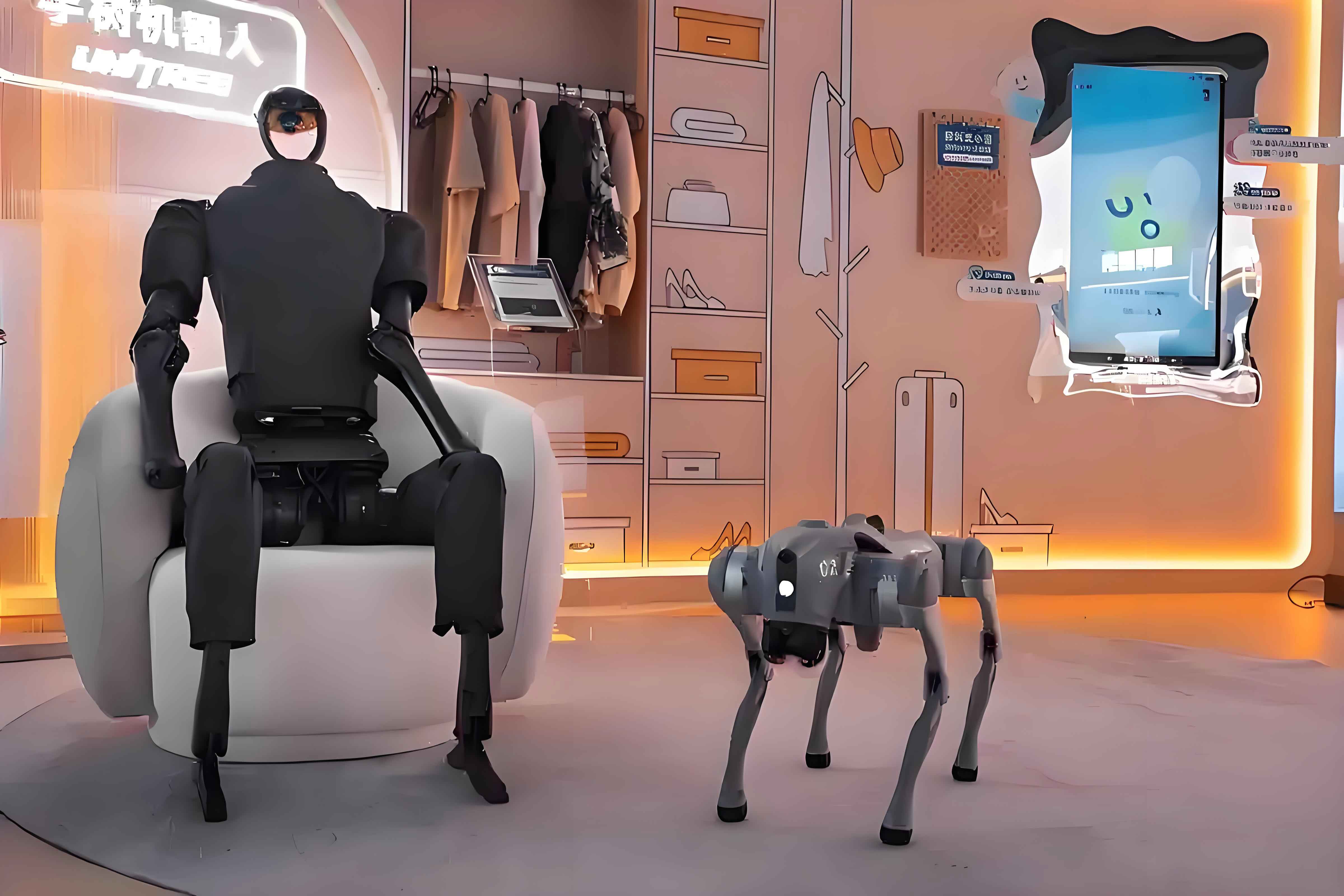
In recent years, many famous humanoid robots have been developed around the world. In Japan, Honda developed the P-series and later the ASIMO humanoid robot, which achieved dynamic walking, stair climbing, and autonomous operation. Sony and Fujitsu also developed small humanoid robots for entertainment and research. The University of Tokyo developed humanoids with toe joints to improve walking speed. In the United States, MIT built a robot capable of safe physical interaction with humans, while Yale University developed a robot that could recognize itself in a mirror. In China, the National University of Defense Technology built the “Pioneer” humanoid robot, and later Beijing Institute of Technology developed the “BHR” humanoid robot with many degrees of freedom and human-like motion capabilities. Most of these robots still use serial-chain legs. Thus, there remains a need to explore new hybrid configurations that are more anthropomorphic and more efficient.
The main contributions of this thesis are as follows. First, I analyze the human lower-limb joint structures and characteristics. Second, I propose a hybrid serial–parallel lower-limb mechanism for a humanoid robot. Third, I design the mechanical structure, including tendon-driven parallel ankle joints and a bridge-type hip joint. Fourth, I establish mathematical models for gait planning and perform kinematic analysis. Fifth, I create a three-dimensional virtual prototype and carry out dynamic simulations. Finally, I conduct physical experiments with a prototype to verify the theoretical results. The work provides a new structural concept and a theoretical basis for future humanoid-robot design.
2. Human Joint Characteristics and Gait Planning
To design a humanoid robot with anthropomorphic morphology and function, it is necessary to study the structure and movement of the human body. The proportions of the human body are usually expressed in units of head length. In traditional Chinese art theory, an upright human figure has about seven to seven and a half head-heights. Table 1 lists typical body dimensions of Chinese adults. These data provide a reference for determining link lengths and joint ranges of a humanoid robot.
| Measurement item | Male 18–60 | Female 18–55 |
|---|---|---|
| Body height (mm) | 1688 | 1586 |
| Eye height (mm) | 1574 | 1474 |
| Upper arm length (mm) | 313 | 284 |
| Forearm length (mm) | 237 | 213 |
| Thigh length (mm) | 465 | 438 |
| Lower leg length (mm) | 369 | 344 |
| Shoulder width (mm) | 375 | 351 |
| Foot width (mm) | 88 | 81 |
| Head length (mm) | 154 | 149 |
2.1 Human lower-limb joints
The human lower limb consists of the hip joint, knee joint, ankle joint, and foot joints. The hip joint is a ball-and-socket joint formed by the pelvis and the femoral head. It allows flexion, extension, abduction, adduction, and rotation. The knee joint is a trochlear joint that mainly permits flexion and extension around the frontal axis. The ankle joint is a saddle-like joint between the tibia, fibula, and talus; it permits plantar flexion, dorsiflexion, and a certain amount of inversion and eversion. The foot joints allow movement of the toes. The muscles and tendons around these joints act as actuators. When a muscle contracts, it pulls a tendon, which rotates the bone around the joint axis. This tendon-driven mechanism can be imitated by parallel mechanisms with linear actuators.
Table 2 summarizes the motion ranges and structural types of the main human lower-limb joints. It is important to notice that the hip and ankle joints have coupled multiple degrees of freedom, while the knee and toe joints can be approximated as single revolute joints.
| Joint | Range of motion (deg) | Joint type |
|---|---|---|
| Hip flexion/extension | −120 to 65 | Parallel ball-socket |
| Hip abduction/adduction | −30 to 40 | Parallel ball-socket |
| Hip internal/external rotation | −30 to 40 | Serial |
| Knee flexion/extension | 0 to 130 | Serial |
| Ankle plantar/dorsal flexion | −20 to 30 | Parallel |
| Ankle inversion/eversion | −15 to 15 | Parallel |
| Toe flexion/extension | −20 to 30 | Serial |
From the viewpoint of mechanism design, the human lower limb is not a pure serial chain. The hip and ankle joints are driven by multiple muscle groups arranged in parallel around the joint, and the joint motion is the result of coordinated shortening and lengthening of these muscles. Therefore, a hybrid serial–parallel mechanism is more anthropomorphic and offers better mechanical performance than a purely serial mechanism. In this work, I adopt this bio-inspired idea for the humanoid robot lower limbs.
2.2 Gait planning methods
Gait planning is the process of generating desired joint trajectories that enable a humanoid robot to walk stably. Several approaches exist.
Experimental measurement method. Human walking can be recorded by high-speed cameras and motion-capture markers. Then the recorded joint trajectories are transformed and scaled to the robot’s link lengths. This method gives natural-looking gait patterns but requires careful adaptation to the robot’s dynamic limitations.
Center-of-mass (COM) based planning. In this method, the gait is planned so that the ground projection of the COM always lies inside the support polygon. This static stability criterion works for slow walking but is too conservative for fast dynamic walking. The overall COM of the robot can be computed as
\[
x_G = \frac{\sum_{i} m_i x_i}{\sum_{i} m_i},\qquad
y_G = \frac{\sum_{i} m_i y_i}{\sum_{i} m_i}
\]
where \(m_i\) is the mass of the \(i\)-th link and \((x_i,y_i)\) are the coordinates of its mass center.
Zero-moment-point (ZMP) based planning. The ZMP is the point on the ground where the resultant moment of the gravity and inertia forces becomes zero. If the ZMP stays within the convex support polygon formed by the feet, the humanoid robot remains dynamically stable. The ZMP position can be computed as
\[
p_x = \frac{\sum_{i} m_i(\ddot{z}_i + g)x_i – \sum_{i} m_i \ddot{x}_i z_i}{\sum_{i} m_i(\ddot{z}_i + g)}
\]
where \(g\) is the gravitational acceleration, and \((x_i,y_i,z_i)\) are the coordinates of the mass center of link \(i\). The ZMP criterion is the most widely used stability criterion for dynamic biped walking.
Two-step planning method. In this thesis, I use a two-step planning method for the humanoid robot. The first step is to plan the trajectories of some joints according to the walking requirements. The second step is to solve the remaining joint motions using the dynamic balance condition, so that the whole system can move harmoniously. This method reduces the complexity of gait planning and is easy to implement in the actual control system.
The overall gait flow consists of three phases: starting phase, steady-walking phase, and stopping phase. During the starting phase, the robot first lowers its COM from the initial standstill height to a suitable walking height, then shifts the COM to the supporting foot, and finally moves one leg forward by half a step. During the steady-walking phase, the two feet alternately move forward while the COM transfers from one foot to the other. During the stopping phase, the reverse sequence is executed. The planned COM trajectory in the lateral direction follows a sinusoidal shape, and the height is kept almost constant during steady walking.
3. Structural Design of the Humanoid Robot
The mechanical structure is the foundation of the humanoid robot. A reasonable number and configuration of degrees of freedom (DOFs) are essential for walking, turning, stair climbing, and balance adjustment. In this thesis, each leg of the humanoid robot has seven DOFs: the hip has three DOFs (pitch, roll, and yaw), the knee has one DOF (pitch), the ankle has two DOFs (pitch and roll), and the toe has one DOF (pitch). Table 3 lists the DOF distribution of the whole lower limb.
| Leg section | DOF type | Number of DOFs | Remarks |
|---|---|---|---|
| Hip | Roll, pitch, yaw | 3 | Parallel + bridge-type |
| Knee | Pitch | 1 | Tendon-driven single joint |
| Ankle | Roll, pitch | 2 | Tendon-driven parallel |
| Toe | Pitch | 1 | Gear-driven |
| Per leg total | — | 7 | — |
| Two legs total | — | 14 | — |
3.1 Degrees-of-freedom analysis
The DOF configuration is determined by considering the required walking functions. During forward walking, the hip and ankle pitch joints coordinate with the knee joint to swing the legs. The hip roll joints and ankle roll joints coordinate to shift the COM laterally. The hip yaw joint enables turning. The toe joint improves walking speed, helps push-off, and provides impact absorption when the foot lands. Thus, a seven-DOF leg can realize both straight-walking and turning motions with sufficient flexibility.
3.2 Hybrid serial–parallel mechanism
Conventional humanoid robots usually use pure serial chains, where each joint is directly driven by a motor mounted at the joint axis. This leads to large joint torques, low stiffness, and heavy leg inertia. To overcome these disadvantages, I propose a hybrid serial–parallel configuration for the lower limbs. The main idea is to introduce parallel mechanisms at multi-DOF joints and to move the actuators proximally along the thigh and shank, similar to the way muscles act via tendons. The leg architecture can be described as two parallel clusters connected by serial single-DOF joints: the hip consists of a two-DOF parallel ball-socket mechanism connected in series with a yaw joint; the ankle is a two-DOF parallel ball-socket mechanism; the knee and toe are single revolute joints. This hybrid configuration reduces the load on the actuators, increases the stiffness and payload capacity, and makes the leg more anthropomorphic.
3.3 Tendon-driven ankle joint
The ankle joint of the humanoid robot is designed as a two-DOF spatial parallel mechanism, as shown schematically in my design. It consists of a fixed platform, a moving platform, and three connecting branches. Two branches are identical active branches composed of lead screws, guide rods, and ball joints; the third branch is a passive constraint branch built by a Hooke joint. The two active branches are driven by DC motors through lead screws. When the two motors rotate in the same direction, the ankle performs pitch motion. When they rotate in opposite directions, the ankle performs roll motion. Thus, the ankle can produce plantar flexion, dorsiflexion, inversion, and eversion within a certain range.
The tendon-driven parallel mechanism has several advantages. First, the motors and reducers are fixed on the lower leg, so the moving mass is small and the inertia of the foot is reduced. Second, the parallel arrangement can share the load, increasing the load capacity. Third, the linear actuators can provide a self-limiting effect by appropriately adjusting the guide-rod length, which prevents the joint from exceeding its allowable range. This makes the ankle joint more stable and reliable.
3.4 Bridge-type hip joint for turning
The hip joint has three DOFs. The roll and pitch DOFs are realized by a two-DOF parallel ball-socket mechanism similar to the ankle. The yaw DOF for turning is realized by a single-DOF mechanism. The yaw mechanisms of the left and right hips form a bridge-type serial connection. In this design, a DC motor drives a spur gear pair, which then drives a worm. The worm mates with a worm wheel, causing the support plate to rotate. The worm gear provides a high reduction ratio and self-locking ability, so the robot can maintain its posture even if power is suddenly lost. The bridge-type connection is compact and enables smooth turning motion.
3.5 Knee and toe joints
The knee joint is a single revolute joint driven by a single tendon-like mechanism. The motor rotates a short lead screw, which moves a nut block. The nut block is connected to a short guide rod, and the guide rod is connected by a link to the shank. When the motor rotates, the guide rod translates and pushes the link, causing the knee to flex or extend. This design is similar to the single-tendon parallel joint used in human knees.
The toe joint is added to improve the walking performance. It is driven by a gear pair. The toe joint allows the foot to push off the ground during the late stance phase, which increases the walking speed and improves the continuity of walking.
3.6 Actuator selection
DC servo motors are suitable for humanoid robots because of their small size, high efficiency, fast response, and good controllability. In this design, I select brushless or coreless DC motors with planetary gearheads. The selection process has three steps: preliminary calculation, theoretical verification, and simulation verification. I first estimate the required torque and speed for each joint using the planned trajectories and link masses. Then I choose the motor and gearbox. Finally, I check the selected motor in a three-dimensional dynamic simulation.
As an example, I calculate the torque required for the hip pitch joint. The leg is assumed to have a motion cycle of \(T = 1.0\,\mathrm{s}\), a step length of \(S = 0.2\,\mathrm{m}\), and a walking speed of \(0.2\,\mathrm{m/s}\). The angular acceleration of the swing leg during the acceleration phase is approximately \(\alpha = 2.5\,\mathrm{rad/s^2}\). The moment of inertia of the leg about the hip is about \(I = 0.35\,\mathrm{kg \cdot m^2}\). The required torque is then
\[
T_{req} = I \alpha = 0.35 \times 2.5 = 0.875\,\mathrm{N \cdot m}
\]
Considering the gearhead efficiency and a safety factor, the maximum required torque at the gearhead output is about \(1.4\,\mathrm{N\cdot m}\). Therefore, a motor with a stall torque above \(1.4\,\mathrm{N\cdot m}\) and a gearhead with a reduction ratio around \(64:1\) is selected. Table 5 lists the main parameters of the selected DC motors.
| Parameter | Value |
|---|---|
| Nominal voltage (V) | 24 |
| Nominal power (W) | 20–40 |
| Torque constant (mNm/A) | 10–20 |
| Speed constant (rpm/V) | 40–80 |
| Stall torque (mNm) | 100–300 |
| Max. continuous torque (mNm) | 20–60 |
| Max. efficiency (%) | 85–90 |
For the gearhead, multiple stages of planetary gears are used. Table 6 gives the typical gearhead parameters.
| Parameter | Value |
|---|---|
| Reduction ratio | 16:1, 64:1, 108:1 |
| Number of stages | 2–3 |
| Max. continuous torque (Nm) | 1.5–6 |
| Max. efficiency (%) | 80–90 |
The motors are connected to lead screws through couplings. The lead screw converts the rotational motion into translational motion of the nut block. The nut block is connected to the guide rod, which slides in linear bearings. The guide rod then drives the link and rotates the joint. This arrangement is compact and effective.
3.7 Sensor configuration
To realize stable walking, the humanoid robot needs to sense its actual ZMP and body posture. In this design, force sensors are placed on the soles of the feet to measure the ground reaction forces. The ZMP is then estimated from the force distribution. The sensors are strain-gauge type force sensors with a maximum capacity of \(200\,\mathrm{N}\), a resolution of \(0.5\,\mathrm{N}\), and an operating voltage of \(5\,\mathrm{V}\). Four sensors are mounted on each foot, two near the heel and two near the toe. By comparing the output values of the sensors, the controller can determine whether the ZMP is inside the support polygon. This information is used to adjust the joint angles in real time.
3.8 Overall design and prototype
After determining the DOF configuration, actuators, and sensors, I designed the mechanical parts with the aid of three-dimensional CAD software. The whole lower limb is assembled from components, including foot plates, shank plates, thigh plates, hip brackets, lead screw systems, ball joints, Hooke joints, gears, and worms. The final humanoid robot prototype has a height of about \(0.85\,\mathrm{m}\), a mass of about \(30\,\mathrm{kg}\), and fourteen DOFs in the lower limbs. The structure is compact and anthropomorphic. The designed lower limb can satisfy the requirements of straight walking, turning, and side-stepping.
4. Kinematic Analysis of the Humanoid Robot
4.1 Seven-link leg model
For gait planning and kinematic analysis, I simplify the humanoid robot as a spatial mechanism. Since the coupling between the forward motion and lateral motion is small, I analyze the model separately in the sagittal and frontal planes. The lower limbs are modeled as a seven-link open-chain mechanism. A coordinate system is fixed to the ground at the support foot. The model includes two feet, two shanks, two thighs, and an upper body, which is represented as one link. The joint angles are denoted by \(\theta_i\) for \(i=1,\dots,7\). The link lengths are denoted by \(L_i\). The mass of each link is denoted by \(m_i\), and the mass center location of each link is denoted by \((x_i,y_i)\).
4.2 Forward kinematics
Given the joint angles, the position of the mass center of each link can be computed. For a general planar multi-link system, the position of joint \(j\) relative to joint \(j-1\) is obtained by a rotation matrix. The position of the mass center of link \(i\) is expressed as
\[
\mathbf{p}_i = \mathbf{p}_{i-1} + \mathbf{R}(\theta_i) \mathbf{r}_{ci}
\]
where \(\mathbf{R}(\theta_i)\) is the planar rotation matrix, and \(\mathbf{r}_{ci}\) is the local vector from joint \(i-1\) to the mass center of link \(i\). Therefore, the forward kinematic equations can be written as the following set of coordinates:
\[
x_1 = l_{c1} \cos\theta_1,\qquad y_1 = l_{c1} \sin\theta_1
\]
\[
x_2 = l_1\cos\theta_1 + l_{c2}\cos\theta_2,\qquad
y_2 = l_1\sin\theta_1 + l_{c2}\sin\theta_2
\]
\[
x_3 = l_1\cos\theta_1 + l_2\cos\theta_2 + l_{c3}\cos\theta_3,
\]
\[
y_3 = l_1\sin\theta_1 + l_2\sin\theta_2 + l_{c3}\sin\theta_3
\]
\[
x_4 = l_1\cos\theta_1 + l_2\cos\theta_2 + l_3\cos\theta_3 + l_{c4}\cos\theta_4,
\]
\[
y_4 = l_1\sin\theta_1 + l_2\sin\theta_2 + l_3\sin\theta_3 + l_{c4}\sin\theta_4
\]
Similar expressions are obtained for the right leg links. Differentiating the position equations with respect to time yields the velocity Jacobian. This enables the controller to compute the joint velocities required for a desired foot trajectory.
4.3 COM trajectory planning
To ensure stable walking, the ground projection of the COM must lie inside the supporting foot at every instant. I plan the COM trajectory using the two-step gait planning method. The ideal COM trajectory in the forward direction, \(x_G(t)\), and the lateral direction, \(y_G(t)\), are designed as smooth periodic functions. In the sagittal plane, a typical COM height trajectory is given by
\[
x_G(t) = \frac{v t}{2} + A \sin\left(\frac{2\pi t}{T}\right)
\]
\[
y_G(t) = H + \frac{B}{2} \left[1 – \cos\left(\frac{2\pi t}{T}\right)\right]
\]
where \(v\) is the average walking speed, \(T\) is the step period, \(H\) is the nominal COM height, and \(A\) and \(B\) are small amplitudes used to reduce the impact at foot landing. The parameters are selected as \(v = 0.2\,\mathrm{m/s}\), \(T = 1.0\,\mathrm{s}\), \(H = 0.52\,\mathrm{m}\), \(A = 0.02\,\mathrm{m}\), and \(B = 0.01\,\mathrm{m}\). The COM trajectory curves are smooth and continuous, which helps the humanoid robot to maintain balance.
For the lateral motion, the COM must shift from one foot to the other. The lateral trajectory is planned as
\[
z_G(t) =
\begin{cases}
\frac{D}{2} – \frac{D}{2}\cos\left(\frac{2\pi t}{T_{dual}}\right), & 0 \le t \le T_{double} \\[4pt]
0, & \text{otherwise}
\end{cases}
\]
where \(D\) is the lateral distance between the feet, and \(T_{double}\) is the double-support duration. During the single-support phase, the COM is kept approximately above the support foot. This simple strategy ensures static stability during slow walking and can be extended to dynamic stability by using ZMP feedback.
4.4 Tendon-driven joint kinematics
For the tendon-driven parallel joints, the relationship between the joint angles and the actuator motions must be derived. I use the ankle joint as an example. The ankle mechanism consists of two active prismatic branches and one passive Hooke joint. The moving platform rotates relative to the fixed platform by two angles, \(\alpha\) and \(\beta\). The active branch lengths \(q_1\) and \(q_2\) are the distances between the ball-joint centers on the two platforms. Given the joint angles \((\alpha,\beta)\), the branch lengths can be computed by the inverse position solution. The coordinate transformation matrix from the moving platform to the fixed platform is
\[
\mathbf{R}_{m}^{f} =
\begin{bmatrix}
\cos\alpha \cos\beta & -\cos\alpha \sin\beta & \sin\alpha \\
\sin\beta & \cos\beta & 0 \\
-\sin\alpha \cos\beta & \sin\alpha \sin\beta & \cos\alpha
\end{bmatrix}
\]
where \(\alpha\) is the pitch angle and \(\beta\) is the roll angle. Then the coordinates of the ball-joint centers on the moving platform, expressed in the fixed frame, are
\[
\mathbf{p}_{i} = \mathbf{R}_{m}^{f} \mathbf{a}_{i} + \mathbf{d}
\]
where \(\mathbf{a}_{i}\) is the local position vector of the \(i\)-th ball center in the moving frame, and \(\mathbf{d}\) is the distance vector between the centers of the two platforms. The branch length \(q_i\) is obtained from
\[
q_i^2 = \|\mathbf{p}_i – \mathbf{b}_i\|^2
\]
where \(\mathbf{b}_i\) is the position vector of the ball center on the fixed platform. Expanding this equation gives
\[
q_1^2 = A_1 \cos\alpha + B_1 \sin\alpha + C_1 + D_1 \cos\beta
\]
\[
q_2^2 = A_2 \cos\alpha + B_2 \sin\alpha + C_2 – D_2 \cos\beta
\]
where \(A_i, B_i, C_i, D_i\) are constants determined by the platform geometry. Thus, by measuring the motor positions and the lead-screw pitches, the joint angles can be calculated directly. The inverse solution is also useful for converting the desired joint-angle trajectory into the required lead-screw displacement trajectory. This is the core of the low-level joint control for the humanoid robot.
4.5 Gait trajectory generation
Combining the COM trajectory and the inverse kinematics of the legs, I generate the joint-angle trajectories for all the lower-limb joints. The support leg and the swing leg have different roles. The support leg supports the body and keeps the torso upright, while the swing leg moves from the rear to the front. The foot of the swing leg is kept parallel to the ground to avoid tripping. The toe lift height is set to \(0.02\,\mathrm{m}\). The foot trajectory in the sagittal plane is planned as a fifth-order polynomial to guarantee continuous position, velocity, and acceleration:
\[
x_f(t) = s\left[10\left(\frac{t}{T_s}\right)^3 – 15\left(\frac{t}{T_s}\right)^4 + 6\left(\frac{t}{T_s}\right)^5\right]
\]
\[
z_f(t) = h\left[16\left(\frac{t}{T_s}\right)^2 \left(1-\frac{t}{T_s}\right)^2\right]
\]
where \(s\) is the step length, \(h\) is the maximum step height, and \(T_s\) is the swing duration. This polynomial trajectory prevents discontinuities in acceleration, which reduces the impact forces during walking.
5. Three-Dimensional Modeling and Simulation
5.1 Virtual prototype modeling
I built a complete three-dimensional solid model of the humanoid robot lower limbs using a CAD system. The CAD system allows parametric modeling, assembly, and motion simulation. The assembly process is simplified by dividing the lower limbs into subassemblies: left foot, left shank, left thigh, right foot, right shank, right thigh, and waist. The subassemblies are connected by revolute joints, ball joints, and prismatic joints according to the designed mechanism. The lead screw and nut are modeled as a sliding pair. The worm and worm wheel are modeled as a gear pair. After the assembly, I applied the servo motor drivers to the joints and performed a kinematic simulation.
5.2 Simulation results
The simulation verifies that all lower-limb joints move without interference. The designed joint trajectories produce a smooth and continuous walking gait. I measured the COM position during the simulation. The results show that the COM trajectory in the forward direction is close to the planned trajectory. In the lateral direction, the COM shifts smoothly from one foot to the other. The vertical COM motion has only a small fluctuation within \(\pm 5\,\mathrm{mm}\), which is acceptable for dynamic balance.
| Direction | Planned range (mm) | Simulated range (mm) | Error (mm) |
|---|---|---|---|
| Forward x | 0–200 | 0–198 | −2 |
| Lateral y | −30 to 30 | −28 to 28 | ±2 |
| Vertical z | 515–525 | 512–528 | ±3 |
The simulation also gives the joint torque curves. The maximum ankle torque occurs during the single-support phase, and the maximum hip torque occurs when the swing leg is accelerated. These torque data confirm that the selected motors and gearboxes are adequate. The virtual prototype thus provides an efficient way to validate the mechanism design and the gait planning before building the physical prototype.
5.3 Physical prototype experiment
After the simulation verified the feasibility, I built a physical prototype of the humanoid robot. The prototype is powered by DC motors with lead screws and worm gears. A control system using an embedded controller and motor drivers is installed. The foot pressure sensors provide the ZMP information in real time. The controller executes the planned joint trajectories and uses a simple feedback rule to adjust the hip and ankle angles if the ZMP deviates from the desired position.
I performed walking experiments on a flat floor. The humanoid robot successfully walked at a speed of about \(0.2\,\mathrm{m/s}\). The measured ZMP trajectory stayed inside the support polygon during most of the gait cycle. The robot also demonstrated turning and side-stepping motions. The experimental results validate the correctness of the theoretical analysis and the effectiveness of the proposed hybrid mechanism. The tendon-driven parallel joints made the leg motion smoother and increased the stiffness of the leg. The prototype is less noisy and more stable than a comparable serial-chain design.
| Experiment item | Result |
|---|---|
| Walking speed (m/s) | 0.2 |
| Step length (m) | 0.2 |
| Step height (mm) | 20 |
| Max ZMP error in x (mm) | 12 |
| Max ZMP error in y (mm) | 8 |
| Turning angle (deg) | ±30 |
| Gait cycle (s) | 1.0 |
The experimental results show that the humanoid robot can maintain stability while walking with the planned gait. The small ZMP errors are caused by link flexibility, backlash in the gearboxes, and the lag of the feedback control. These errors are within the allowable range of the foot support polygon. The physical tests also reveal some limitations of the current prototype. For example, the foot pressure sensors need better calibration, and the mechanical backlash in the worm gear should be reduced. In future work, I plan to improve the control algorithm and add a gyroscope and accelerometer to the upper body to further enhance the dynamic stability of the humanoid robot.
6. Conclusion
In this thesis, I designed and tested a novel lower-limb mechanism for a humanoid robot. The main conclusions are summarized as follows.
First, I analyzed the structure and motion characteristics of human lower-limb joints. The hip and ankle joints are parallel-driven multi-DOF joints, whereas the knee and toe joints are approximately single-DOF revolute joints. This anatomical insight is the basis of my bionic design.
Second, I proposed a hybrid serial–parallel lower-limb configuration for the humanoid robot. The two-DOF ankle joint and the two-DOF hip joint are realized by tendon-driven parallel mechanisms, which move the actuators from the joint axes to the limb segments. The hip yaw joint is realized by a bridge-type worm gear mechanism, which provides a high reduction ratio and self-locking ability. The knee and toe joints complete the lower-leg system.
Third, I established a seven-link kinematic model and derived the forward kinematics and COM trajectory equations for the humanoid robot. The two-step gait planning method was used to generate smooth and stable joint trajectories. The inverse kinematics of the tendon-driven ankle joint was also formulated, which connects the joint angles with the lead-screw displacements.
Fourth, I built a three-dimensional virtual prototype and simulated the walking motion. The simulation results show that the planned gait is feasible and the COM trajectory remains within the stable support region. The simulation also provided joint torque data for motor and gearbox selection.
Finally, I constructed a physical prototype and carried out walking experiments. The humanoid robot achieved stable walking, turning, and side-stepping motions. The experiments confirm that the proposed hybrid mechanism has good stiffness, smooth motion, and high load capacity. This work provides a new structural concept for the future development of humanoid robots.
There are still several topics that deserve further research. The mechanical structure should be optimized to reduce mass and improve energy efficiency. The control algorithm should be upgraded from a simple ZMP feedback to a more advanced model-based dynamic controller. Additional sensors such as inertial measurement units and vision sensors can be integrated to improve the autonomous capability of the humanoid robot. The dynamic stability analysis should be extended to fast walking, running, and stair climbing. These improvements will bring the humanoid robot closer to the ultimate goal of human-like locomotion.