
1. Introduction
Throughout the long history of human civilization, nature has served as an inexhaustible source of inspiration for technological innovation. The field of bionics, first formally proposed by J.E. Steele in the 1960s, has fundamentally transformed the way we approach engineering design by encouraging us to learn from, rather than merely exploit, the natural world. Among the most compelling frontiers of bionic engineering is the development of humanoid robots — machines designed to mimic the morphology, locomotion, and cognitive capabilities of human beings. The humanoid robot is not merely a technical curiosity; it represents a comprehensive integration of mechanics, electronics, materials science, control theory, and artificial intelligence. Its development serves as a critical indicator of a nation’s scientific and technological strength, and it holds immense potential for applications ranging from domestic service and healthcare to hazardous environment exploration and military operations.
Research on humanoid robots began in earnest during the 1960s. Early prototypes, such as the WABOT series in Japan and various experimental platforms in the United States and Europe, laid the groundwork for the sophisticated machines we see today. The evolution of the humanoid robot has been marked by a series of landmark achievements. For instance, the PETMAN robot developed by Boston Dynamics in 2008 demonstrated remarkable balance and dynamic locomotion, while its successor, the ATLAS robot, showcased advanced obstacle avoidance and whole-body manipulation capabilities. In Japan, Honda’s P3 and subsequently the ASIMO robot represented a major leap forward in bipedal locomotion and human-robot interaction. Closer to home, China’s “Xianxingzhe” (Pioneer) robot, developed by the National University of Defense Technology in 1990, and the BHR series and “Huitong” robot developed by Beijing Institute of Technology, have made significant contributions to the field. These machines, however sophisticated, still face fundamental challenges in replicating the seamless, fluid, and adaptive movements of the human body.
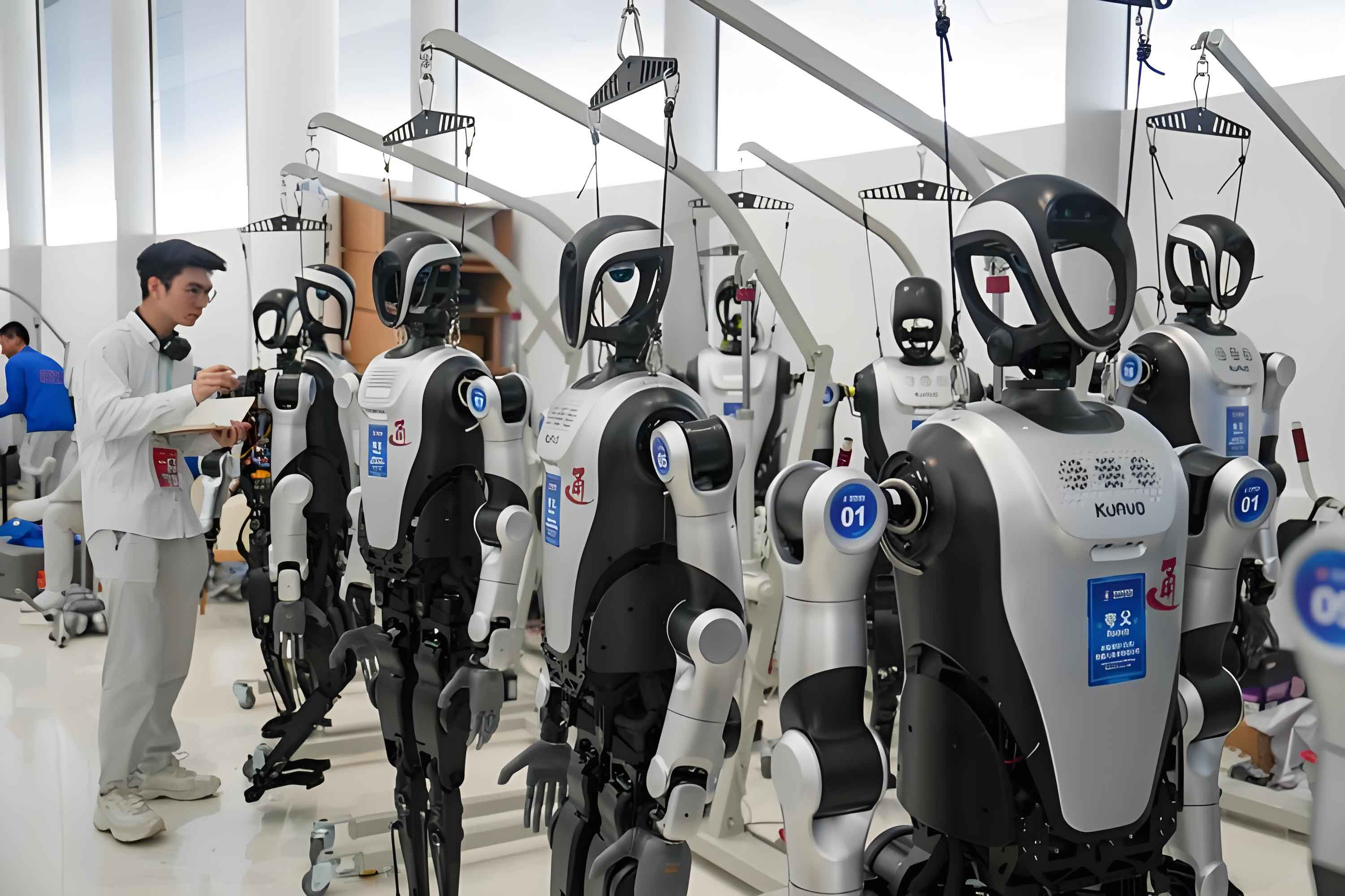
One of the most critical and challenging components in the design of a humanoid robot is the joint mechanism. The human body’s joints, particularly the shoulder, are marvels of biological engineering. They provide an extraordinary range of motion while maintaining structural stability and load-bearing capacity. Traditional robotic joints, however, have predominantly employed serial configurations — two or three single rotational pairs arranged in series, or combinations of double ball-and-socket joints. While these serial architectures are relatively straightforward to control due to their decoupled joint motions, they suffer from several inherent drawbacks. The actuators of distal joints become dead loads for proximal joints, reducing overall load capacity; the systems are often bulky, heavy, and exhibit limited stiffness; the motion is often decomposed into discrete, artificial-looking movements rather than the smooth, composite motions characteristic of human limbs; and the overall precision and dynamic performance are compromised. These limitations are particularly pronounced in critical joints such as the shoulder, hip, and spine.
From an anatomical perspective, the movement of human joints is accomplished through the coordinated action of multiple muscles through parallel drive mechanisms. This fundamental distinction between biological joints and conventional serial robotic joints suggests that parallel mechanisms may offer a more faithful and effective approach to joint bionics. Parallel kinematic mechanisms, characterized by multiple kinematic chains connecting a fixed base to a moving platform, offer superior stiffness, higher load capacity, lower inertia, and better precision compared to serial mechanisms. Among the various types of parallel mechanisms, spherical parallel mechanisms (SPMs) are particularly well-suited for joint applications because they provide pure rotational motion about a fixed point — exactly the kind of motion exhibited by ball-and-socket joints like the shoulder. This insight has motivated a growing body of research dedicated to exploring the potential of spherical parallel mechanisms for humanoid robot joint applications, especially for the shoulder complex.
Despite these advances, the application of parallel mechanisms to humanoid robot shoulders remains limited. Existing designs often fail to fully exploit the advantages of parallelism, and the relatively small workspace of parallel mechanisms remains a persistent obstacle. Moreover, the sizes and shapes of the workspaces of existing parallel joint mechanisms often do not align well with the actual range of motion of the human shoulder, which is a three-dimensional, coupled motion about multiple axes. Therefore, there is a pressing need for a systematic design methodology that can synthesize, analyze, and optimize spherical parallel mechanisms for shoulder bionics, with a particular emphasis on achieving a workspace that is not only large but also closely matches the functional workspace of the human shoulder. This thesis addresses this gap by presenting a comprehensive study on the bionic design of a humanoid robot shoulder joint based on a specific spherical parallel mechanism — the 3-PSS/S mechanism.
This work is supported by the Key Project of the Ministry of Education of China (No. 212012) and the Natural Science Foundation of Hebei Province (No. E2012203034). The overarching research objective is to establish a theoretical and practical framework for the design of biomimetic parallel shoulder joints, contributing to the broader advancement of humanoid robot technology. In the following chapters, I will systematically investigate the anatomical basis of the shoulder joint, perform a comparative analysis of various spherical parallel mechanisms, conduct a detailed kinematic analysis of a selected mechanism prototype, apply a genetic algorithm for structural parameter optimization, and finally present the design and preliminary prototyping of a bionic shoulder joint experimental model.
2. Structure and Function of the Human Shoulder Joint
2.1 Anatomical Composition
To design a truly biomimetic shoulder joint for a humanoid robot, it is essential to first develop a deep understanding of the human shoulder’s anatomy and its functional principles. The human shoulder — or more precisely, the shoulder complex — is a remarkably intricate structure. It is a multi-joint, multi-muscle system that connects the upper limb to the thorax, enabling a greater range of motion than any other joint in the human body. The shoulder complex comprises several bones: the scapula (shoulder blade), humerus (upper arm bone), and clavicle (collarbone). These bones articulate at four distinct joints: the sternoclavicular joint, the acromioclavicular joint, the scapulothoracic joint, and the glenohumeral joint. The glenohumeral joint, which is formed by the articulation of the head of the humerus with the shallow glenoid fossa of the scapula, is the primary ball-and-socket joint of the shoulder and is responsible for most of the arm’s rotational mobility.
A distinctive feature of the glenohumeral joint is the significant size mismatch between the large, spherical head of the humerus and the small, shallow glenoid cavity. This design prioritizes mobility over bony stability. To compensate for the shallow socket, the glenoid rim is surrounded by a fibrocartilaginous labrum, which deepens the socket by approximately 50% and enhances joint stability. The entire joint is encapsulated by a loose, thin articular capsule. While this capsule allows extensive movement, it also makes the joint more susceptible to dislocation, particularly in the inferior direction where there is minimal ligamentous and muscular reinforcement.
The stability and controlled mobility of the shoulder are achieved not by bony constraints but primarily by the coordinated action of the surrounding musculature. These muscles act as active, parallel tension elements — a perfect biological analogue to the actuators in a parallel robot. The key muscles of the shoulder include the deltoid, which abducts, flexes, and extends the arm; the rotator cuff muscles — the supraspinatus, infraspinatus, teres minor, and subscapularis — which provide dynamic stability and control rotational movements; the trapezius, which elevates and retracts the scapula; and the latissimus dorsi, pectoralis major, and teres major, which are prime movers for powerful adduction and internal rotation. The table below summarizes the primary muscles, their positions, and their functional roles in the humanoid robot shoulder bionics perspective.
| Muscle | Location | Primary Function |
|---|---|---|
| Trapezius | Superficial layer of the neck and upper back | Elevates, depresses, and retracts the scapula |
| Deltoid | Lateral aspect of the shoulder | Abducts the arm; anterior fibers aid flexion and internal rotation; posterior fibers aid extension and external rotation |
| Supraspinatus | Supraspinous fossa of the scapula | Initiates and assists shoulder abduction |
| Infraspinatus | Infraspinous fossa of the scapula | Externally rotates the humerus |
| Teres Minor | Inferior aspect of the infraspinatus | Externally rotates the humerus; adducts the arm |
| Teres Major | Inferior to the teres minor | Adducts and internally rotates the arm |
| Subscapularis | Costal surface of the scapula | Internally rotates the humerus; stabilizes the joint |
2.2 Motion Mechanism and Anatomical Planes
The motion of the shoulder joint is described with reference to three cardinal anatomical planes and three orthogonal axes. The anatomical planes are the sagittal plane, which divides the body into left and right halves; the frontal (coronal) plane, which divides the body into anterior and posterior sections; and the transverse (horizontal) plane, which divides the body into superior and inferior sections. The corresponding axes are the sagittal axis (anterior-posterior), the frontal (coronal) axis (medial-lateral), and the vertical (longitudinal) axis (superior-inferior). The following table defines these planes and axes:
| Type | Name | Definition |
|---|---|---|
| Anatomical Planes | Transverse plane | Horizontal plane dividing the body into upper and lower parts |
| Frontal (coronal) plane | Vertical plane dividing the body into anterior and posterior parts | |
| Sagittal plane | Vertical plane dividing the body into left and right parts | |
| Anatomical Axes | Sagittal axis | Anterior-posterior direction, perpendicular to the frontal plane |
| Frontal axis | Medial-lateral direction, perpendicular to the sagittal plane | |
| Vertical axis | Superior-inferior direction, perpendicular to the transverse plane |
From a kinesiological perspective, the human shoulder joint possesses six degrees of freedom (DoF) — three primary rotational DoFs and three secondary translational DoFs. The primary movements are flexion and extension (about the frontal axis), abduction and adduction (about the sagittal axis), and internal and external rotation (about the vertical axis). The normal ranges of motion for these movements are summarized in the following table. It is important to note that the overall range of motion of the arm is further augmented by the accessory motions of the scapula on the thoracic wall, known as scapulohumeral rhythm.
| Degree of Freedom | Axis | Motion | Normal Range |
|---|---|---|---|
| Rotational | Sagittal | Abduction | 0°–180° |
| Adduction | 0°–45° | ||
| Rotational | Frontal | Flexion | 0°–180° |
| Extension | 0°–60° | ||
| Rotational | Vertical | Internal rotation | 0°–75° |
| External rotation | 0°–90° |
This complex, large-range motion is the functional target for any biomimetic shoulder joint in a humanoid robot. The bionic design must be capable of generating motion whose workspace not only matches the size of the human shoulder’s workspace but also its three-dimensional shape and orientation.
3. Type Synthesis and Selection of Spherical Parallel Mechanisms for the Bionic Shoulder
3.1 Classification of Spherical Parallel Mechanisms
The selection of an appropriate mechanism is the most critical step in the design of a bionic joint for a humanoid robot. Given the ball-and-socket nature of the human shoulder, spherical parallel mechanisms (SPMs) are the natural candidates. SPMs are characterized by having three rotational degrees of freedom about a fixed point. Numerous SPM configurations have been developed over the years, each with its own kinematic architecture, advantages, and limitations. I have systematically classified and analyzed the most common SPMs that could potentially serve as a humanoid robot shoulder joint. The primary types are summarized in the following table.
| Mechanism Type | Architecture | Advantages | Disadvantages |
|---|---|---|---|
| 3-RRR | Three identical RRR kinematic chains, all axes intersecting at a common point | High stiffness; symmetrical structure; various derived architectures possible | Difficult to fabricate and assemble; nine revolute joints intersecting at one point; complex inverse kinematics |
| RRR-UPRR-RPUR | Hybrid chain with revolute, universal, prismatic, and revolute pairs | Three continuous rotational DoFs; multiple actuation choices | Complex chain with many joints; cumulative errors; motion not about fixed orthogonal axes, unlike human shoulder |
| 3-UPS/S | Three UPS chains with a central spherical joint for constraint | Good mechanical performance; suitable for heavy loads | Complex inverse kinematics; diminished operability for large tilts; smaller workspace |
| 3-PC(RR)N | Three PC (prismatic with circular guide) chains with two intersecting revolute joints each | Rotates freely about z-axis; compact with circular guides | Actuators not fixed to the base; moving mass is high; reduced dynamic performance |
| 3-PSS/S | Three PSS chains and a central spherical joint | Simple kinematics; easy to solve; high load capacity due to central strut; compact; large potential workspace | Workspace limited by central joint; central strut can constrain motion |
After careful consideration of the advantages and disadvantages of each mechanism, I identified the 3-PSS/S mechanism as the most promising candidate. This mechanism consists of a moving platform and a fixed base connected by three symmetrical PSS (prismatic-spherical-spherical) kinematic chains and a central spherical joint. The center of the central spherical joint coincides with the center of the moving platform and serves as the instantaneous center of rotation for the entire mechanism. The PSS chains do not constrain the motion of the moving platform, so the platform’s motion is governed solely by the central spherical joint, which allows three pure rotations. The reasons for this selection are manifold. First, its kinematic structure is simple and its inverse kinematics is computationally efficient, making it ideal for real-time trajectory planning and force control. Second, the inclusion of a central spherical joint significantly enhances the stiffness, stability, and load-bearing capacity of the mechanism. Third, the mechanism is highly symmetric, which simplifies analysis and design. Fourth, its workspace can be made quite large with appropriate dimensional synthesis and optimization.
3.2 Improved Prototype with Slope-Angled Actuators
To maximize the biomimetic potential of the 3-PSS/S mechanism, I have further refined its architecture based on the anatomical insights presented earlier. Drawing inspiration from two existing variants — one with co-planar second spherical pairs and another with inclined guide rails — I have proposed a new prototype configuration in which the three sliding actuators are arranged along the inclined guide rails whose axes converge at a common point on the vertical centerline of the mechanism. This arrangement offers several advantages. It allows for a more compact overall size, provides a larger driving stroke for the prismatic joints, and reduces the likelihood of interference among the branches. This new prototype is illustrated conceptually in the three-dimensional model of the 3-PSS/S spherical parallel bionic shoulder joint mechanism.
4. Kinematic Analysis of the 3-PSS/S Spherical Parallel Mechanism
4.1 Mechanism Description and Coordinate Systems
I consider the 3-PSS/S spherical parallel mechanism as shown in Figure 4-1, which consists of a moving platform defined by the equilateral triangle \(B_1B_2B_3\) with centroid \(B_0\), and a fixed base defined by the equilateral triangle \(C_1C_2C_3\) with centroid \(C_0\). The three identical PSS branches are connected between the base and the moving platform, and a central spherical joint S connects the centroids \(B_0\) and \(C_0\). The center of the central spherical joint, denoted as point O, is the instantaneous center of rotation in the mechanism. The prismatic joint of branch i (i = 1,2,3) moves a slider A_i along an inclined guide rail. The distance from the guide rail’s apex H to the slider A_i is \(d_i\). The connecting rod \(A_iB_i\) has a fixed length \(L_1\). The distance from the center of rotation O to the slider attachment point \(B_i\) on the moving platform is \(L_2\). The length of the vertical segment from the center of rotation O to the apex H is \(h\).
To describe the kinematics, I establish two coordinate frames. The first is the fixed (world) frame \(F: O-XYZ\), attached to the fixed base with its origin at the center of rotation O. The Z-axis is vertical and upward, and the Y-axis is parallel to \(C_2C_1\). The second is the moving frame \(M: o-xyz\), attached to the moving platform with its origin at the same point O. The z-axis is perpendicular to the moving platform and points upward, and the y-axis is parallel to \(B_2B_3\). Initially, when all actuator inputs are zero, the moving frame coincides with the fixed frame.
4.2 Inverse Kinematics Solution
The inverse kinematics problem involves determining the actuated joint variables — the distances \(d_i\) from the slider \(A_i\) to the apex H — for a given orientation of the moving platform. I use the RPY (roll-pitch-yaw) convention to represent the orientation of the moving platform with respect to the fixed frame. The rotation sequence is a yaw about the Z-axis by angle \(\gamma\), followed by pitch about the Y-axis by angle \(\beta\), and finally roll about the X-axis by angle \(\alpha\). The corresponding rotation matrix from the moving frame M to the fixed frame F is
$$
R_{M}^{F} = R_Z(\gamma) R_Y(\beta) R_X(\alpha)
$$
$$
=\begin{bmatrix}
c\gamma c\beta & c\gamma s\beta s\alpha – s\gamma c\alpha & c\gamma s\beta c\alpha + s\gamma s\alpha\\
s\gamma c\beta & s\gamma s\beta s\alpha + c\gamma c\alpha & s\gamma s\beta c\alpha – c\gamma s\alpha\\
-s\beta & c\beta s\alpha & c\beta c\alpha
\end{bmatrix}
$$
Here and in subsequent equations, \(s\) and \(c\) preceding an angle denote its sine and cosine, respectively. For example, \(s\alpha = \sin(\alpha)\) and \(c\beta = \cos(\beta)\).
The position vector of the slider A_i in the fixed frame is given by
$$
\mathbf{A}_i = \begin{bmatrix} d_i a_{xi} \\ d_i a_{yi} \\ d_i a_{zi} – h \end{bmatrix}
= \begin{bmatrix} d_i s\theta_i c\eta_i \\ -d_i s\theta_i s\eta_i \\ -d_i c\theta_i + h \end{bmatrix}, \quad (i=1,2,3)
$$
where \(\theta_i\) is the angle between the vertical line and the guide rail direction, and \(\eta_i\) is the angle between the projection of the guide rail direction in the OXY plane and the X-axis. For the specific symmetric arrangement under consideration, the three \(\eta_i\) angles are \(\eta_1 = -\frac{2\pi}{3}\), \(\eta_2 = \frac{2\pi}{3}\), and \(\eta_3 = 0\).
The position vector of point \(B_i\) on the moving platform, expressed in the fixed frame, is obtained by transforming its coordinates in the moving frame via the rotation matrix:
$$
\mathbf{B}_i^F = R_M^F \cdot {}^M \mathbf{B}_i
$$
Here, the coordinates of \(B_i\) in the moving frame are given by
$$
{}^M \mathbf{B}_i = \begin{bmatrix} L_2 s\theta’_2 c\eta’_i \\ -L_2 s\theta’_2 s\eta’_i \\ L_2 c\theta’_2 \end{bmatrix}
$$
In this bionic shoulder design, the second spherical pairs are coplanar with the moving platform, so \(\theta’_2 = 90^\circ\). The angles \(\eta’_i\) are \(\eta’_1 = \pi/3\), \(\eta’_2 = \pi/3\) and \(\eta’_3 = -\pi/3\) in the specific frame arrangement of the moving platform.
Since the connecting rod \(A_iB_i\) has a fixed length \(L_1\), I can write the constraint equation:
$$
| \mathbf{B}_i^F – \mathbf{A}_i | = L_1
$$
Squaring both sides and simplifying yields the inverse kinematics equation. After algebraic manipulation, this can be expressed in a quadratic form in terms of the actuated joint variable \(d_i\):
$$
U_i d_i^2 + 2(V_i – a_{zi} h) d_i + (W_i – 2 h g_{zi} + h^2) = 0
$$
where I have introduced the intermediate variables
$$
U_i = a_{xi}^2 + a_{yi}^2 + a_{zi}^2
$$
$$
V_i = -(a_{xi} g_{xi} + a_{yi} g_{yi} + a_{zi} g_{zi})
$$
$$
W_i = g_{xi}^2 + g_{yi}^2 + g_{zi}^2 – L_1^2
$$
The solution to the inverse kinematics is therefore
$$
d_i = \frac{-2(V_i – a_{zi} h) \pm \sqrt{4(V_i – a_{zi} h)^2 – 4 U_i (W_i – 2 h g_{zi} + h^2)}}{2 U_i}
$$
$$
d_i = \frac{-(V_i – a_{zi} h) \pm \sqrt{(V_i – a_{zi} h)^2 – U_i (W_i – 2 h g_{zi} + h^2)}}{U_i}, \quad (i=1,2,3)
$$
For a bionic shoulder joint in a humanoid robot, only the positive solution that is mechanically feasible is considered. This analytical solution is efficient and robust, making it suitable for real-time control.
4.3 Workspace Determination and Analysis
The workspace is one of the most critical performance indicators for a joint mechanism in a humanoid robot. Unlike conventional serial robots where the workspace is often a large volume in Cartesian space, the workspace of a spherical parallel mechanism is a set of orientations (attitudes) that the moving platform can reach. Since the reference point of the moving platform (its center) is fixed at the mechanism’s rotation center, the position workspace is trivial. Therefore, I define the workspace as the orientation workspace, which is the set of all RPY angles \((\alpha, \beta, \gamma)\) that satisfy the following constraints:
1. Actuator Stroke Limits: The actuator input \(d_i\) must lie within a physically feasible range. The rod \(A_iB_i\) must be able to connect the slider and the moving platform, so the triangle inequalities must be satisfied:
Additionally, the input \(d_i\) must lie within the range
$$|L_1 – L_0| \leq d_i \leq L_1 + L_0$$
$$L_0 = \sqrt{L_2^2 + h^2 – 2 L_2 h \cos \theta’_2}$$
2. Spherical Joint Angle Limits: The angular displacement of each spherical joint is limited. This condition is expressed as
$$
\theta_{min} \leq \theta_{ij} = \arccos\left( \frac{\mathbf{l}_i \cdot \mathbf{n}_{ij}}{|\mathbf{l}_i|} \right) \leq \theta_{max}
$$
where \(\mathbf{l}_i = \mathbf{B}_i^F – \mathbf{A}_i\) is the vector of the i-th connecting rod, and \(\mathbf{n}_{ij}\) represents the unit direction vector of the base of the j-th spherical joint in the i-th branch.
3. Link Interference: To prevent mechanical interference between adjacent connecting rods, the minimum distance between any two rods must exceed the rod diameter. Assuming the rods are cylinders of diameter D, this condition requires that
$$
D_i \geq D
$$
where \(D_i\) is the shortest distance between the centerlines of two adjacent rods. This is calculated by
$$
D_i = \frac{|(\mathbf{A}_m – \mathbf{A}_n) \cdot (\mathbf{l}_m \times \mathbf{l}_n)|}{|\mathbf{l}_m \times \mathbf{l}_n|}
$$
for the pairs (m,n) = (1,2), (2,3), and (3,1).
Based on the inverse kinematics solution and the constraint conditions, I developed a MATLAB program to search for all feasible orientation parameters \((\alpha, \beta, \gamma)\). The program follows a systematic procedure: it initializes the mechanism parameters, then for each orientation, it computes the actuator inputs and checks whether they satisfy all the constraints. If they do, the orientation is marked as part of the workspace. The resulting workspace is then plotted as a three-dimensional surface. As an illustrative example, a workspace plot is obtained by setting the fixed parameters to \(L_1=68\text{ mm}\), \(L_2=35\text{ mm}\), \(h=24\text{ mm}\), \(\theta_i=40^\circ\), and the maximum joint angles to \(\theta_{max}=40^\circ\). The search range for the RPY angles is from \(-90^\circ\) to \(90^\circ\) in increments that provide adequate resolution.
4.4 Influence of Structural Parameters on Workspace
To quantify the effect of each structural parameter on the orientation workspace, I have defined the workspace volume indicator S as the total number of reachable orientation points within the search space. A larger S value indicates a larger and more flexible workspace. Using a single-variable analysis approach, I varied one parameter while keeping all others fixed at their baseline values, and plotted S as a function of the varying parameter.
The influence of the rod length \(L_1\) on the workspace is shown in the following table and corresponding curve.
| Rod length L1 (mm) | Workspace Indicator S (points) |
|---|---|
| 52 | 0 |
| 56 | 0 |
| 60 | 520 |
| 64 | 4120 |
| 68 | 7356 |
| 72 | 6120 |
| 76 | 4010 |
| 80 | 1230 |
From this analysis, it is evident that the workspace initially increases sharply as \(L_1\) increases from 56 mm to 70 mm, reaching a maximum around 70 mm, and then decreases. There is an optimal rod length that maximizes the workspace.
The influence of the platform radius \(L_2\) on the workspace is summarized in the following table.
| Platform radius L2 (mm) | Workspace Indicator S (points) |
|---|---|
| 21 | 1200 |
| 25 | 3520 |
| 29 | 6240 |
| 33 | 7356 |
| 37 | 5230 |
| 41 | 2450 |
| 45 | 870 |
Similar non-monotonic behavior is observed for \(L_2\), with an optimal value around 33 mm. This indicates a trade-off between the lever arm length and the kinematic constraints.
The influence of the maximum joint angle \(\theta_{max}\) of the branch spherical joints is illustrated in the next table.
| Joint angle max (deg) | Workspace Indicator S (points) |
|---|---|
| 30 | 0 |
| 35 | 850 |
| 40 | 7356 |
| 45 | 11800 |
| 50 | 12900 |
| 55 | 13200 |
| 60 | 13200 |
| 65 | 13200 |
The workspace increases rapidly with the allowable joint angle up to approximately \(50^\circ\), after which the increase is negligible. This suggests that for angles greater than \(50^\circ\), the joint angle constraint is no longer a limiting factor; other constraints, such as link interference, become dominant.
Finally, the influence of the maximum joint angle of the central spherical joint \(θ_{4max}\) is given in the following table.
| Central joint angle max (deg) | Workspace Indicator S (points) |
|---|---|
| 10 | 250 |
| 15 | 2900 |
| 20 | 6100 |
| 25 | 7250 |
| 30 | 7356 |
| 35 | 7356 |
| 40 | 7356 |
These quantitative results are instrumental for the subsequent optimization of the mechanism’s structural parameters. They reveal that a high-performance bionic shoulder joint for a humanoid robot must be based on a careful trade-off among several competing factors.
5. Bionic Redesign of the 3-PSS/S Spherical Parallel Shoulder Joint
5.1 Design of a Novel Multi-ear Spherical Joint
A significant challenge in the design of the 3-PSS/S mechanism is the limited range of motion of the conventional central spherical joint. To overcome this constraint and enable the large rotational workspace required for a humanoid robot shoulder, I have designed a novel multi-ear spherical joint. This design is inspired by the anatomical structure of the human glenohumeral joint, where the shallow socket allows for extensive but stable movement.
The multi-ear spherical joint consists of three main components: a spherical head, a multi-ear base, and a base support. The multi-ear base is a cylindrical or conical structure that is split along its circumference to form a plurality of arc-shaped ears, each separated by a slot. The spherical head is attached to the moving platform via a shaft. In a conventional ball-and-socket joint, when the shaft tilts to the edge of the socket, it experiences hard interference. In the multi-ear design, however, the base is mounted on a bearing that allows it to rotate relative to the central column. When the spherical-head shaft contacts the upper edge of an ear, instead of stopping, it pushes the ear, causing the entire multi-ear base to rotate. The shaft then continues to move along the arc-shaped slot until it reaches the bottom or its motion is constrained by the actuator limits. This mechanism effectively increases the maximum allowable tilt angle of the central spherical joint.
During the experimental prototyping phase, I fabricated a multi-ear spherical joint specimen based on the engineering drawings. The measured maximum tilt angle of this new joint was approximately \(70^\circ\), compared to the conventional maximum tilt of about \(30^\circ\). This more than doubles the allowable deflection. This design is a key innovation that enables the 3-PSS/S mechanism to achieve a workspace large enough for shoulder bionics.
5.2 Offset Output Design
Even with the multi-ear spherical joint, the direct output of the 3-PSS/S mechanism may still not coincide in orientation and shape with the actual workspace center of the human shoulder. To address this issue, I have introduced the concept of offset output. The idea is to use an offset output shaft — a bent or tilted shaft attached to the center of the moving platform. The axis of this offset shaft does not coincide with the central axis of the moving platform. Instead, it is tilted by a constant angle \(t\), called the offset angle. As the moving platform rotates, the endpoint of the offset shaft traces a spatial path that is substantially different from that of the platform center. By choosing an appropriate offset angle and direction, one can redirect the output workspace to match the desired work volume of the human shoulder.
In my design, the offset shaft is placed in the \(o-yz’\) plane of the moving frame. The offset coordinate frame \(P: o’-x’y’z’\) is defined such that its \(z’\)-axis coincides with the offset shaft axis and points outward, its \(x’\)-axis coincides with the x-axis of the moving frame, and its \(y’\)-axis is determined by the right-hand rule. The transformation from the moving frame M to the offset frame P is a pure rotation about the x-axis by the offset angle \(t\):
$$
\mathbf{R}_P^M = \begin{bmatrix}
1 & 0 & 0 \\
0 & \cos t & \sin t \\
0 & -\sin t & \cos t
\end{bmatrix}
$$
The transformation from the offset frame P to the fixed frame F is therefore
$$
\mathbf{R}_P^F = \mathbf{R}_M^F \cdot \mathbf{R}_P^M
$$
By performing the matrix multiplication, I obtain the component form of \(\mathbf{R}_P^F\). This matrix describes the orientation of the offset output shaft with respect to the fixed base. The rotation matrix can also be expressed directly in terms of the RPY angles \(\alpha’\), \(\beta’\), \(\gamma’\) of the offset frame with respect to the fixed frame. By equating the corresponding elements of these two matrices, I have derived the mapping relationship between the orientation of the moving platform (the original mechanism output) and the orientation of the offset output shaft:
$$
\begin{cases}
\gamma’ = \gamma \\
\beta’ = \beta \\
\alpha’ = \alpha + t
\end{cases}
$$
This elegant result shows that the offset output design is mathematically equivalent to a constant offset in the roll angle. By carefully choosing the offset angle \(t\), the entire workspace of the mechanism can be effectively shifted in the roll direction by that amount.
5.3 Mapping to the Human Body Coordinate System
To ensure that the bionic shoulder joint can be integrated into a full humanoid robot, I have established a mapping between the mechanism’s coordinate system and the human body’s coordinate system. I define a world coordinate system \(W: O_W-X_WY_WZ_W\) fixed at the intersection of the anatomical planes. The X_W-axis points anteriorly, the Y_W-axis points to the left side, and the Z_W-axis points superiorly. I further define a shoulder coordinate system \(S: o_s-x_sy_sz_s\) with its origin at the acromion (the bony prominence on the shoulder), and its axes initially parallel to the corresponding axes of the world coordinate system. The orientation of the shoulder coordinate system relative to the world coordinate system is given by the RPY angles \((\alpha_s, \beta_s, \gamma_s)\).
The mechanism’s fixed frame F is attached to the upper torso of the humanoid robot, and its orientation relative to the world frame is given by the RPY angles \((\alpha_0, \beta_0, \gamma_0)\). The motion of the shoulder joint in the world coordinate system can be modeled as the motion of the offset frame P relative to the world frame. Since the shoulder joint motion is equivalent to the offset mechanism’s motion, I can write:
$$
\mathbf{R}_S^W = \mathbf{R}_F^W \cdot \mathbf{R}_P^F = \mathbf{R}_P^W
$$
Rearranging this equation, I obtain:
$$
\mathbf{R}_P^F = (\mathbf{R}_F^W)^{-1} \cdot \mathbf{R}_S^W
$$
Given the desired shoulder joint motion (i.e., the known values of \(\alpha_s\), \(\beta_s\), \(\gamma_s\), and the known mounting orientation \(\alpha_0\), \(\beta_0\), \(\gamma_0\)), the required orientation of the offset mechanism can be computed from the right-hand side of the above matrix equation. The resulting matrix elements are:
$$
\begin{aligned}
\mathbf{R}_P^F = \begin{bmatrix}
c\gamma’ c\beta’ & c\gamma’ s\beta’ s\alpha’ – s\gamma’ c\alpha’ & c\gamma’ s\beta’ c\alpha’ + s\gamma’ s\alpha’ \\
s\gamma’ c\beta’ & s\gamma’ s\beta’ s\alpha’ + c\gamma’ c\alpha’ & s\gamma’ s\beta’ c\alpha’ – c\gamma’ s\alpha’ \\
-s\beta’ & c\beta’ s\alpha’ & c\beta’ c\alpha’
\end{bmatrix}
\end{aligned}
$$
By equating this matrix to the product matrix from the right-hand side of the previous equation, I have derived the following closed-form expressions for the required offset mechanism orientation angles:
$$
\begin{cases}
\alpha’ = \arcsin\left(\frac{C}{\sqrt{1 – B^2}}\right) \\
\beta’ = \arcsin(-B) \\
\gamma’ = \arcsin\left(\frac{A}{\sqrt{1 – B^2}}\right)
\end{cases}
$$
where the auxiliary variables A, B, and C are defined as:
$$
A = s\gamma_s c\beta_s (c\gamma_0 s\beta_0 s\alpha_0 – s\gamma_0 c\alpha_0) – s\beta_s s\beta_0 c\alpha_0
$$
$$
B = s\gamma_s c\beta_s (c\gamma_0 s\beta_0 c\alpha_0 + s\gamma_0 s\alpha_0) – s\beta_s s\beta_0 s\alpha_0
$$
$$
C = c\gamma_s c\beta_s (c\gamma_0 s\beta_0 c\alpha_0 + s\gamma_0 s\alpha_0) + s\beta_s c\beta_0 s\alpha_0
$$
These formulas provide a systematic transformation between the desired shoulder joint motion of the humanoid robot and the required joint variables of the 3-PSS/S mechanism. It ensures that the bionic shoulder joint can be effectively controlled to produce motions that are coordinated with the overall body posture of the humanoid robot.
6. Optimization of the Bionic Shoulder Joint Based on Genetic Algorithm
6.1 Optimization Problem Formulation
After the kinematic and workspace analyses, I proceeded to optimize the structural parameters of the 3-PSS/S spherical parallel mechanism for the bionic shoulder joint. The primary objective is to maximize the orientation workspace indicator S, which represents the number of reachable orientation points within the specified search space. The structural parameters to be optimized are the connecting rod length \(L_1\), the moving platform radius \(L_2\), the maximum allowable joint angle of the central spherical joint \(\theta_{4max}\), the maximum allowable joint angle of the branch spherical joints \(\theta_{max}\), the distance \(h\) from the rotation center to the guide rail apex, and the guide rail inclination angle \(\theta_i\). I denote the vector of design variables as:
$$
\mathbf{x} = [x_1, x_2, x_3, x_4, x_5, x_6] = [L_1, L_2, \theta_{4max}, \theta_{max}, h, \theta_i]
$$
The design ranges were determined based on the workspace sensitivity analysis presented in Section 4.4 and the overall size constraints of a human shoulder:
| Parameter | Symbol | Range |
|---|---|---|
| Rod length | \(L_1\) | [58, 78] mm |
| Platform radius | \(L_2\) | [25, 45] mm |
| Central joint angle | \(\theta_{4max}\) | [35°, 55°] |
| Branch joint angle | \(\theta_{max}\) | [35°, 55°] |
| Guide rail apex distance | \(h\) | [14, 34] mm |
| Guide rail inclination angle | \(\theta_i\) | [30°, 50°] |
The optimization problem is to find the vector \(\mathbf{x}\) that maximizes the objective function \(S = f(\mathbf{x})\), subject to the kinematic and geometric constraints described in Section 4.3.
6.2 Genetic Algorithm Implementation
The genetic algorithm (GA) is a global optimization technique inspired by the principles of natural selection and genetics. It is well-suited for this type of multi-parameter, multi-constraint optimization problem. The GA iteratively evolves a population of candidate solutions using selection, crossover, and mutation operators until a termination criterion is met.
I implemented the GA in MATLAB. The key algorithmic steps are as follows:
Step 1: Initialization. The algorithm begins by generating an initial population of 200 individual chromosomes, where each chromosome represents a vector of the six structural parameters encoded as real numbers within their respective ranges.
Step 2: Fitness Evaluation. The fitness of each individual is computed by evaluating the objective function \(S = f(\mathbf{x})\), which is the number of reachable workspace points. Since the GA in MATLAB is designed to minimize a fitness function, I used a negative of the objective function, \(-S\), as the fitness value.
Step 3: Selection. Individuals are selected for reproduction based on their fitness. The selection probability is proportional to the fitness value, ensuring that higher-quality individuals have a higher chance of passing their genes to the next generation. I employed the normalized geometric selection method.
Step 4: Crossover. Crossover combines the genetic material of two parent individuals to generate offspring. For this real-coded GA, I used an arithmetic crossover operator. If two parents \(\mathbf{p}_1\) and \(\mathbf{p}_2\) are selected, the offspring are produced as follows:
$$
\mathbf{c}_1 = \mathbf{p}_1 \cdot a + \mathbf{p}_2 \cdot (1-a)
$$
$$
\mathbf{c}_2 = \mathbf{p}_1 \cdot (1-a) + \mathbf{p}_2 \cdot a
$$
where \(a\) is a random number uniformly distributed in the range (0, 1).
Step 5: Mutation. Mutation introduces random variations into the population to maintain genetic diversity and prevent premature convergence to a local optimum. I used a uniform mutation operator, which replaces a randomly selected gene with a new value drawn uniformly from its allowable range.
The GA was configured with a population size of 200, a maximum generation number of 100, and a mutation probability of 0.08. The convergence behavior of the GA is shown in the performance tracking graph. The graph depicts the average fitness of the population and the fitness of the best individual as functions of the generation number. As the GA progresses, the best fitness value increases monotonically, while the average fitness also shows a general upward trend. After about 60 generations, both curves flatten, indicating that the algorithm has converged to an optimum.
6.3 Optimization Results
The genetic algorithm converged to an optimal solution, which is summarized as follows:
$$
\mathbf{x}_{\text{opt}} = [L_1, L_2, \theta_{4max}, \theta_{max}, h, \theta_i] = [75.47 \text{ mm}, 31.88 \text{ mm}, 45.60^\circ, 55.00^\circ, 14.95 \text{ mm}, 38.21^\circ]
$$
The corresponding optimal value of the objective function is \(S_{\text{opt}} = 14719\). This value represents a substantial improvement over the workspace of the initial design. The following table compares the initial parameters and the optimized parameters:
| Parameter | Initial Value | Optimized Value |
|---|---|---|
| \(L_1\) (mm) | 68 | 75.47 |
| \(L_2\) (mm) | 35 | 31.88 |
| \(\theta_{4max}\) (°) | 45 | 45.60 |
| \(\theta_{max}\) (°) | 45 | 55.00 |
| \(h\) (mm) | 24 | 14.95 |
| \(\theta_i\) (°) | 40 | 38.21 |
The orientation workspace ranges before and after optimization are compared in the following table:
| Performance Metric | Before Optimization | After Optimization |
|---|---|---|
| Workspace indicator S | 7356 | 14719 |
| Range of α (°) | [-29.84, 30.32] | [-38.43, 38.92] |
| Range of β (°) | [-29.82, 24.59] | [-35.57, 36.05] |
| Range of γ (°) | [-90.00, 44.65] | [-90.00, 79.02] |
The workspace indicator S increased by 100.1%. The allowable ranges of the roll angle α and the pitch angle β each increased by more than 8°, while the allowable range of the yaw angle γ increased by approximately 34.5°. These results demonstrate the efficacy of the genetic algorithm in optimizing the workspace of the spherical parallel mechanism for a humanoid robot shoulder.
6.4 Verification of Optimization Results
To ensure that the GA did not converge to a local optimum, I performed a reverse verification procedure. In this procedure, the ranges of the structural parameters were narrowed around the optimal solution, and the objective function was modified to search for the minimum workspace instead of the maximum. If the optimal solution is truly a global optimum, the workspace in the minimized case should not be significantly different from the maximum. Using the same GA parameters but a negated objective function, the algorithm found a solution with a minimum workspace value of 13582 points. The difference between this value and the maximum value 14719 is 7.7%, which is relatively small. This indicates that the optimization landscape around the global optimum is relatively flat and that the GA has found a stable, near-global optimum.
7. Design and Fabrication of the Bionic Shoulder Experimental Prototype
7.1 Mechanical Design of the Prototype
The optimized structural parameters were used as the basis for the detailed mechanical design of the bionic shoulder joint experimental prototype. The overall design is composed of several key components: the central multi-ear spherical joint, the moving platform, the fixed base, and the three PSS branches.
Central Multi-ear Spherical Joint: The central joint is the core of the mechanism, providing the primary constraint while allowing rotational motion. The design of the multi-ear spherical joint was finalized based on the earlier prototype testing. The ball-and-socket interface is formed by a spherical head, which is fixed to the moving platform, and a multi-ear base. The multi-ear base is mounted on a rolling bearing that permits its rotation about the vertical axis. The arc-shaped slots in the multi-ear base are designed to accommodate the tilting of the spherical-head shaft. The physical prototype of the multi-ear spherical joint was successfully fabricated and tested. Its maximum tilt angle was measured to be approximately \(70^\circ\), which is more than twice that of a conventional spherical joint.
Moving Platform: The moving platform is designed to be a lightweight, high-stiffness component. Its geometry is an equilateral triangle with rounded corners. The outer edges form the platforms for the three secondary spherical joint bases, positioned symmetrically. The central area accommodates the mount for the spherical head of the central joint. The platform has been designed to ensure that all the spherical joint centers lie in the same plane.
Fixed Base and Guide Rails: The fixed base provides the structural ground for the mechanism. Three inclined guide rails are mounted symmetrically on the base. The inclination angle \(\theta_i\) of each guide rail with respect to the vertical direction is set to the optimized value of \(38.21^\circ\). The guide rails are designed to support the linear actuators. To reduce the overall system inertia and improve dynamic performance, the servo motors driving the prismatic joints are fixed on the base, not on the movable sliders. This design decision is critical for the dynamic control of the humanoid robot shoulder.
PSS Section Branches: Each branch is a PSS chain. To avoid the practical difficulties and large size of conventional spherical joints, I employed a hybrid joint configuration. The first spherical joint (adjacent to the prismatic actuator) is replaced by a combination of a U-joint and a revolute joint in series. The second spherical joint is replaced by a U-joint. This substitution maintains the zero-constraint property of the PSS branch while significantly increasing the allowable deflection angle and reducing the joint size.
To verify that this replacement does not alter the branch’s freedom, I used screw theory. The branch’s motion screw system is:
$$
\begin{aligned}
\$_{1} &= (0,0,0; & a, b, c) \\
\$_{2} &= (1,0,0; & 0,0,0) \\
\$_{3} &= (0,1,0; & 0,0,0) \\
\$_{4} &= (0,0,1; & 0,0,0) \\
\$_{5} &= (1,0,0; & 0,0,d) \\
\$_{6} &= (0,1,0; & 0,0,0)
\end{aligned}
$$
where \(a, b, c, d\) are non-zero real numbers. The reciprocal screw system of this set of twists is empty, which means that the branch does not impose any constraint on the moving platform, thus preserving the full rotational freedom. This validates the design alternative.
7.2 Three-Dimensional Virtual Prototype
Based on the optimized parameters and detailed component designs, I constructed a full three-dimensional virtual prototype of the bionic shoulder joint using the Pro/ENGINEER (Pro/E) software package. The virtual model integrates all the components: the fixed base with its three inclined guide rails and servo motors, the three PSS branches with their hybrid joint assemblies, the multi-ear central spherical joint, the moving platform, and the offset output shaft.
The final assembly is a compact, self-contained mechanism that replicates the three rotational degrees of freedom of the human shoulder. The offset shaft, which is fixed to the moving platform, provides the attachment point for the upper limb of the humanoid robot. The overall dimensions of the prototype are within the typical size range of a human adult shoulder, with a form factor that is compatible with integration into a full-body humanoid robot.
8. Conclusions and Future Work
In this thesis, I have presented a comprehensive study on the bionic design of a humanoid robot shoulder joint based on the 3-PSS/S spherical parallel mechanism. The key contributions and conclusions of this research are summarized as follows:
(1) I have systematically analyzed the anatomy and kinesiology of the human shoulder, establishing a functional specification for a biomimetic joint. The use of a spherical parallel mechanism was identified as a promising approach for achieving the necessary range of motion for a humanoid robot, inspired by the biological principle of parallel muscle actuation.
(2) I have compared various types of spherical parallel mechanisms and selected the 3-PSS/S mechanism as the most suitable candidate for a bionic shoulder joint. I further enhanced the architecture by incorporating inclined guide rails that converge toward an apex, which provides a more compact structure and reduces the potential for branch interference.
(3) I have performed a complete kinematic analysis of the 3-PSS/S mechanism, including an analytical solution to the inverse kinematics problem. I derived closed-form expressions for the actuator inputs as a function of the desired orientation of the moving platform. I also developed a numerical algorithm for computing the orientation workspace, taking into account actuator stroke limits, spherical joint angle limits, and branch interference constraints.
(4) I have quantitatively analyzed the influence of each structural parameter on the orientation workspace. The results reveal complex, non-monotonic relationships. This analysis laid the foundation for the subsequent optimization.
(5) I have proposed and fabricated a novel multi-ear spherical joint that significantly increases the allowable tilt angle of the central constraint joint. This innovation is critical to achieving the large workspace required for a shoulder joint. I also implemented an offset output design, which effectively shifts the mechanism’s output workspace to better align with the actual human shoulder workspace.
(6) I have applied a genetic algorithm to optimize the six key structural parameters of the 3-PSS/S mechanism, maximizing the workspace indicator. The optimized parameters increased the workspace by approximately 100% compared to the initial design. I further verified the global optimality of the solution using a reverse verification method.
(7) I have designed and fabricated a multi-ear spherical joint specimen and constructed a three-dimensional virtual prototype of the complete bionic shoulder joint, confirming the practical feasibility of the design. The successful fabrication and testing of the multi-ear joint validate its design principle and its potential for use in the final prototype.
While this research has made significant progress, there remain several important directions for future work:
Dynamic Modeling: The shoulder joint is subject to high dynamic loads during movement. A complete dynamic model of the 3-PSS/S mechanism should be developed to facilitate the design of high-performance controllers that can deliver fast, precise, and stable motions compatible with the dynamic characteristics of a humanoid robot.
Stiffness and Compliance Analysis: The elastic deformations of the components under load will affect the positioning accuracy and load-bearing capacity of the joint. A comprehensive stiffness analysis and structural optimization should be performed to maximize the load-to-weight ratio of the joint.
Intelligent Control: The mapping between the mechanism’s workspace and the human body’s motion space has been established. The next step is to develop intelligent control algorithms that can utilize this mapping to generate smooth, human-like motions for the humanoid robot.
Full Prototype Construction: Although the virtual prototype is complete, constructing a full functional physical prototype of the bionic shoulder joint is the ultimate validation step. This will involve the integration of servo motors, sensors, and a control system. Experimental evaluation of the mechanism’s workspace, accuracy, speed, and robustness will provide valuable feedback for further design refinements.
In conclusion, the work presented in this thesis establishes a solid theoretical and practical framework for the design of a novel bionic shoulder joint for a humanoid robot. The 3-PSS/S spherical parallel mechanism, enhanced with the multi-ear spherical joint and offset output shaft, demonstrates the potential to achieve the large, human-like workspace that is crucial for the next generation of advanced humanoid robots. This research contributes both to the field of mechanism theory and to the practical advancement of biomimetic robotics.