
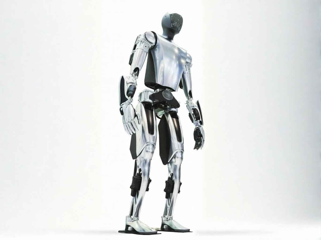
As a researcher deeply engaged in the field of robotics, my work has centered on a fundamental question: how do we create an embodied robot that can genuinely interact with the human world? The humanoid robot represents the ultimate expression of this quest—a machine that mirrors our physical form, our sensory capabilities, and ultimately, our behavioral patterns. In this research, I have focused on the head of an embodied robot, a critical component that houses the primary sensory organs and serves as the focal point for human-robot social interaction. The study of the head structure, auditory localization, and control system is not merely a mechanical exercise; it is an investigation into how an embodied robot can perceive, interpret, and respond to its environment in a manner akin to human behavior.
This thesis documents my comprehensive journey through the conceptualization, design, fabrication, and programming of a functional head for an embodied robot. The project, conducted under the auspices of a university 211 engineering initiative, has produced a physical, working system that demonstrates the principles of human-like motion, sound source localization, and precise motor control. The work is structured around three primary domains: the mechanical structure of the head, the auditory localization system, and the motion control architecture. Through this integrated approach, I have aimed to contribute to the broader field of embodied robotics by providing a platform that can be used to explore human-robot interaction, sensorimotor coordination, and the subtle nuances of non-verbal communication.
Introduction and State of the Art
Embodied robot research represents a convergence of computer science, control theory, mechanism design, information and sensing technology, artificial intelligence, and bionics. It is a field characterized by its high complexity and its integral role in advancing cutting-edge technology. The motivation behind building an embodied robot is twofold: to better understand ourselves through the act of recreation, and to develop machines capable of assisting humans in increasingly sophisticated and intuitive ways. Over the past few decades, the field has progressed from simple bipedal walkers to highly advanced, sensor-rich humanoids like Honda’s ASIMO and Sony’s QRIO, which can navigate dynamic environments, recognize faces, and respond to voice commands.
The head of an embodied robot is arguably its most crucial component. This is the area where the majority of human social cues are generated and received. The MIT Kismet robot, for example, features a head with 21 degrees of freedom (DOF) enabling a wide range of facial expressions, eye motion, and head poses. Similarly, the WABIAN-2R robot from Waseda University has a highly expressive head capable of conveying emotions like happiness, anger, and sadness through a combination of eyebrow, eyelid, and mouth movements. Internationally, there is a clear trend toward replicating the full spectrum of human facial and head movements to achieve natural and intuitive communication.
Within China, my home country, this field is also advancing rapidly. Significant progress has been made by institutions like Beijing Institute of Technology, which has developed an embodied robot with a functional visual tracking system. However, the research often focuses on singular aspects, such as vision or bipedal locomotion, without fully integrating the auditory, structural, and control mechanisms into a cohesive head unit. This presents a valuable opportunity to develop an integrated, multi-functional head for an embodied robot that addresses both the physical requirements of movement and the cognitive requirements of perception.
Mechanical Structure of the Embodied Robot Head
The primary goal of my head’s structural design was to achieve a balance between mimicking human motion, ensuring structural integrity, and maintaining a compact, lightweight form factor. After careful analysis of several mechanisms, I identified the need for a 4-DOF system: 3 DOF in the neck (yaw, pitch, and roll) and 1 DOF at the mandible to allow the jaw to open and close. This configuration is sufficient to replicate the essential head movements used in communication, such as nodding, shaking the head, tilting, and speaking.
Conceptual Design and Comparison
I evaluated several possible structural concepts to realize these degrees of freedom. The options ranged from configurations with staggered axes to those with intersecting axes, each presenting a unique set of trade-offs. Some designs placed significant cantilevered loads on the motors, demanding high-torque actuators that would increase weight and limit compactness. Others required complex mechanisms such as four-bar linkages or designs that could lead to cable entanglement during motion. After carefully weighing these factors, I concluded that a universal joint configuration would be the most advantageous. This approach, which I ultimately selected, simplifies the structure and provides robust support, as evidenced in Table 1.
Final Structure and Design Details
The final design divides the head’s pitching motion into two stages—a primary motion at the neck and a secondary motion at the upper cervical area—to more naturally distribute the angular displacement. The neck mechanism, built around a modified universal joint, handles the lateral and vertical tilt, while a vertical rotating motor at its base provides the yaw motion. The jaw is independently driven to open and close, completing the full set of four degrees of freedom. The resulting structure, fabricated primarily from aluminum alloy for its high strength-to-weight ratio, achieves a compact envelope of 140 cm × 180 cm × 380 cm, as detailed in Table 1. This design successfully maintained the total weight of the head, including the mounting plate, within the target range, which was crucial for selecting appropriately sized actuators.
| Item | Value |
|---|---|
| Primary Nod | -45° to +45° |
| Secondary Nod | -45° to +45° |
| Head Shake (Yaw) | -90° to +90° |
| Head Tilt (Roll) | -45° to +45° |
| Head Width | 140 mm |
| Head Depth | 180 mm |
| Head Height | 380 mm |
By using direct drive from the servo motors and eliminating reduction gears, I achieved several benefits. It simplifies the mechanical assembly, reduces the moment of inertia, and removes the non-linearity and backlash inherent in gear systems, leading to higher precision and a more responsive control system. The choice of the Maxon RE Ø25 motor, with a 128:1 planetary gearhead and 50-line encoder, provided the necessary torque and positional feedback for accurate motion. This mechanical platform, in essence, provided the physical “body” for the embodied robot, a vital component for its interaction with the world.
Auditory Localization System for the Embodied Robot
To enable the embodied robot to interact effectively with humans, I designed an auditory localization system inspired by the biological principle of binaural hearing. Humans determine the direction of a sound source by comparing cues between the two ears. The primary cues are the Interaural Time Difference (ITD) and the Interaural Level Difference (ILD). The ITD is the difference in arrival time of a sound wave at the left and right ears, while the ILD is the difference in the intensity or loudness of the sound at the two ears. For an embodied robot to localize sound, it must replicate these detection mechanisms.
Theory and Computation
My approach utilizes two microphones, placed to mimic the ears of a human. I approximated the head as a sphere with radius $a$ to formulate the time delay. If a sound source is positioned at an angle $\theta$ relative to the perpendicular axis of the head, the pathway difference for the sound to reach the far ear vs. the near ear can be expressed as $a \cdot \sin(\theta) + a \cdot \theta$. From this, the time difference $\Delta t$ can be calculated using the speed of sound in air, $c$:
$$ \Delta t = \frac{a(\sin \theta + \theta)}{c} $$
This can be simplified for small angles where $\sin(\theta) \approx \theta$, leading to a more practical formula based on the effective distance $h = 2a$ between the ears:
$$ \Delta t \approx \frac{2a \cdot \sin \theta}{c} $$
$$ \theta \approx \arcsin \left( \frac{c \cdot \Delta t}{2a} \right) $$
To compute this time delay from the digitized signals, I employed a mathematical process known as the cross-correlation function. This function measures the similarity of two signals as a function of a time lag applied to one of them. For the two audio streams, $x(n)$ and $y(n)$, the cross-correlation $r_{xy}(m)$ at a lag of $m$ is defined as:
$$ r_{xy}(m) = \sum_{n} x(n+m) y(n) $$
By finding the lag $m_i$ that maximizes $r_{xy}(m)$, I determine the time shift in terms of sample points. Dividing this sample shift by the sampling frequency $f_s$ yields the time delay $\Delta t$:
$$ \Delta t = \frac{m_i}{f_s} $$
Implementing this on the dual-channel audio input, I realized the entire processing chain—from signal acquisition to localization—in a real-time environment using Visual C++.
Implementation and Results
The hardware for the auditory system consists of two electret condenser microphones, each connected to a separate sound card installed in the computer. One sound card is the computer’s integrated audio device, while the other is a dedicated PCI sound card. This setup creates two independent audio input channels. The Sound component of the Microsoft DirectX API (DirectSound) was used to capture the audio streams from both microphones concurrently. This component provides low-level access to the sound hardware, allowing for efficient, low-latency audio capture into memory buffers.
One of the more subtle aspects of the implementation was buffering. I used a circular, streaming buffer, which allows for continuous capture and concurrent processing. The system was configured with a 22,050 Hz sampling rate, 8-bit resolution, and a single channel per microphone. This resolution was chosen to balance computational speed with adequate signal fidelity. Data from the buffer was read in frames of 16,384 bytes. To synchronize the processing with the buffer, I used position notifications that trigger an event when half of the buffer has been filled. These events were handled in a multithreaded environment to ensure that audio data from both channels was processed in real-time. Table 2 summarizes the key parameters of this system. The program flow, as illustrated in the original work, involves device enumeration, buffer declaration, and the execution of the main processing loop.
| Parameter | Specification |
|---|---|
| Microphone Type | Electret Condenser |
| Sound Hardware | Integrated + PCI Sound Card |
| Sampling Rate | 22,050 Hz |
| Sample Resolution | 8 bits |
| Frame Size | 16,384 Bytes |
| Buffer Size | 32,768 Bytes (2 Frames) |
The practical testing of the localization system yielded promising results. The visual interface, shown in the original work, provides a real-time representation of the signal waveforms and the computed direction of the sound source. While I achieved a functioning system, I observed that the accuracy could be improved. The precision is inherently limited by the sampling frequency and the dimensions of the head and can be adversely affected by environmental noise and reverberation, particularly for an embodied robot moving in the real world. The experiments validated the fundamental principles, showing that my embodied robot could successfully identify the quadrant and general direction of a sound source in a quiet environment.
Motion Control System of the Embodied Robot
The precision and fluidity of motion are what make an embodied robot appear lifelike, and this is heavily dependent on the control system. My approach centers on the use of a PMAC (Programmable Multi-Axis Controller) motion control card, which serves as the central brain for the motors. This system is a classic example of a closed-loop control architecture, which is essential for maintaining the accuracy and responsiveness required for the unique movements of the head.
Hardware Components
The core hardware for the control system is broken down into three main components:
1. Multi-Axis Controller: I chose a PMAC2A-PC/104 card from Delta Tau. This DSP-based controller is a powerhouse, capable of managing up to 8 axes of motion simultaneously. It executes sophisticated PID (Proportional-Integral-Derivative) control algorithms and provides a flexible interface for different types of motor drivers. The card opens a high-speed communication link with a host PC via a serial port, which allows for the development of custom user interfaces and control logic in a programming language like Visual C++.
2. Servo Motors: The choice of a servo motor over a stepper motor was a critical decision, primarily due to the closed-loop feedback nature of servo systems. This inherent difference provides control over torque, speed, and position, making them far more reliable for dynamic-torque applications. The direct-drive mechanism for the head necessitates a motor that can provide a substantial holding torque (approx. 2 N·m) at low speeds without overheating. My selection was a Maxon RE 25 DC motor, which, with its planetary gearhead (128:1), is well-suited for this task.
3. Servo Drives: To power and regulate the motors, I used a Copley Controls Accelnet MicroPanel amplifier (model ACJ-055-09). This digital drive is responsible for regulating the current and velocity loops, performing the high-frequency commutation and current control. It communicates with the PMAC card through a differential analog signal. A custom signal adapter box was necessary to convert the motor’s encoder output into a compatible differential signal for the amplifier. This amplifier was configured using Copley’s CME 2 software, which allowed for graphical tuning of the current and velocity control loops. The tuning process, as shown in Table 3, was critical for optimizing the motor’s performance.
| Control Loop | Tuning Method | Parameter | Value/Setting |
|---|---|---|---|
| Current Loop | Automatic + Manual | Proportional Gain | Optimized for stable response |
| Integral Gain | Minimized steady-state error | ||
| Velocity Loop | Manual (based on CME 2 Scope) | Proportional Gain | Reduced overshoot and settling time |
| Integral Gain | Eliminated steady-state velocity error |
System Integration and Debugging
The integration process begins with configuring the PMAC controller. A crucial initial step is setting the I-variables that define the communication and servo-loop frequencies. These values, such as the PWM frequency and the servo clock frequency, dictate the system’s bandwidth and are critical for stability. Getting the polarity correct was another key step. I tested the system by sending an open-loop command and verifying that the motor’s encoder count increased or decreased in the correct direction, as shown in the original debugging process. A mismatch here would cause a “run-away” condition, so it was crucial to get this right.
Once the communication and polarity were aligned, the next stage was tuning the PID gains within the PMAC. The standard process involved setting an initial proportional gain ($K_p=200$) and then introducing integral and derivative terms to compensate for steady-state errors and damping, respectively. The precise tuning process is detailed in Table 4. After the drive parameters were tuned, I performed a granular calibration to determine the number of encoder counts required for a 360-degree rotation of the motor output shaft, which was found to be 256,000 pulses. This figure is essential for the software to translate user-defined angles into precise motor commands.
| Variable | Description | Value |
|---|---|---|
| $I1900$ | PWM Frequency (Channels 1-4) | 1001 |
| $I1901$ | Phase Clock Frequency | 2 (12 kHz) |
| $I1902$ | Servo Clock Frequency | 3 (4 kHz) |
| $I110$ | Servo Interrupt Time | 17093 |
| $I169$ | DAC Output Limit | 1024 |
| $I130$ | Proportional Gain ($K_p$) | 200 |
| $I131$ | Derivative Gain ($K_d$) | Tuned by System Response |
The ultimate goal was to provide a user-friendly method for controlling these parameters. I leveraged the PtaTalk DT control (ActiveX), a communication tool for PMAC. By embedding this control in a Visual C++ (MFC) application, I could send commands from a visual interface to the PMAC. For instance, I created a button for a “single motor test” and a “four motor control” interface, as shown in the original work. The program calculates the required number of pulses from an input angle by using the pre-calibrated scale factor. This is achieved using the following logic in the code:
void CSingleMotorTestDlg::OnBnClickedTurn()
{
    UpdateData(TRUE);
    long tempJiaodu;
    CString str, str1;
    if (m_xishu == 0) { ... }
    else {
        tempJiaodu = (m_jiaodu * m_xishu) / 360;
        str1.Format("%d", tempJiaodu);
        str = "j:" + str1;
        m_PTalk.GetResponse(&response, "home");
        m_PTalk.GetResponse(&response, str);
    }
}
Ultimately, the control system proved to be stable, accurate, and responsive. The embodied robot head was successfully able to move to predetermined angles with the required speed and smoothness, affirming the validity of the PID tuning and the overall control software.
Conclusions and Future Work
In this research, I have successfully designed, fabricated, and integrated a functional head for an embodied robot. The primary achievements of this thesis can be summarized as follows:
1. Structural Innovation: I designed a novel and compact mechanical structure for the embodied robot head. The choice of a universal joint configuration proved to be a robust and effective solution for providing the required four degrees of freedom (3 DOF neck and 1 DOF jaw), enabling a wider range of motion that more closely mimics human behavior.
2. Integrated Auditory Perception: I implemented a real-time sound localization system based on binaural cues. The system uses cross-correlation analysis to compute the interaural time difference, proving that a low-cost, computationally feasible system can provide an embodied robot with a basic sense of auditory direction.
3. Reliable Control System: I established a complete control architecture based on a PMAC multi-axis controller and DC servo motors. Through painstaking tuning of the PID parameters within the PMAC and the drive amplifiers, I achieved stable and precise positioning. The custom Visual C++ interface made the system user-friendly and laid the groundwork for future complex motion sequences.
While this research has laid a solid foundation, it also opens up several directions for future investigation. The auditory localization accuracy remains a primary area for enhancement. I plan to improve the algorithm by incorporating HRTF (Head-Related Transfer Function) data, which will provide a more accurate spatial representation of sound. Additionally, using higher sampling rates and more sophisticated signal processing techniques like spectral filtering will aid in reducing the impact of noise and reverberation. Ultimately, I aim to integrate this audio processing with the visual system and the motor controls to create a reactive, embodied robot that can perform complex tracking sequences, such as turning to face a person who is speaking, in a natural and fluid manner. The precision of the motor axis rotation should also be verified using a more reliable external test method to further improve the position feedback accuracy.
In conclusion, this work represents a meaningful step forward in the development of an embodied robot with human-like perceptual and motor capabilities. The fully functional head, with its integrated structure, auditory perception, and control system, provides a valuable experimental platform. As I look toward the future, the journey from this foundational research to a truly autonomous, interactive embodied robot is both challenging and inspiring. The path forward is clear: continue to refine the perceptual algorithms, enhance the physical dexterity, and weave the systems together into an integrated being capable of understanding and participating in the complex world of human interaction.