
Humanoid robotics has long been a central focus within the robotics community, representing the pinnacle of mechatronic achievement by integrating mechanical engineering, electronic engineering, computer science, automatic control, artificial intelligence, and bionics. Since the 1960s, researchers worldwide have pursued the dream of creating machines that can walk, manipulate, and interact with the human environment. This thesis describes the systematic development of a miniature biped humanoid robot platform, named Robocean, and details the methodology used for its mechanical construction and the offline gait planning approach that enables stable walking. The overarching objective of this research is to establish a practical, cost-effective, and versatile platform that serves as a foundation for future explorations into autonomous and intelligent bipedal locomotion. In this context, the concept of the embodied robot becomes crucial, emphasizing that the physical body, its sensors, and its computational resources are deeply interconnected, and that intelligent behavior emerges from this physical embodiment.
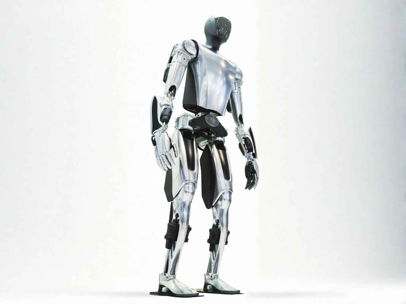
1. Introduction and Research Context
Compared with traditional wheeled or tracked robotic systems, the legged structure of a humanoid robot offers superior advantages. Humanoid robots can traverse uneven terrain, climb stairs, step over obstacles, and operate in environments designed for human beings. Their movement blind spots are significantly smaller, and their energy consumption is often lower than that of wheeled robots on irregular ground. More importantly, the bipedal walking mechanism, which is considered one of the most challenging forms of terrestrial locomotion in nature, provides an ideal experimental platform for studying complex, high-order, nonlinear, and non-holonomic dynamic systems. The development of humanoid robots also drives progress in many related disciplines, such as bionics, artificial intelligence, computer graphics, and sensor technology.
The international landscape of humanoid robotics is dominated by pioneering efforts, particularly in Japan. Honda’s P-2, introduced in 1996, was the first untethered autonomous humanoid robot, setting a global benchmark. Its successor, ASIMO, which debuted in 2002, demonstrated advanced dynamic walking using a combination of Zero Moment Point (ZMP) control and predictive motion control, enabling seamless transitions between walking, turning, and climbing stairs. Sony’s SDR-4X showcased a compact platform with extensive DOF and intelligent interaction capabilities. Research institutions like KAIST in Korea (KHR-1) and AIST in Japan (HRP-2) have also made significant contributions, focusing on efficient walking patterns and human-robot collaboration. In this international context, the development of an embodied robot that closely mimics human morphology is a continuous endeavor, aiming to achieve not only functional performance but also harmonious coexistence with humans.
In China, research started relatively later. Changsha National University of Defense Technology developed the “Pioneer” humanoid in 2000, a 1.4-meter-tall platform, followed by Beijing Institute of Technology’s BHR-2, which is considered the most advanced domestic system, capable of performing complex dynamic actions like Tai Chi. Despite this national progress, there was a noticeable gap in the field of small-scale, low-cost, yet functional humanoid robot platforms. These miniaturized platforms are essential for research laboratories and educational institutions, allowing for intensive studies on gait algorithms without the complexity and cost associated with human-scale robots. This gap served as the primary motivation for this thesis. The goal of this work is to design and construct a miniature biped humanoid robot named Robocean.
The key contributions of this thesis are twofold. First, it details the complete mechanical design process of a miniature robot, which serves as a fully functional embodied robot platform. This includes the configuration of its degrees of freedom (DOF), the selection of appropriate actuators, sensors, and controllers, and the design of its physical structure. Second, and perhaps more significantly, this thesis presents a novel “three-step planning method” for offline gait generation. This method systematically addresses the challenges of bipedal walking, including pose planning, kinematic model resolution, and trajectory correction, ultimately enabling the robot to achieve smooth and stable static walking.
2. Mechanical Structure Design of the Robocean Platform
The design of the open and modular Robocean platform is driven by several clear principles: the ability to achieve stable bipedal walking, smooth and aesthetically pleasing motion, miniaturization (height under 50cm), simplicity of structure to reduce weight, use of standard components to lower cost, and an attractive appearance conducive to human-robot interaction. The materials selected were aluminum alloy (LY12) for the load-bearing connector components and nylon (1010) for other structural parts. The entire design philosophy is centered on creating an embodied robot where every mechanical component and sensor contributes directly to the robot’s ability to perceive and interact with its environment in a stable and purposeful manner.
2.1 Degrees of Freedom Configuration
The first step in the mechanical design is the determination of the robot’s degrees of freedom. This requires a careful analysis of the human skeletal system, which is a complex, variable-structure system with over 200 degrees of freedom that are capable of producing highly coordinated motion. Since it is impossible and impractical to fully replicate this biological complexity in a mechatronic system, the main goal is to use as few degrees of freedom as possible to achieve as many basic movements as possible, while ensuring these movements are smooth and natural.
The lower limbs are the most critical components for walking. By studying the motion of human legs, I found that 12 DOF can approximately reproduce all the functional movements of a human leg: 6 DOF (2 x 3) for forward motion, 4 DOF (2 x 2) for lateral motion, and 2 DOF (2 x 1) for turning. To reduce weight and simplify the system, the two turning DOF were omitted. Thus, the lower limb configuration includes a total of 10 DOF, with 3 DOF at each hip (forward, lateral, and yaw rotation), 1 DOF at each knee (forward), and 1 DOF at each ankle (forward). The upper limbs function as the robot’s manipulators and also serve as essential tools for maintaining balance during walking. I allocated 6 DOF to the arms: 2 DOF at each shoulder (for forward and lateral motion) and 1 DOF at each elbow (for flexion). The head, which is intended for sensor integration, has 1 DOF for panning motion. In total, the Robocean platform has 17 DOF. This configuration is a compromise between mechanical complexity and required functionality.
| Body Segment | Number of DOF | Joint Distribution | Purpose |
|---|---|---|---|
| Lower Limbs | 10 | Hip (3 DOF each), Knee (1 DOF each), Ankle (1 DOF each) | Forward motion, lateral sway, posture support |
| Upper Limbs | 6 | Shoulder (2 DOF each), Elbow (1 DOF each) | Balance compensation, task execution |
| Head | 1 | Neck (1 DOF) | Sensor orientation, environmental perception |
| Total | 17 | – | Overall locomotion and interaction |
2.2 Actuator and Control System Selection
Selecting the correct actuator is crucial for the performance of the embodied robot. While some early research used pneumatic artificial muscles to replicate human muscle contraction, they did not become widely adopted due to their physical proportions and mechanical limitations. In modern robotics, DC servo motors are the standard choice due to their speed, torque, and built-in position feedback capabilities. For the Robocean, I selected the TowerPro-MG995 micro servo motor for its excellent torque-to-weight ratio, small size, and low cost.
The TowerPro-MG995 is a miniature servo motor with an internal closed-loop feedback system. It operates based on pulse-width modulation (PWM), where the width of the incoming pulse determines the angular position of the output arm. Key specifications are listed in the table below. In my design, I need to ensure that the motor’s torque is sufficient for the robotic structure. The maximum torque of the MG995 is 15 kg/cm. Therefore, the total mass of the robot must be kept below 2.15 kg to ensure reliable and robust driving of the joints.
| Specification | Value |
|---|---|
| Dimensions | 40.6mm x 19.8mm x 37.8mm |
| Weight | 55.2 g |
| Operating Voltage | 4.8V – 7.2V |
| No-load Speed | 0.24 sec/60 degree (6.0V), 0.2 sec/60 degree (7.2V) |
| Stall Torque | 13.0 kg/cm (6.0V), 15.0 kg/cm (7.2V) |
| Gear Train | Metal gears, double ball bearings, three-stage rotor |
For the control system, I selected a self-developed multi-channel motion control board. This board, which is based on a centralized control architecture, can be placed on the robot’s back and can independently control up to 32 micro servo motors simultaneously. This centralized control approach simplifies communication and allows for the coordination of a complex sequence of movements, which is essential for bipedal locomotion. The board receives serial commands from a PC or other control system via a communication cable, and its small size and light weight allow it to be integrated into the robot platform, enabling untethered operation.
2.3 Sensor Integration
To achieve stable walking and enable future intelligent interactions, a robust sensory system is essential. The embodied robot relies on sensory feedback to adapt to its environment and maintain balance. For the Robocean, I implemented a strategy of “offline planning with online adjustment.” In this approach, the gait is initially planned offline, and then fine-tuned in real-time based on sensor data. This requires measuring the actual ZMP (Zero Moment Point) to compensate for the difference between the expected and the actual ZMP.
Three common methods are used to measure ZMP: 1) calculating the ZMP from the velocities and accelerations of all robot components, 2) using pressure sensors on the soles of the feet to calculate the ZMP, and 3) using six-axis force/torque sensors at the ankles. The second method, involving pressure sensors on the soles, is particularly well-suited for small robots due to its simplicity and cost-effectiveness. I chose to use four LK series pressure sensors placed on the sole of each foot. As the robot walks, these sensors measure the ground reaction forces, which are then used to calculate the actual ZMP position. The calculation is as follows:
$$X_{ZMP} = \frac{\sum_{n=1}^{4} X_n \cdot Fz_n}{\sum_{n=1}^{4} Fz_n}, \quad Y_{ZMP} = \frac{\sum_{n=1}^{4} Y_n \cdot Fz_n}{\sum_{n=1}^{4} Fz_n} \tag{2-1}$$
where \(X_n\) and \(Y_n\) are the coordinates of the \(n\)-th sensor, and \(Fz_n\) is the vertical force measured by the \(n\)-th sensor. This data is critical for feedback control, enabling a real embodied robot to maintain its balance based on physical interaction with the ground. The head is additionally equipped with a vision sensor, a microphone, and a speaker to provide and enhance human-robot interaction capabilities, capturing images and sound from the environment.
3. Gait Planning Methodology
Gait planning is the process of generating the desired joint trajectories that allow the robot to walk. The primary objective is to ensure stable locomotion. The challenge lies in the high dimensionality and non-linear dynamics of the bipedal robot. In this thesis, I adopt the “Off-line planning, On-line adjustment” strategy, focusing primarily on the offline portion. Traditional methods often treat the forward and lateral motion separately, creating mechanical and unnatural gaits. The “two-step planning method” often involves the robot first performing a full lateral sway to shift the center of gravity onto one foot, then raising the other foot and taking a step. While stable, this results in a rigid, jerky motion. Building on this foundation, I introduce a novel method termed the “three-step planning method”.
3.1 Foundational Concepts
The feasibility of a gait is determined by its adherence to two basic principles: 1), the planned gait must achieve the designated task (e.g., moving forward at a certain speed); and 2), the gait must ensure the robot’s stability. I adopt the “parallel gait” and “static walking” strategy for Robocean. Static walking implies that the projected center of gravity (COG) remains within the support polygon at all times. The COG is calculated as:
$$X_{cg} = \frac{\sum_{i=1}^{n} m_i g X_i}{\sum_{i=1}^{n} m_i g}, \quad Y_{cg} = \frac{\sum_{i=1}^{n} m_i g Y_i}{\sum_{i=1}^{n} m_i g} \tag{3-1}$$
where \(m_i\) is the mass of the \(i\)-th link, and \(X_i\) and \(Y_i\) are its coordinates. This approach is applicable when the robot moves at a low speed, and the inertial forces are negligible, making the ZMP criterion equivalent to the COG criterion. The parallel gait refers to a walking style where the footprints of the two feet form two parallel lines. This mode is chosen over the “one-line” (straight) gait because it requires fewer DOF while providing a larger stability margin.
3.2 The Three-Step Planning Method
To address the limitations of the two-step planning method, where forward motion and lateral sway are strictly sequential, I introduced the three-step planning method. This method allows for a more fluid and natural gait. It is based on the principles of human walking where the body continuously adjusts its balance while moving forward. The three steps are:
- Step 1: Pose and Trajectory Planning. Based on the desired gait parameters (e.g., step length, step period), the robot’s walking posture and the trajectory of its center of mass are programmed. For a natural appearance and stability, the robot’s torso remains perpendicular to the ground, and its hip height is kept constant.
- Step 2: Kinematic Model Resolution and Motion Curve Generation. Kinematic equations are established for the robot. By providing the trajectories from Step 1 into these equations, the angular motion curves for every joint are calculated. These joint trajectories ensure that the kinematic constraints are satisfied.
- Step 3: Trajectory Correction. Due to the coupling between lateral and forward movements, the actual ZMP trajectory may deviate from the planned one. This step seeks to correct the motion curves to reconcile these movements, ensuring the robot maintains stability while achieving a more fluid walking motion.
The complete walking process is divided into three phases: the starting phase, the normal walking phase, and the stopping phase. During the starting phase, the robot lowers its center of mass and executes a half-step to transition from a static state to the walking state. The normal walking phase consists of a periodic alternating step motion. The stopping phase is the inverse of the starting phase, where the robot raises its center of mass and returns to a standstill position.
3.3 Human Motion Capture Data (HMCD) Analysis
To generate a bio-inspired and optimal gait, I performed an analysis of human gait data. This data, derived from high-speed camera recordings of human subjects, reveals fundamental walking principles. The data shows that humans walk with the torso almost vertical and the ZMP tracing a sinusoidal curve between the feet. The hip trajectory shows minimal vertical oscillation. The entire process can be modeled to achieve not only stability but also energy efficiency. In an embodied robot, applying these human-derived principles can lead to more efficient and natural locomotion. The single support phase and double support phase alternate to ensure a smooth transfer of body weight. I incorporate these observations into the Step 1 of the planning process, aiming to avoid complex dynamic calculations and obtain a kinematically optimized gait.
4. Detailed Gait Planning for Robocean
Following the three-step planning method, the first step is to define the robot’s desired walking posture and body trajectories. I define the walking speed to be 60 mm/s, with a stride length of 120mm. The robot’s initial center of gravity height is 277.5mm, which is lowered to 252.5mm during the normal walking phase to increase stability. The foot lifting height is set to 15mm, allowing for adequate ground clearance while minimizing energy expenditure. The planned center of gravity trajectory is defined as a sinusoidal curve in the lateral direction, and the foot trajectory in the vertical direction is also defined as a sinusoidal curve, ensuring zero vertical velocity at the moment of ground contact to minimize impact.
4.1 Kinematic Modeling and Equation Solving
The next step requires establishing a kinematic model. The legs are modeled as two separate serial-chain mechanisms. A homogeneous transformation matrix is established for each leg. For the right leg, the reference coordinate system is at the foot, and for the left leg, the reference is at the hip. The transformation matrix for the right leg is \(^0_6T\), which is a function of the 5 joint angles \(\theta_1\) to \(\theta_5\), plus the static dimensions. The pose constraints for the torso and ankle, i.e., staying upright and parallel to the ground, give us the following simplification:
$$^0_6T = \begin{bmatrix} 1 & 0 & 0 & P_x \\ 0 & 1 & 0 & P_y \\ 0 & 0 & 1 & P_z \\ 0 & 0 & 0 & 1 \end{bmatrix} \tag{4-2}$$
where \(P_x\), \(P_y\), \(P_z\) are the coordinates of the center of mass relative to the right foot. The kinematic analysis yields the relationship between joint angles: \(\theta_2 + \theta_3 + \theta_4 = 0\) and \(\theta_1 + \theta_5 = 0\). This simplification greatly reduces the complexity of the equations. Similarly, for the left leg, we obtain the transformation \(^6_{12}T\), and its own constraint equations, \(\theta_7 + \theta_8 + \theta_9 = 0\) and \(\theta_6 + \theta_{10} = 0\).
Solving these equations requires input from the trajectory planning step. In the starting phase, the equations are:
$$ \begin{cases} P_y = 0, & P_z = 277.5 – 15t, & t \in (0, 1s) \\ P_y = 30t, & P_z = 252.5, & t \in (1, 2s) \end{cases} \tag{4-11}$$
These equations are then applied to the transformation matrix \(^0_6T\) to solve for the joint angles \(\theta_2\) and \(\theta_3\). Similarly, for the left leg in the normal walking phase, the trajectory equations are:
$$ \begin{cases} P_y = 0, & P_z = -252.5 + 15 \sin(2\pi t), & t \in (2, 3s) \\ \end{cases} \tag{4-16}$$
By solving these equations, I obtain the motion curves for the knee and hip joints. Due to the symmetry of walking, the motion curve of the right leg in the first half of the cycle is identical to the motion curve of the left leg in the second half. This approach dramatically simplifies the calculation. The resulting joint motion curves define the required angles for all the joints over time. These are the target trajectories for the embodied robot.
4.2 Trajectory Correction and Error Analysis
Solving the kinematic equations gives us the ideal mathematical trajectories. However, when applied directly to the physical robot, the concurrent execution of lateral and forward movements introduces a coupling effect. This coupling causes the center of gravity to be outside the stability region when the robot is in a single-leg support phase, particularly as the COG passes near the centerline. To mitigate this, I need to adjust the timing of the joint movements.
The correction is performed by creating a “dead zone” or waiting period in the lateral motion when the center of gravity is near the center of the support foot. During this period, the forward motion of the swing foot is temporarily paused. This synchronization ensures that the robot’s center of gravity is always well within the support polygon when the number of supporting legs changes from two to one. Additionally, I set a stability margin for the foot, defining the effective stable region as 80% of the total foot area. The final corrected motion curves ensure that the ZMP always lies inside this effective stable region. The accuracy of the correction is vital. The actual ZMP trajectory of the embodied robot after the modification closely follows the ideal trajectory. The deviation is within acceptable bounds and is primarily due to model simplifications and mechanical errors.
5. Simulation and Experimental Validation
Before deploying the controller on the physical hardware, it is prudent to test the gait plans in a virtual environment. Virtual prototyping offers a cost-effective and efficient method to evaluate the robot’s dynamics, validate the gait planning, and identify potential issues without the risk of damaging physical components. I utilized a co-simulation approach combining SolidWorks for solid modeling, ADAMS for dynamic simulation, and MATLAB for data processing and control.
5.1 Virtual Prototype Development
I first constructed a simplified three-dimensional model of the robot in SolidWorks. Following common virtual prototyping principles, this model is a simplified representation of the physical components and is tuned to match the mass, center of mass, and moments of inertia of the actual links. This ensures that the dynamic simulation results are equivalent to those of the physical prototype. The model was then imported into ADAMS, where I applied constraints, joints, and motion drivers. The friction between the feet and the ground was defined to emulate real-world walking conditions. The joint motion curves generated in MATLAB were imported into ADAMS as spline curves defining the rotational motion of each joint. The virtual model is a true embodied robot in the simulation environment, acting as a digital twin of the physical system.
5.2 Simulation Results and Analysis
The simulation, set for a period of 6 seconds, produced a realistic walking animation. From the forward and lateral views, the robot appeared to walk stably, maintaining its posture without overturning. I quantitatively analyzed the results by measuring the center of gravity location over time. The virtual experiments yield the COG positions on the X and Y axes, which track the desired sinusoidal trajectories accurately. The Z-axis data shows a slight vertical oscillation of the center of mass with an amplitude of less than 5 mm, which is acceptable for stable walking. The position data for the left and right feet in both the Y and Z axes are also in strong agreement with the planned sinusoidal foot lift trajectory.
| Physical Quantity | Simulation Result | Comparison with Planning |
|---|---|---|
| COG X-axis trajectory | Smooth sinusoidal wave | Excellent match |
| COG Y-axis trajectory | Smooth sinusoidal wave | Excellent match |
| COG Z-axis trajectory | Stable around 252.5 mm | Small oscillation < 5 mm |
| Foot Y/Z-axis trajectories | Parabolic / sinusoidal curves | Good match |
The simulation not only validated the feasibility of the gait but also highlighted the contact forces and vibrations at the moment of foot-ground impact. Since the simulated feet and ground were modeled as rigid bodies, the impact generated vibrations that propagated through the system. This issue was mitigated in the physical prototype by attaching rubber pads to the soles to absorb impacts and dampen vibrations. Overall, the virtual prototyping was instrumental in verifying the gait planning method, demonstrating the robust behavior of the embodied robot in a physics-based environment, and saving significant time and resources.
5.3 Physical Robot Experiment
After the successful virtual prototype testing, I proceeded to the physical implementation. The planned joint motion curves were converted into PWM signals that the servo motors can interpret, and uploaded to the motion control board. The controller sends these pulse signals to the respective servo motors to drive the joint movements. The robot’s walking performance was captured on video. The robot walked stably at the intended speed. During the experiment, the foot pressure sensors continuously measured the ground reaction forces. Using the formula 2-1, I calculated the actual ZMP trajectory during walking.
The comparison between the actual ZMP and the ideal, planned ZMP shows some discrepancy. This is expected, and the sources of this error include:
- Simplifications in the ZMP model used in planning.
- Inevitable dimensional and mass differences between the real model and the physical prototype.
- Errors in the servo motor control system in reproducing the planned joint trajectories.
- Uncertainty in the robot’s environment that deviates from the idealized planning conditions.
These discrepancies are within acceptable limits for a static walking gait, and the embodied robot successfully achieved its task. The experiment validated the effectiveness of the three-step planning method. Future work will focus on utilizing the robot’s head sensors and implementing more sophisticated control algorithms to compensate for these errors in real-time. The upper limb DOFs can also be utilized to actively compensate for ZMP errors and enhance dynamic stability.
6. Conclusions
This thesis successfully accomplished its primary objectives: the design, construction, and gait planning for a miniature biped humanoid robot, Robocean. The first major contribution is the design and fabrication of a functional robot platform. Robocean is a compact, 17-DOF embodied robot with a robust mechanical structure. It integrates micro servo motors for actuation, a centralized control board for coordination, and a pressure-sensor-based ZMP measurement system for feedback. It stands as a low-cost, versatile experimental platform for future research.
The second major contribution is the proposal and successful implementation of the “three-step planning method” for gait generation. This method systematically addresses the complexities of bipedal gait planning. Step 1 simplifies the problem by defining posture and trajectories. Step 2 uses kinematic equations to derive joint trajectories. Step 3 introduces a crucial correction phase to manage the coupling between lateral and forward motion, enhancing the smoothness and stability of the gait. This three-step method proved to be both effective and efficient, allowing Robocean to perform stable static walking.
The combination of virtual prototyping and physical experimentation validated the proposed design and algorithms. The simulation allowed for rapid and safe testing, while the physical experiment confirmed the real-world applicability of the planning. This workflow is a model for efficient mechatronic development. The Robocean platform and the gait planning algorithm together provide a solid foundation for future research into more sophisticated walking patterns, including dynamic and adaptive walking.
Future work will be directed towards several key areas. First, I plan to fully utilize the visual and auditory sensors on the robot’s head. This will allow the embodied robot to perceive its environment more richly, enabling tasks like obstacle avoidance and object recognition. Second, we can use the Robocean platform to implement and study intelligent gait planning methods based on neural networks and genetic algorithms. This will enable the robot to optimize its gait online and adapt to new situations, empowering it to become a more autonomous and intelligent embodied robot. By addressing the errors identified in the physical experiments through more advanced control techniques, such as incorporating the upper limbs for active balance compensation, the platform will continue to push the boundaries of bipedal robotic research.