
I constructed an integrated grasping system for an industrial robot by combining artificial intelligence (AI) visual detection, target localization, hand–eye calibration, and programmable logic controller (PLC)-based execution control. The motivation for my work comes from a practical limitation in many manufacturing cells: traditional industrial robot grasping systems often rely on fixed-point teaching, which means that the robot repeats a pre-recorded trajectory without understanding the actual position, category, or orientation of the workpiece. When workpiece dimensions, shapes, categories, or placement positions change, the fixed-point teaching approach can produce large positioning deviations, unstable grasping, and poor system flexibility. In my design, I aimed to solve these problems by allowing the industrial robot to perceive the workpiece through a vision module, identify its category and location using a deep learning detector, convert the image coordinates into robot plane coordinates through hand–eye calibration, and finally execute the grasp with an appropriate end effector. The resulting system is capable of integrated workpiece detection, localization, coordinate transformation, and grasping execution.
The industrial robot grasping system that I developed is organized into three functional layers: the perception layer, the control layer, and the execution layer. The perception layer contains a vision detection module and a coordinate processing unit. The vision detection module captures images of the workpiece and outputs the target category and image coordinates. The coordinate processing unit then computes the target grasping coordinates according to the detection results. The control layer includes photoelectric sensors, a PLC control module, and a human–machine interface (HMI) monitoring module. The PLC receives the grasping coordinates and the field detection signals, and it coordinates the conveyor belt, the industrial robot, and the end effector. The execution layer includes a six-axis industrial robot, an end effector, and a conveyor belt with a placement unit. The end effector is a combination of an air gripper and a suction cup, which allows the system to handle different types of workpieces. The information flow and control flow among these modules are clear: the vision detection result first enters the coordinate processing unit, the grasping coordinates are then sent to the PLC, and the PLC issues control commands to the industrial robot and the conveyor belt according to the photoelectric sensor signal and the system state, forming a complete grasping control chain.
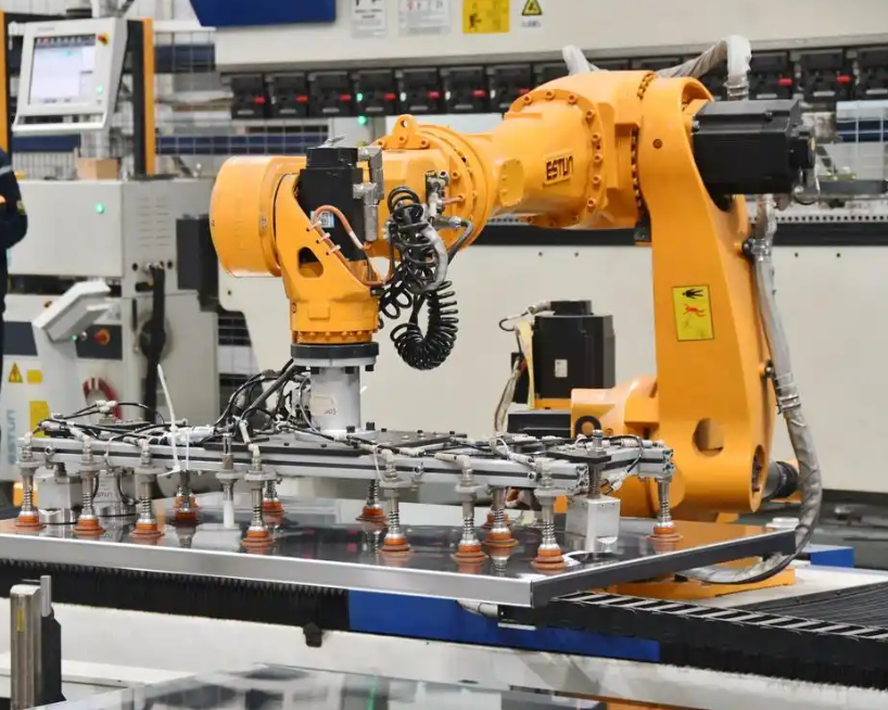
The system architecture can be summarized systematically. The perception layer performs image acquisition and target information extraction. The control layer performs grasping coordinate calculation, logic control, and operation monitoring. The execution layer performs workpiece grasping, transportation, and placement. I paid particular attention to the interfaces between these layers because the reliability of the industrial robot grasping system depends not only on the detection accuracy but also on the consistency of coordinate transformation and the synchronization of control signals. In my implementation, the vision detection result is first processed by the coordinate processing unit, which converts image coordinates into robot base coordinates. The PLC then reads these coordinates and generates motion commands for the industrial robot. The photoelectric sensor triggers the camera when a workpiece enters the detection area, and the PLC controls the conveyor belt to stop or start according to the state of the grasping cycle. The HMI monitoring module provides a visualization of the system status, including the detected workpiece category, the calculated grasping position, and the execution state of the industrial robot.
| Layer | Module | Function |
|---|---|---|
| Perception | Vision detection module | Collects images, detects workpiece category, and outputs target bounding box |
| Perception | Coordinate processing unit | Calculates target grasping coordinates from detection results |
| Control | Photoelectric sensor | Detects workpiece arrival and triggers image acquisition |
| Control | PLC control module | Receives coordinates and sensor signals, coordinates conveyor and industrial robot |
| Control | HMI monitoring module | Displays system status and supports operator monitoring |
| Execution | Six-axis industrial robot | Moves to the target position and performs the grasping motion |
| Execution | End effector | Air gripper or suction cup for different workpiece categories |
| Execution | Conveyor belt and placement unit | Transports workpieces and provides placement area |
The working process of my industrial robot grasping system is sequential and event-driven. When a workpiece enters the detection area, the photoelectric sensor detects its arrival and triggers the vision module to capture an image. The vision module then detects the workpiece and identifies its category. If the recognition fails, the system returns to the image acquisition step and retries. If the recognition succeeds, the system proceeds to target localization and grasping coordinate calculation. The PLC receives the grasping coordinates and issues control commands to make the industrial robot move to the grasping position. The end effector then performs either a clamping action or a suction action, depending on the workpiece category. After the workpiece is transported to the placement area and released, the system checks whether there is a next workpiece. If there is, the cycle repeats; if not, the system enters a waiting state. This workflow reduces the dependence on fixed-point teaching and improves the adaptability of the industrial robot to different workpieces and different placement states.
| Step | Action | Trigger or Condition |
|---|---|---|
| 1 | Workpiece enters detection area | Conveyor belt motion |
| 2 | Photoelectric sensor detects arrival | Workpiece blocks sensor |
| 3 | Vision module captures image | Sensor signal sent to PLC |
| 4 | YOLOv5 detection and classification | Image input |
| 5 | Recognition failure retry | Confidence below threshold or no target |
| 6 | Target localization and coordinate calculation | Successful recognition |
| 7 | PLC receives grasping coordinates | Coordinate processing completed |
| 8 | Industrial robot moves to target | PLC command |
| 9 | End effector grasps workpiece | Robot reaches grasping height |
| 10 | Workpiece placed and released | Robot reaches placement area |
| 11 | Next workpiece decision | PLC checks sensor and queue |
For image acquisition and sample construction, I performed all image collection within the conveyor belt detection area. The camera was mounted in a fixed top-down configuration, and the lens center was perpendicular to the working plane so that the detection area was fully within the field of view. The collected objects included four typical workpiece categories: block parts, disc parts, box parts, and planar parts. These categories cover the main grasping objects of the industrial robot in my experiments. During collection, I kept the camera installation height, shooting angle, and working plane reference unchanged to ensure a stable correspondence between image coordinates and the robot working area. I collected samples under normal illumination, weak illumination, slight deflection, position offset, and local occlusion. Image annotation used a uniform external rectangular bounding box, and the annotation content included the target category and the bounding box coordinates. The sample data were divided into a training set, a validation set, and a test set. The training set was used for model training, the validation set was used for parameter adjustment, and the test set was used for performance evaluation.
| Workpiece Category | Shape Characteristics | Typical Grasping Method |
|---|---|---|
| Block part | Clear boundary, significant thickness | Air gripper |
| Disc part | Circular outline, flat top surface | Suction cup |
| Box part | Rectangular boundary, uniform thickness | Air gripper |
| Planar part | Flat surface, large contact area | Suction cup |
| Dataset Split | Purpose | Condition Coverage |
|---|---|---|
| Training set | Model training | Normal illumination, weak illumination, slight deflection, position offset, local occlusion |
| Validation set | Parameter adjustment | Normal illumination, weak illumination, slight deflection |
| Test set | Performance evaluation | Normal illumination, weak illumination, slight pose disturbance |
For the AI visual detection model, I adopted YOLOv5 because it can simultaneously complete target classification and target localization in a single inference. This property is important for an industrial robot grasping system that requires real-time performance and detection accuracy. The model input is the workpiece image collected in the detection area, and the model output includes the target bounding box coordinates, the category label, and the confidence score. The bounding box coordinates describe the position range of the workpiece in the image. The category label distinguishes different types of workpieces. The confidence score evaluates the reliability of the detection result. To quantify the detection performance, I used precision, recall, and mean average precision as evaluation metrics. Their expressions are:
$$P = \frac{TP}{TP + FP}$$
$$R = \frac{TP}{TP + FN}$$
$$mAP = \frac{1}{N} \sum_{i=1}^{N} AP_i$$
In these equations, \(TP\) is the number of correctly detected targets, \(FP\) is the number of false detections, \(FN\) is the number of missed detections, \(AP_i\) is the average precision of the \(i\)-th target category, and \(N\) is the number of target categories. The single-target output form of the detection model can be expressed as:
$$B_i = (x_{1i}, y_{1i}, x_{2i}, y_{2i}, c_i, p_i)$$
Here, \((x_{1i}, y_{1i})\) and \((x_{2i}, y_{2i})\) are the coordinates of the upper-left and lower-right corners of the \(i\)-th target bounding box, respectively. \(c_i\) is the target category, and \(p_i\) is the detection confidence. During the detection stage, I filtered out results below a threshold and retained only valid targets that satisfied the grasping conditions. This filtering step is essential because the industrial robot should not attempt to grasp an object that is uncertain or outside the valid workspace.
| Metric | Definition | Role in My System |
|---|---|---|
| Precision \(P\) | \(TP / (TP + FP)\) | Measures how many detected targets are correct |
| Recall \(R\) | \(TP / (TP + FN)\) | Measures how many true targets are detected |
| Mean average precision \(mAP\) | Average of \(AP_i\) over all categories | Evaluates overall detection performance across multiple workpiece categories |
| Confidence \(p_i\) | Output score of YOLOv5 | Used to filter unreliable detections before grasping |
After target detection, the system must determine the grasping point from the bounding box. I used a bounding-box-center-based localization method. For block parts, box parts, and planar parts, I took the detection box center as the grasping point. For disc parts, I took the center of the external rectangular box as the localization point. Let the coordinates of the upper-left and lower-right corners of the target box be \((x_1, y_1)\) and \((x_2, y_2)\). The localization point \((x_c, y_c)\) is expressed as:
$$x_c = \frac{x_1 + x_2}{2}$$
$$y_c = \frac{y_1 + y_2}{2}$$
The target box width, height, and scale features are expressed as:
$$w = x_2 – x_1$$
$$h = y_2 – y_1$$
$$S = wh$$
Here, \(S\) is the target scale in the image, which can be used as an auxiliary quantity for multi-target sorting and grasping priority determination. In my implementation, the scale feature helps the industrial robot decide which target to grasp first when several workpieces are present in the detection area. A larger scale may indicate a closer or larger workpiece, while a smaller scale may indicate a farther or smaller workpiece. This information is useful for collision avoidance and for maintaining a stable grasping cycle.
For target coordinate transformation and grasping position determination, I used a fixed-camera visual guidance method. The camera was installed above the working table, and the industrial robot was located on one side of the conveyor belt grasping area. I defined the image pixel coordinate system \(O_p – x_p y_p\), the robot base coordinate system \(O_b – x_b y_b z_b\), and the end tool coordinate system \(O_t – x_t y_t z_t\). The image pixel coordinate system describes the target position in the image. The robot base coordinate system describes the motion position of the industrial robot in the workspace. The end tool coordinate system describes the installation relationship between the end effector and the flange. I used an eye-to-hand calibration method, in which the camera is fixed and the industrial robot moves within the camera field of view. During calibration, I selected several calibration points on the working plane, recorded their image pixel coordinates and their actual coordinates in the robot base coordinate system, and solved the coordinate transformation relationship from the image plane to the robot working plane. Because the grasping objects are located on the same working plane and the industrial robot uses a top-down grasping mode, the coordinate transformation mainly focuses on the planar position \(x\) and \(y\).
Let a point in the image coordinate system be:
$$P_p = \begin{bmatrix} u \\ v \\ 1 \end{bmatrix}$$
Its corresponding point in the robot plane coordinate system is:
$$P_r = \begin{bmatrix} x \\ y \\ 1 \end{bmatrix}$$
The relationship between them can be expressed as:
$$P_r = H P_p$$
where
$$H = \begin{bmatrix} a_{11} & a_{12} & a_{13} \\ a_{21} & a_{22} & a_{23} \\ 0 & 0 & 1 \end{bmatrix}$$
Here, \(H\) is the transformation matrix from image coordinates to robot plane coordinates, and its parameters are obtained from the calibration point data. To reduce calibration error, I used the least squares method to solve the matrix parameters. The objective function can be expressed as:
$$\min_H \sum_{i=1}^{n} \left( P_{r,i} – H P_{p,i} \right)^2$$
Through these steps, I established the mapping relationship between the image coordinates in the detection area and the robot grasping plane coordinates. This mapping is a key component of my industrial robot grasping system because it directly determines the accuracy of the final grasping position. If the mapping is inaccurate, even a perfect detection result will lead to a failed grasp. Therefore, I paid special attention to the calibration point selection, the camera installation stability, and the numerical solution of the transformation matrix.
| Coordinate System | Symbol | Description |
|---|---|---|
| Image pixel coordinate system | \(O_p – x_p y_p\) | Describes the target position in the image |
| Robot base coordinate system | \(O_b – x_b y_b z_b\) | Describes the industrial robot motion position in the workspace |
| End tool coordinate system | \(O_t – x_t y_t z_t\) | Describes the end effector installation relative to the flange |
After hand–eye calibration, I calculated the robot grasping coordinates according to the target localization point. Let the target center point output by the vision detection module be:
$$P_c = \begin{bmatrix} u_c \\ v_c \\ 1 \end{bmatrix}$$
Then the corresponding robot plane grasping position can be expressed as:
$$P_g = \begin{bmatrix} x_g \\ y_g \\ 1 \end{bmatrix} = H P_c$$
Here, \((u_c, v_c)\) is the target localization point coordinate in the image, and \((x_g, y_g)\) is the grasping coordinate in the robot working plane. During the grasping execution stage, the end pose of the industrial robot uses a fixed grasping posture, and the end normal is perpendicular to the working plane. The \(z\)-direction position is preset according to the workpiece height and the end effector structure. Therefore, the core of grasping position determination is the solution of the plane coordinates \(x_g\) and \(y_g\). For multi-target scenes, after coordinate transformation, I also performed an area constraint judgment. Let the effective grasping area of the industrial robot be:
$$\Omega = \left\{ (x, y) \mid x_{\min} \leq x \leq x_{\max}, \ y_{\min} \leq y \leq y_{\max} \right\}$$
When \((x_g, y_g) \in \Omega\), the target enters the grasping execution process. Otherwise, the target is not grasped. This area constraint prevents the industrial robot from attempting to reach an invalid position outside its workspace, which improves safety and reduces the risk of collision. In my experiments, the effective grasping area was determined by the robot reachable range and the conveyor belt layout. The area constraint also helps to reject false detections that may occur near the image boundary.
The grasping execution and control implementation are based on the coordination between the PLC and the industrial robot. The grasping execution stage takes the grasping coordinates as input and completes the operation in the sequence of approaching the target, descending to grasp, transporting and placing, and returning to the initial position. First, the industrial robot moves to a pre-grasp position above the target according to the grasping position parameters issued by the PLC. Second, the end effector descends vertically to a preset grasping height. Third, after the end effector reaches the grasping position, the end effector performs a clamping or suction action. Fourth, after the end effector completes the grasp, it transports the workpiece to the designated placement position and releases the workpiece, then returns to the initial position. The PLC is responsible for receiving the visual detection and coordinate processing results and coordinating the conveyor belt, photoelectric sensor, and industrial robot actions. When a workpiece enters the detection area, the photoelectric sensor sends an arrival signal to the PLC, and the PLC triggers the visual detection. After target localization and coordinate transformation are completed, the grasping coordinates are written into the PLC intermediate variables, and the PLC sends an execution command to the industrial robot. After the industrial robot completes the grasp and placement, it feeds the execution state back to the PLC, and the PLC controls the conveyor belt to transport the next workpiece. Through this process, the system realizes the sequential connection of detection, localization, coordinate transformation, and grasping execution.
| Stage | Industrial Robot Action | End Effector Action | PLC Coordination |
|---|---|---|---|
| Approach | Move to pre-grasp position above target | Keep open or inactive | Send grasping position parameters |
| Descend | Move vertically to grasping height | Prepare for grasp | Monitor motion completion |
| Grasp | Hold position | Clamp with air gripper or suction with cup | Receive grasp completion signal |
| Transport | Move to placement area | Keep workpiece secured | Coordinate conveyor state |
| Release | Hold position | Release or deactivate suction | Receive release completion signal |
| Return | Return to initial position | Reset to default state | Trigger next cycle if workpiece exists |
The end effector uses a combined air gripper and suction cup. The air gripper is suitable for block parts and box parts with clear boundaries and obvious thickness. The suction cup is suitable for disc parts and planar parts with relatively flat surfaces and large contact areas. The grasping method is determined according to the workpiece category information. When the detection result is a block part or a box part, the air gripper is used. When the detection result is a disc part or a planar part, the suction cup is used. This configuration can meet the grasping requirements of multiple workpiece categories. In my design, the end effector switching is controlled by the PLC through pneumatic valves, and the industrial robot program selects the corresponding grasping subroutine according to the category label received from the vision system.
| Workpiece Category | End Effector | Grasping Principle |
|---|---|---|
| Block part | Air gripper | Mechanical clamping on two opposite sides |
| Box part | Air gripper | Mechanical clamping with parallel jaws |
| Disc part | Suction cup | Vacuum adhesion on flat top surface |
| Planar part | Suction cup | Vacuum adhesion on large flat surface |
To verify the effectiveness of the industrial robot grasping system in target detection, coordinate transformation, and grasping execution, I built an experimental platform. The experimental platform consists of a vision detection module, a PLC control module, a conveyor belt unit, a photoelectric sensor, a six-axis industrial robot, and an end effector. The vision detection module is composed of an industrial camera and a vision processing unit. The industrial camera is installed above the detection area to collect workpiece images. The vision processing unit completes target detection and target localization. The PLC receives the detection results and coordinates the conveyor belt, sensor, and industrial robot actions. The industrial robot end is equipped with an air gripper and a suction cup to complete the grasping and placement of different workpieces. I selected four typical workpiece categories: block parts, disc parts, box parts, and planar parts. The experimental scenes were set to three working conditions: normal illumination, weak illumination, and slight pose disturbance. At the same time, workpieces entered the detection area in both single-target and multi-target modes. The experiments included target detection experiments, coordinate transformation experiments, and industrial robot grasping experiments. The evaluation indicators included recognition accuracy, average positioning error, maximum positioning error, grasping success rate, and single grasping time.
| Component | Specification or Role |
|---|---|
| Industrial camera | Fixed top-down installation above detection area |
| Vision processing unit | Runs YOLOv5 and target localization algorithms |
| PLC control module | Receives coordinates and coordinates conveyor, sensor, and industrial robot |
| Photoelectric sensor | Triggers image acquisition when workpiece arrives |
| Six-axis industrial robot | Performs grasping, transportation, and placement motions |
| End effector | Combined air gripper and suction cup |
| Conveyor belt unit | Transports workpieces into and out of the detection area |
| Experimental Condition | Description | Target Mode |
|---|---|---|
| Normal illumination | Standard factory lighting without strong shadows | Single-target and multi-target |
| Weak illumination | Reduced light intensity to test robustness | Single-target and multi-target |
| Slight pose disturbance | Small rotation or translation of workpiece | Single-target and multi-target |
In the target detection experiment, I performed 50 recognition tests for each of the four workpiece categories. The results showed that the overall recognition accuracy of the system under normal illumination was 96.5%. Under weak illumination, the overall recognition accuracy was 92.5%. Under slight pose disturbance, the overall recognition accuracy was 94.0%. Among the categories, block parts and disc parts had relatively stable recognition results. Box parts had a small number of missed detections under weak illumination. Planar parts showed a decrease in confidence when edge reflection occurred. These results indicate that the YOLOv5-based detection module can provide reliable category and position information for the industrial robot, but illumination conditions and surface reflection still affect performance.
| Illumination Condition | Overall Recognition Accuracy | Observed Issue |
|---|---|---|
| Normal illumination | 96.5% | Stable detection for all four categories |
| Weak illumination | 92.5% | Box parts had a small number of missed detections |
| Slight pose disturbance | 94.0% | Planar parts had reduced confidence under edge reflection |
In the coordinate transformation experiment, I selected 12 test points in the detection area and statistically analyzed the robot plane coordinates after mapping the visual localization points through the transformation matrix. The results showed that the average positioning error in the \(x\) direction was 1.42 mm, and the maximum error was 2.31 mm. The average positioning error in the \(y\) direction was 1.36 mm, and the maximum error was 2.08 mm. The comprehensive average plane error was 1.55 mm. The error mainly comes from calibration point extraction error, camera installation deviation, and target edge localization error. Although these errors are small, they can still affect the grasping success rate if the workpiece tolerance is tight. Therefore, I used the least squares method to solve the transformation matrix and repeated the calibration procedure to reduce systematic error.
| Direction | Average Positioning Error | Maximum Positioning Error |
|---|---|---|
| \(x\) direction | 1.42 mm | 2.31 mm |
| \(y\) direction | 1.36 mm | 2.08 mm |
| Comprehensive plane | 1.55 mm | 2.31 mm |
In the industrial robot grasping experiment, I performed 200 grasping tests on the four types of workpieces, with 50 tests for each type. The results showed that the comprehensive grasping success rate of the system was 94.5%. Among them, the grasping success rate of block parts was 96.0%, the grasping success rate of disc parts was 95.0%, the grasping success rate of box parts was 93.0%, and the grasping success rate of planar parts was 94.0%. The average time for a single grasp was 3.8 s. The main reasons for grasping failure were increased positioning deviation caused by weak illumination and interference between the end effector and adjacent workpieces caused by too small spacing in multi-target scenes. These failure modes suggest that future improvements should focus on illumination compensation, multi-target separation, and collision-aware motion planning.
| Workpiece Category | Number of Tests | Grasping Success Rate |
|---|---|---|
| Block part | 50 | 96.0% |
| Disc part | 50 | 95.0% |
| Box part | 50 | 93.0% |
| Planar part | 50 | 94.0% |
| Overall | 200 | 94.5% |
| Performance Indicator | Value |
|---|---|
| Comprehensive grasping success rate | 94.5% |
| Average single grasping time | 3.8 s |
| Average plane positioning error | 1.55 mm |
| Maximum plane positioning error | 2.31 mm |
To further verify the effectiveness of my method in recognition and grasping, I set up two groups of comparative experiments. The first group compared the traditional color recognition scheme with my detection scheme in a multi-category workpiece scene. The second group compared the grasping effect without coordinate transformation correction and with coordinate transformation correction. The comparison indicators included recognition accuracy, positioning error, and grasping success rate. In the visual recognition comparison experiment, the traditional color recognition method achieved overall recognition accuracy of 88.0% under normal illumination, 82.5% under weak illumination, and 84.0% under slight pose disturbance. My method achieved overall recognition accuracy of 96.5% under normal illumination, 92.5% under weak illumination, and 94.0% under slight pose disturbance. This comparison shows that the deep learning detector is more robust to illumination changes and pose variations than the color-based method.
| Method | Normal Illumination | Weak Illumination | Slight Pose Disturbance |
|---|---|---|---|
| Traditional color recognition | 88.0% | 82.5% | 84.0% |
| My YOLOv5-based method | 96.5% | 92.5% | 94.0% |
In the grasping coordinate solution comparison experiment, before coordinate transformation correction, the comprehensive average positioning error was 4.82 mm, the maximum error was 6.15 mm, and the grasping success rate was 86.0%. After coordinate transformation correction, the comprehensive average positioning error was reduced to 1.55 mm, the maximum error was reduced to 2.31 mm, and the grasping success rate was increased to 94.5%. The comparison results show that coordinate transformation correction can effectively reduce plane positioning error and improve the grasping success rate of the industrial robot. This is because the transformation matrix compensates for the misalignment between the image plane and the robot working plane, and it ensures that the detected target center is correctly projected into the robot base coordinate system.
| Case | Average Positioning Error | Maximum Positioning Error | Grasping Success Rate |
|---|---|---|---|
| Without coordinate transformation correction | 4.82 mm | 6.15 mm | 86.0% |
| With coordinate transformation correction | 1.55 mm | 2.31 mm | 94.5% |
From the experimental results, I can draw several important conclusions about my industrial robot grasping system. First, the detection module can stably output workpiece category and position information. The YOLOv5 model provides a good balance between speed and accuracy, and it is suitable for real-time industrial robot grasping tasks. Second, the coordinate transformation result satisfies the requirements of regular workpiece grasping. The average plane error of 1.55 mm is acceptable for many industrial applications, especially when the end effector has a certain tolerance. Third, the system can complete continuous grasping tasks under normal operating conditions. The comprehensive grasping success rate of 94.5% and the average single grasping time of 3.8 s indicate that the system has good practical potential.
The error sources in my system can be summarized as follows. Calibration point extraction error arises because the calibration points are manually selected or automatically detected with limited precision. Camera installation deviation occurs if the camera is not perfectly perpendicular to the working plane or if the camera position changes slightly after calibration. Target edge localization error comes from the bounding box regression of the YOLOv5 model, especially when the workpiece edge is blurred or reflective. Weak illumination increases the difficulty of edge detection and reduces the confidence of the detector. Multi-target interference occurs when workpieces are placed too close to each other, causing the end effector to collide with an adjacent workpiece. These error sources are not independent; they can accumulate and lead to grasping failure.
| Error Source | Cause | Effect on Grasping |
|---|---|---|
| Calibration point extraction error | Limited precision of calibration point selection | Systematic offset in coordinate transformation |
| Camera installation deviation | Non-perpendicular mounting or post-calibration movement | Plane mapping distortion |
| Target edge localization error | Blurred or reflective workpiece edges | Inaccurate grasping point |
| Weak illumination | Low contrast and reduced detector confidence | Missed detection or increased positioning deviation |
| Multi-target interference | Small spacing between workpieces | End effector collision and grasp failure |
The limitations of my current work should also be acknowledged. The research objects are mainly limited to regular workpieces in a two-dimensional plane. I did not consider complex occlusion, three-dimensional pose changes, or dynamic grasping conditions. In real manufacturing environments, workpieces may be stacked, tilted, or moving on a conveyor belt. These situations require more advanced pose estimation and motion planning. In addition, the current system uses a fixed grasping posture, which is suitable for top-down grasping but not for side grasping or multi-angle grasping. The end effector switching is based on category labels, and it does not adapt to unexpected shape variations within the same category.
For future work, I plan to extend the system in several directions. First, I will investigate complex scene pose estimation using RGB-D cameras or stereo vision, so that the industrial robot can grasp workpieces with three-dimensional pose changes. Second, I will optimize the grasping strategy by introducing collision-aware motion planning and dynamic target tracking. Third, I will improve the real-time control performance by reducing the communication latency between the vision processing unit and the PLC. Fourth, I will explore domain adaptation and data augmentation to improve the detection robustness under different illumination and background conditions. These improvements would make the industrial robot grasping system more flexible and more suitable for complex manufacturing scenarios.
In conclusion, I constructed an industrial robot grasping system based on AI visual detection and localization. The system integrates visual detection, target localization, coordinate transformation, and grasping execution. I used YOLOv5 for workpiece recognition and target localization, applied hand–eye calibration to convert image coordinates into robot plane coordinates, and combined a PLC, a six-axis industrial robot, and an air gripper or suction cup end effector to complete the grasping execution. The experimental results show that the system can stably complete multi-category workpiece recognition, plane position solving, and grasping operations. The overall recognition accuracy reached 96.5% under normal illumination, 92.5% under weak illumination, and 94.0% under slight pose disturbance. The comprehensive average plane positioning error was 1.55 mm. The comprehensive grasping success rate for 200 grasping experiments on four types of workpieces was 94.5%, and the average single grasping time was 3.8 s. These results indicate that my method has good feasibility and application value in regular workpiece grasping scenarios. The industrial robot can benefit from this integrated approach because it reduces the dependence on fixed-point teaching and improves adaptability to multi-category workpieces and changing placement positions.