
When I first stood in front of a class of second-year engineering students and asked them to write a simple pick-and-place program for an industrial robot, I expected enthusiasm. What I received instead was a room full of hesitant faces, a handful of students copying syntax from a slide, and a collective assumption that the correct answer already existed somewhere and merely had to be recalled. That moment convinced me that the problem was not the students. The problem was the architecture of the course I was delivering. The subject matter of industrial robot application programming is inherently dynamic, spatial, iterative, and unforgiving of purely theoretical knowledge. Yet my teaching had been organized as a linear sequence of definitions, command lists, and demonstration videos, capped by a written examination that rewarded memorization far more than competence.
This article documents the redesign that followed. I rebuilt the course around the Conceive–Design–Implement–Operate (CDIO) framework, and I describe here what the redesign looked like in practice, how I implemented it inside a real teaching cell with real industrial robot hardware, what quantitative evidence emerged from a two-cohort comparison, and what remains unresolved. My intention is not to present CDIO as a universal remedy. Rather, I want to show how a specific engineering education philosophy was translated into concrete teaching decisions for a specific course, and how those decisions changed what my students could actually do at the end of a semester.
1. The Context That Forced a Change
The manufacturing environment my graduates enter is saturated with automation. Industrial robot installations continue to rise across welding, palletizing, assembly, machine tending, inspection, and logistics. What employers repeatedly tell me is that they do not struggle to find people who can recite the difference between joint space and Cartesian space. They struggle to find people who can walk onto a shop floor, read an existing industrial robot program, diagnose why a trajectory is overshooting, adjust a tool frame, re-teach a waypoint set, and hand the cell back to production without a supervisor standing beside them.
That gap between declarative knowledge and operational capability is the central problem the CDIO framework addresses. CDIO was developed in engineering education specifically to close the distance between the classroom and the engineering workspace by organizing learning around the complete lifecycle of a product, process, or system. For an industrial robot course, this lifecycle is remarkably natural to map, because the deployment of any industrial robot application genuinely does proceed through conception, design, implementation, and operation.
I should state my own starting assumptions plainly, because they shaped every subsequent decision:
First, competence in industrial robot programming is not transmitted; it is constructed through repeated encounters with problems that resist immediate solution. Second, the emotional experience of failure inside a supervised teaching cell is pedagogically valuable and should be designed for rather than avoided. Third, assessment must measure the same capabilities that industry values, otherwise students will rationally optimize for whatever the assessment rewards. Fourth, group work is not a convenience for reducing instructor workload; it is a deliberate rehearsal of the communication patterns that industrial robot integration projects require.
2. The CDIO Framework as I Applied It
CDIO is often summarized as four verbs, which risks making it sound trivial. In my own planning I treated it as four distinct epistemic positions that a learner must occupy with respect to a problem, each with its own characteristic questions, artifacts, and failure modes.
2.1 The Four Stages in Operational Terms
| Stage | Guiding Question | Typical Student Activity | Artifact Produced | Characteristic Failure |
|---|---|---|---|---|
| Conceive | What problem are we actually solving, and for whom? | Requirement elicitation, cycle time analysis, payload and reach specification, risk listing | Requirement specification, concept sketch, feasibility note | Solving the wrong problem; accepting an unstated constraint |
| Design | How should the industrial robot system be structured? | Kinematic configuration, gripper selection, frame definition, program architecture, safety zoning | Design document, I/O map, program flow chart, simulation model | Designing something that cannot be built or debugged |
| Implement | Can we make it actually work? | Hardware assembly, wiring, teaching points, program coding, incremental commissioning | Working industrial robot cell, commented program, test log | Integrating without a test strategy; undocumented changes |
| Operate | Does it work reliably under real conditions? | Cycle time measurement, repeatability checks, fault injection, handover documentation | Performance report, optimization record, operating manual | Declaring success after a single successful run |
The table above became the backbone of my syllabus. Every project module my students undertake passes through all four columns, and the artifact column became the actual deliverable list for grading.
2.2 Why This Framework Suits an Industrial Robot Course
An industrial robot application is never merely a program. It is a coupled system comprising a manipulator, a controller, a tool, a workpiece presentation method, a sensing strategy, a safety envelope, and a human operator. Each of these elements imposes constraints on the others. A gripper selected during the design stage determines whether a taught waypoint is reachable. A cycle time target stated during conception determines whether a particular trajectory interpolation method is acceptable. A safety zoning decision made during implementation may invalidate a motion plan developed during design.
Traditional lecture sequencing hides these couplings. A lecturer discusses coordinate frames on Monday, grippers on Wednesday, and motion instructions on Friday, and the student never observes that these decisions are entangled. CDIO forces the entanglement into the open because students must produce a single coherent system, and a single coherent system cannot tolerate independently made, mutually incompatible decisions.
The framework also offers a natural answer to a question I had struggled with for years: how do I justify spending three weeks on a project when the textbook contains forty more pages of commands? The answer is that command recall is cheap and re-learnt quickly by anyone who understands the system, while system-level reasoning is expensive and decays quickly if not exercised. CDIO explicitly prioritizes the expensive capability.
2.3 Comparison With the Approach I Had Been Using
| Dimension | Previous Practice | CDIO-Based Practice |
|---|---|---|
| Locus of authority | Instructor holds the correct procedure | Requirements and physical constraints hold authority |
| Sequence | Topic-by-topic, discipline-organized | Project-by-project, lifecycle-organized |
| Typical task | Reproduce a demonstrated program | Specify, build, commission, and document a cell |
| Student role | Receiver and imitator | Designer, integrator, and operator |
| Failure treatment | Failure is a deduction | Failure is diagnostic information |
| Assessment focus | Recall of syntax and definitions | Demonstrated capability plus reasoning artifacts |
| Peer interaction | Incidental | Structured and assessed |
| Documentation | Optional or absent | Mandatory deliverable at each stage |
3. Diagnosing My Own Course Before Redesign
Before changing anything I spent a semester systematically recording where learning broke down. I kept a teaching log, collected examination item statistics, interviewed twelve graduates at various stages of their careers, and reviewed the comments of employer supervisors who hosted our interns. Four recurring patterns emerged.
3.1 Content Drifted From Practice
The sequence of topics I taught had accreted over years and reflected what was convenient to teach rather than what was needed in the field. My examples were drawn from an idealized cell with generous clearance, uniform workpieces, and no human intrusion. Real cells are crowded, tolerate variance poorly, and must be designed around human presence. Students who could solve a clean kinematic problem in an examination were unable to handle a cluttered workspace layout.
3.2 Practical Work Was Confirmatory Rather Than Generative
My laboratory sessions had a fixed outcome. Students followed a worksheet, taught four points, pressed run, observed success, and left. Because no genuine uncertainty existed, no genuine problem-solving occurred. Worse, students who made an error simply asked a neighbor for the correct number rather than investigating why their own number was wrong.
3.3 Instruction Was Monologic
My lectures were well prepared and clearly delivered, and that was precisely the problem. Clarity of delivery created a passive competence illusion. Students could follow my reasoning in real time and therefore believed they owned it, an illusion that collapsed the moment they had to generate reasoning without me.
3.4 Assessment Measured the Wrong Construct
My final examination was heavily weighted toward definitions, command syntax, and short kinematic calculations. Documenting and reasoning were not assessed. Consequently, my students behaved exactly as the incentive structure predicted: they memorized, and they neglected documentation, teamwork, and systematic debugging.
| Observed Symptom | Underlying Cause | Consequence for Graduates |
|---|---|---|
| High examination marks, low commissioning confidence | Assessment separated from performance | Supervisors report a long ramp-up period |
| Students ask for the answer rather than investigate | Labs had no genuine uncertainty | Weak diagnostic reasoning |
| Excellent individual work, poor handover quality | No documentation requirement | Integration teams lose time reconstructing intent |
| Strong on isolated commands, weak on system structure | Discipline-organized sequence | Difficulty scaling to multi-station cells |
4. Designing the CDIO-Based Course
The redesign proceeded in five parallel tracks: objectives, content, process, methods, and assessment. I treated these as mutually constraining rather than sequential, because changing assessment without changing content merely relabels the same course.
4.1 Learning Objectives
I wrote objectives so that each one could be observed in a student artifact. This requirement eliminated several aspirational statements I had previously used, such as “understand the importance of industrial robot safety,” which cannot be observed directly and therefore cannot be graded meaningfully.
| Domain | Objective | Observable Evidence |
|---|---|---|
| Knowledge | Explain the structure, drive architecture, and control hierarchy of a typical industrial robot | Written design rationale referencing joint types and controller architecture |
| Knowledge | Interpret and write programs using motion, logic, I/O, and frame instructions | Commented program listing that executes correctly |
| Capability | Plan trajectories that satisfy reachability, singularity, and cycle time constraints | Simulation record plus measured cycle time |
| Capability | Commission an industrial robot cell from an incomplete specification | Working cell demonstrated under observation |
| Capability | Diagnose and correct faults systematically | Fault log showing hypothesis-test-correction cycles |
| Attitude | Document work so that another engineer can resume it | Handover manual evaluated by a peer unfamiliar with the project |
| Attitude | Contribute constructively within a technical team | Peer assessment plus contribution record |
4.2 Content Modularization
I reorganized the syllabus into six project modules of increasing coupling. The early modules isolate a small number of variables; the later modules deliberately introduce conflicting constraints. The sequence matters because students need a stable foothold before they can tolerate ambiguity.
| Module | Industrial Robot Task | Dominant New Constraint | Integrated Prior Knowledge |
|---|---|---|---|
| M1 | Single-station pick and place | Frame definition and tool centre point calibration | Basic motion instructions |
| M2 | Palletizing and depalletizing | Pattern generation and stacking tolerance | Coordinate transformation, looping logic |
| M3 | Arc welding path following | Path continuity and process parameter coupling | Trajectory interpolation, I/O handshaking |
| M4 | Vision-guided sorting | Perception latency and pose uncertainty | Conditional branching, error handling |
| M5 | Precision assembly with force feedback | Compliant motion and search strategies | Sensor integration, state machines |
| M6 | Multi-station line with buffer and handshake | Cycle time balance and fault recovery | Everything above |
Notice that module six cannot be completed by a student who has merely memorized modules one through five. It requires selecting among competing approaches, which is precisely the generative capability the framework is intended to develop.
4.3 Process Design
Each module follows the same four-phase rhythm, but the amount of instructor scaffolding decreases across the semester. In module one I supply a nearly complete requirement specification. By module six students must produce the specification themselves from a brief conversation with a simulated customer.
| Phase | Instructor Action | Student Action | Time Allocation |
|---|---|---|---|
| Conceive | Present a task brief with deliberate omissions | Elicit requirements, quantify constraints, list risks | 10 percent |
| Design | Review design documents, challenge assumptions | Select configuration, define frames, architect program | 25 percent |
| Implement | Supervise cell access, intervene only on safety | Assemble, wire, teach, code, commission | 45 percent |
| Operate | Observe demonstration, question performance claims | Measure, optimize, document, hand over | 20 percent |
4.4 Teaching Methods
I used four methods in combination. Project-driven instruction supplied the organizing spine. Team-based learning supplied the social structure, with teams of four and rotating technical lead roles so that no student could hide behind a dominant peer. Blended delivery moved declarative content out of class time, using short recorded explanations of instruction syntax and frame mathematics that students viewed before arriving. Deliberate fault injection, the fourth method, was the one I considered most distinctive: at planned intervals I introduced a fault into a working cell, such as an incorrect tool frame, a mis-set payload, or a reversed limit switch, without announcing it, and required teams to diagnose it using a written hypothesis-test log.
Deliberate fault injection deserves emphasis because it targets the capability employers described as scarcest. Reading a program is easy; determining why a working program has stopped working is hard, and it is almost never taught explicitly. By the end of the semester my students had diagnosed an average of eleven injected faults per team.
4.5 Assessment Design
I allocated sixty percent of the final mark to continuous evidence and forty percent to a terminal demonstration plus written examination. Continuous evidence was itself decomposed into several weighted components.
$$S_{total} = \alpha \sum_{i=1}^{n} w_i S_i^{process} + \beta \left( \gamma S_{demo} + \delta S_{exam} \right)$$
where the process components are indexed by module and the weights satisfy the normalization and non-negativity conditions
$$\sum_{i=1}^{n} w_i = 1, \qquad w_i \geq 0, \qquad \alpha + \beta = 1, \qquad \gamma + \delta = 1$$
In the delivered course I set $\alpha = 0.6$, $\beta = 0.4$, $\gamma = 0.6$, and $\delta = 0.4$. The module weights were biased toward later modules to reflect increasing integration difficulty.
| Component | Share of Process Mark | Evidence Used |
|---|---|---|
| Module 1 documentation and demonstration | 8 percent | Requirement note, working cell, program listing |
| Module 2 documentation and demonstration | 10 percent | Palletizing pattern generator, cycle time log |
| Module 3 documentation and demonstration | 13 percent | Welding path record, parameter justification |
| Module 4 documentation and demonstration | 15 percent | Vision integration report, uncertainty handling |
| Module 5 documentation and demonstration | 18 percent | Assembly strategy, force feedback trace |
| Module 6 documentation and demonstration | 24 percent | Full line commissioning, handover manual |
| Fault diagnosis log | 7 percent | Hypothesis-test-correction records |
| Peer and self assessment | 5 percent | Contribution record, reflective statement |
Because documentation carried explicit weight, I had to define what acceptable documentation meant. Vague instructions such as “document your work” produce vague artifacts. I therefore published a rubric with observable criteria.
| Criterion | Insufficient | Developing | Proficient | Exemplary |
|---|---|---|---|---|
| Requirement traceability | No requirements stated | Requirements listed but unlinked to design | Each design decision traced to a requirement | Traceability maintained through to measured performance |
| Program structure | Monolithic, uncommented | Some modularity, sparse comments | Modular with named subroutines and comments | Modular, parameterized, portable across similar cells |
| Diagnostic reasoning | Guessing and random changes | Sequential trial without hypotheses | Explicit hypotheses tested one variable at a time | Systematic elimination with documented reasoning |
| Performance evidence | No measurements | Single measurement reported | Repeated measurements with variability noted | Measurements linked to optimization decisions |
| Handover quality | Unusable by another engineer | Usable with verbal explanation | Usable independently by a peer | Usable by a peer unfamiliar with the project |
5. Implementation in the Teaching Cell
5.1 Physical and Human Preparation
Implementation required simultaneous preparation of infrastructure, resources, and my own practice. On the infrastructure side I needed enough workstations that teams could work in parallel without queueing, a safe enclosure with interlocks, a vision sensor capable of delivering unreliable data so that uncertainty handling could be taught authentically, and a force sensing capability for the assembly module. Interlocks and emergency stops were treated as non-negotiable prerequisites rather than teaching content, because safety systems that students bypass do not teach safety.
On the resource side I prepared a library of task briefs, each deliberately incomplete in a different way. One brief omits the cycle time target, another omits the workpiece variance, a third omits the human access requirement. Teams must identify the omission, request the missing information, and justify their estimate if the customer is unavailable. This small design choice transformed the conceive phase from a formality into a genuine engineering act.
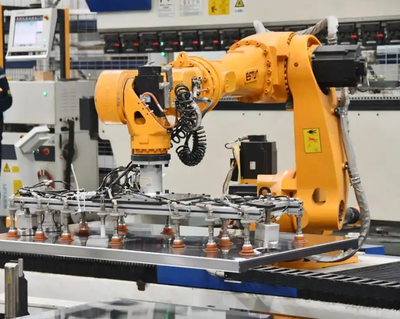
On the human side I had to change my own behaviour substantially. In the previous course my natural instinct during laboratory time was to walk to a struggling team and explain the solution. In the redesigned course I adopted a rule: I would answer a direct technical question only after the team had written the question down and recorded at least one hypothesis. Initially this felt obstructive, and several students complained. By mid-semester the complaints stopped, because teams began arriving with sharper questions and, increasingly, with answers they had already found.
5.2 A Detailed Example: The Palletizing Module
To make the design concrete I will describe the palletizing module in the level of detail with which students encounter it. The brief states that a carton of known mass must be transferred from a conveyor to a pallet in a specified pattern, that the pallet must be exchanged by a human operator, and that the cycle must complete within a stated time. The brief omits the carton dimension tolerance and the required stacking accuracy, which teams must negotiate.
During the conceive phase teams compute reachability. For a manipulator with link parameters, the position of the tool centre point relative to the base is obtained from the chain of homogeneous transformations
$$T_i^{\,i-1} = \begin{bmatrix} c\theta_i & -s\theta_i c\alpha_i & s\theta_i s\alpha_i & a_i c\theta_i \\ s\theta_i & c\theta_i c\alpha_i & -c\theta_i s\alpha_i & a_i s\theta_i \\ 0 & s\alpha_i & c\alpha_i & d_i \\ 0 & 0 & 0 & 1 \end{bmatrix}$$
with the shorthand notation $c(\cdot) = \cos(\cdot)$ and $s(\cdot) = \sin(\cdot)$, and the complete forward kinematic map given by the ordered product
$$T_{base}^{tool} = \prod_{i=1}^{m} T_i^{\,i-1}$$
Reachability for every taught waypoint $\mathbf{p}_j$ then becomes the feasibility condition
$$\left\| \mathbf{p}_j – \mathbf{p}_{base} \right\| \leq R_{max} – \varepsilon_{margin}$$
where the margin $\varepsilon_{margin}$ accounts for the wrist offset and the need to avoid a fully extended singular posture. Teams that ignore this margin produce programs that run successfully in simulation and fault intermittently on hardware, which is exactly the lesson the module is designed to deliver.
During the design phase teams generate the pallet pattern algorithmically rather than teaching every point, producing a nested loop over rows and columns
$$\mathbf{p}_{r,c} = \mathbf{p}_{origin} + r\,\Delta_y \,\hat{\mathbf{y}} + c\,\Delta_x \,\hat{\mathbf{x}} + h_{layer}\,\hat{\mathbf{z}}$$
and selecting motion types so that approach and departure segments are linear while transfer segments are joint-interpolated for speed. Cycle time is estimated as the sum of segment times and then compared with the target
$$T_{cycle} = \sum_{j=1}^{m} \left( t_j^{move} + t_j^{wait} + t_j^{grip} \right) \leq T_{target}$$
Most teams initially overshoot the target and must decide whether to shorten the transfer path, increase velocity scaling, reduce the number of intermediate waypoints, or reorient the pallet. Each option has a cost in accuracy or safety, so the decision requires justification rather than mere adjustment.
During the implement phase the gripper is mounted, the tool centre point is calibrated, the payload mass and centre of gravity are entered into the controller so that dynamic compensation is valid, and the program is commissioned incrementally. I require incremental commissioning: one waypoint per run, verified, then extended. Teams that attempt to run an entire untested program generate collisions and lose more time than they save.
During the operate phase teams measure actual cycle time over a run of at least fifty cycles, compute the deviation from the target, and produce
$$\sigma_{T} = \sqrt{\frac{1}{N-1}\sum_{k=1}^{N}\left(T_k – \bar{T}\right)^2}$$
which almost always reveals variability larger than the teams expect. Investigating the source of that variability, whether carton slip, grip delay, or approach overshoot, is where most genuine learning occurs. Finally, a peer from another team who has never seen the project must complete a pallet change using only the written handover manual, and any assistance required is recorded as a documentation defect.
5.3 The Semester Timeline
| Week | Focus | Deliverable at Week End |
|---|---|---|
| 1 to 2 | Cell orientation, safety, frame mathematics, tool centre point calibration | Calibration record for a specified tool |
| 3 to 4 | Module 1, single-station transfer | Working cell plus requirement note |
| 5 to 6 | Module 2, palletizing | Pattern generator plus measured cycle time |
| 7 to 8 | Module 3, welding path following | Path record plus parameter justification |
| 9 to 10 | Module 4, vision-guided sorting | Integration report plus uncertainty analysis |
| 11 to 12 | Module 5, compliant assembly | Strategy document plus force trace |
| 13 to 14 | Module 6, integrated line | Commissioned line plus handover manual |
| 15 to 16 | Demonstration, peer handover trial, examination | Final portfolio |
6. What the Evidence Showed
6.1 Comparison Design
I compared two intact cohorts of the same programme, taught by me in consecutive years with the same contact hours and the same laboratory equipment. The earlier cohort experienced the previous lecture-centred course. The later cohort experienced the CDIO-based course described above. Cohort sizes were $n_1 = 41$ and $n_2 = 39$. Because assignment was not randomized, I treat the comparison as indicative rather than causal, and I report it in that spirit. Both cohorts took the same written examination, which I deliberately kept unchanged so that any difference in that measure would not be an artifact of a new examination design. Practical capability was assessed with a common commissioning task scored by two raters using the rubric described earlier.
6.2 Practical Performance
For each cohort I computed the mean and standard deviation on the commissioning task, and I computed the standardized mean difference using the pooled standard deviation
$$s_p = \sqrt{\frac{(n_1 – 1)s_1^2 + (n_2 – 1)s_2^2}{n_1 + n_2 – 2}}, \qquad d = \frac{\bar{X}_2 – \bar{X}_1}{s_p}$$
| Measure | Previous Cohort, Mean | Previous Cohort, SD | CDIO Cohort, Mean | CDIO Cohort, SD | Standardized Difference |
|---|---|---|---|---|---|
| Commissioning task total | 68.4 | 11.2 | 81.7 | 9.6 | 1.28 |
| Requirement traceability | 5.9 | 2.1 | 8.2 | 1.7 | 1.21 |
| Program structure | 13.1 | 3.4 | 16.8 | 2.9 | 1.17 |
| Diagnostic reasoning | 11.6 | 3.8 | 16.1 | 3.1 | 1.30 |
| Performance evidence | 7.2 | 2.6 | 10.4 | 2.2 | 1.33 |
| Handover quality | 6.5 | 2.4 | 9.7 | 2.0 | 1.44 |
| Written examination | 71.8 | 12.6 | 74.9 | 11.9 | 0.25 |
The pattern is informative. The largest differences appear on the dimensions the redesigned assessment explicitly rewarded, particularly handover quality and diagnostic reasoning. The written examination, which neither cohort experienced differently in preparation incentives beyond the general course change, shows only a small difference. This is consistent with my expectation that the CDIO redesign mainly changes what students can do rather than what they can recite, and it also suggests that the previous course was not failing to transmit knowledge, it was failing to develop capability.
6.3 Normalized Learning Gain
To account for the fact that students entered with different starting competence, I administered a short capability self-report and a short diagnostic exercise at the beginning and end of the semester, and computed the normalized gain
$$g = \frac{S_{post} – S_{pre}}{S_{max} – S_{pre}}$$
| Dimension | Previous Cohort Gain | CDIO Cohort Gain |
|---|---|---|
| Frame and tool centre point reasoning | 0.21 | 0.48 |
| Trajectory and cycle time reasoning | 0.17 | 0.44 |
| Fault diagnosis | 0.12 | 0.52 |
| Documentation and handover | 0.09 | 0.46 |
| Team coordination | 0.15 | 0.39 |
The diagnosis and documentation dimensions show the largest normalized gains, which aligns with the emphasis of the redesign. The team coordination gain is real but more modest, which I attribute to the fact that coordination skill develops over longer periods than a single semester.
6.4 Student Perceptions
I administered an anonymous perception survey at the end of the CDIO semester with a five-point Likert scale. Internal consistency was acceptable.
$$\alpha_{Cronbach} = \frac{k}{k-1}\left(1 – \frac{\sum_{i=1}^{k}\sigma_i^2}{\sigma_T^2}\right)$$
| Survey Item | Mean | SD |
|---|---|---|
| The project structure helped me see how knowledge from different topics connects | 4.41 | 0.61 |
| I became more confident working with an industrial robot independently | 4.28 | 0.72 |
| The graduated difficulty of the modules kept me engaged | 4.05 | 0.83 |
| The documentation requirements made my work more professional | 3.92 | 0.91 |
| The complexity of the final module was challenging in a useful way | 4.17 | 0.79 |
| I found the amount of self-directed work excessive | 3.46 | 1.05 |
| I would prefer more instructor demonstration in future modules | 3.31 | 1.12 |
The two lowest-scoring items are both complaints, and I want to report them because they are the honest counterweight to the positive results. A meaningful minority of students experienced the self-directed workload as excessive and wanted more demonstration. Their grievance is legitimate. The transition from a lecture-centred course to a project-centred course shifts cognitive load onto students, and not all students are prepared for that shift at the same rate. In the following iteration I added an optional weekly clinic in which I demonstrated a technique without solving anyone’s project, which reduced the sense of abandonment without restoring the old dynamic.
6.5 Observations That Numbers Do Not Capture
Three qualitative changes struck me more than any score. First, the vocabulary of the classroom changed. Students began to speak about their cell in terms of requirements, constraints, and evidence rather than in terms of correct and incorrect answers. Second, peer teaching became visible and voluntary; teams working on module five were routinely approached by teams from module four, and I frequently observed a student explaining a frame transformation at a whiteboard without any instructor prompting. Third, and most gratifying, several students began arriving with problems they had discovered on their own rather than problems I had assigned, which is the clearest sign I know that a course has shifted from transmission to inquiry.
7. Difficulties and How I Addressed Them
| Difficulty | Observable Effect | Adjustment Made |
|---|---|---|
| Uneven team contribution | Two students dominate, two disengage | Rotating technical lead plus granular contribution records |
| Documentation perceived as low value | Rushed or copied reports | Peer handover trial that fails when documentation is weak |
| Hardware access bottlenecks | Waiting time during implement phase | Simulation first, then scheduled cell slots with staggered rotation |
| Assessment workload | Rater fatigue and inconsistency | Single-page rubric with four levels, blind double rating for final projects |
| Student anxiety at reduced guidance | Requests for a complete answer | Weekly optional technique clinic, question-after-hypothesis rule |
| Fault injection fairness | Some teams deemed faults unfair | Published inventory of fault categories in advance |
The fairness objection to fault injection deserves a note. Early in the first iteration some teams argued that an injected fault they could not have anticipated was an unfair assessment. I responded by publishing the categories of faults that could be injected, without revealing which specific fault was present in any given run. This preserved the diagnostic challenge while removing the sense of arbitrariness, and complaints essentially disappeared.
I also learned to be careful about the order in which I intervene. My natural instinct, when a team’s industrial robot executes an unexpected motion, is to reach for the teach pendant. Suppressing that instinct is difficult but necessary. The moment I touch the pendant, the team becomes spectators to their own project.
8. Ongoing Refinement
No teaching design is finished, and I want to be explicit about what remains weak in mine.
First, my industrial robot inventory is smaller than I would like relative to cohort size. Scarcity of hardware inevitably produces queueing, and queueing subtly rewards fast workers and penalizes reflective ones. Additional cells would allow more parallel work and would allow me to introduce more complex multi-robot coordination tasks.
Second, my teaching resources are uneven. The task briefs vary in quality, and the fault library, though growing, is still thin in the areas of fieldbus communication faults and safety circuit faults, which are common in real commissioning.
Third, my own competence in some areas remains the limiting factor. Force-controlled assembly and vision-guided handling evolve quickly, and I need sustained industry engagement to keep the modules authentic. I have begun arranging short placement periods for myself in integration companies during non-teaching periods, which is uncomfortable but necessary.
Fourth, the assessment of teamwork remains the least reliable component. Contribution records and peer ratings are easy to game, and I have not yet found a design that measures collaboration without rewarding visibility over substance.
| Improvement Area | Specific Action | Expected Benefit |
|---|---|---|
| Hardware capacity | Add two additional teaching cells with interchangeable tooling | Reduce queueing, enable parallel modules |
| Fault library | Expand to include communication and safety circuit faults | Better alignment with real commissioning |
| Instructor currency | Periodic industry placement for teaching staff | Modules reflect current practice |
| Teamwork measurement | Introduce artefact-based contribution evidence | Reduce gaming of peer ratings |
| Threshold concepts | Identify and target the concepts that block most teams | Faster recovery for struggling students |
| Longitudinal tracking | Follow graduates for three years post-completion | Validate that capability persists |
9. Reflections on the Framework
Three reflections summarize what I have taken from this work. The first is that CDIO is not a template. The four stages are the least interesting part of the framework. What matters is that each stage imposes a distinct discipline on student thinking: conceive forces justification of the problem, design forces commitment to a structure, implement forces contact with physical reality, and operate forces accountability for performance. Remove any one of these disciplines and the framework collapses into conventional project work.
The second reflection concerns the relationship between structure and freedom. I initially believed that a project-based course meant stepping back and letting students find their own way. That was wrong, and the first iteration was chaotic as a result. Students needed tighter structure than before, not looser structure, but of a different kind: structure in the process and the deliverables, freedom in the technical solution. The table of artifacts per stage became that structure, and once it existed, the freedom became productive rather than disorienting.
The third reflection is about the industrial robot itself. A manipulator is an unusually honest teaching object. It cannot be persuaded, it does not accept a plausible-sounding explanation, and it will faithfully execute an incorrect command and collide with whatever is in the way. That honesty is pedagogically precious. When a student’s reasoning is wrong, the industrial robot demonstrates the error physically, immediately, and without judgment. No lecture can produce that quality of feedback. The whole purpose of the CDIO redesign was to put students in direct contact with that feedback as often as possible, and to surround it with the documentation, reasoning, and collaboration practices that turn a collision into a durable lesson.
10. Conclusion
I redesigned an industrial robot application programming course around the CDIO framework because the previous design, however clearly delivered, produced graduates who could describe industrial robot programming but could not reliably perform it. The redesign reorganized objectives so that each was observable, restructured content into six project modules with deliberately increasing coupling, replaced the lecture rhythm with a four-phase lifecycle rhythm, introduced project-driven and team-based methods alongside deliberate fault injection, and rebuilt assessment so that documentation, diagnosis, and handover carried real weight.
Across a two-cohort comparison, the CDIO-based course produced substantially higher performance on commissioning tasks, with standardized differences near or above one on every practical dimension, while producing only modest improvement on a written examination that the redesign did not primarily target. Normalized learning gains were largest for fault diagnosis and documentation, the two dimensions most neglected by the previous design. Student perception was largely positive, with an honest minority reporting that the self-directed workload was excessive, a complaint I take seriously and have partially addressed.
The conclusion I draw is not that CDIO is uniquely correct. It is that the alignment between what a course assesses, what it asks students to do, and what the profession requires is the variable that matters most, and that the CDIO framework provides a durable way of achieving that alignment for a subject as concrete and unforgiving as industrial robot programming. My students now leave the course with programs they have debugged, cells they have commissioned, faults they have diagnosed, and handover manuals that another engineer can actually use. That is a better definition of success than an examination score, and it is the definition I intend to keep working toward.