
My daily work takes place in a mechanical training workshop where students learn to read drawings, fit bearings, align shafts, measure tolerances, and operate conventional machine tools. Over the past several years I have watched the equipment around us change. The lathes and milling machines are still there, but they now stand next to automated cells in which industrial robots pick, place, weld, deburr, and palletize parts that my students used to handle by hand. That single observation has driven everything I describe in this article. A mechanical course that stops at the machine tool no longer describes the workshop that my graduates will enter, and a course that turns every student into a robot programmer would lose the mechanical identity that makes our graduates valuable in the first place. The task I set myself is therefore one of integration rather than replacement: I want to design a mechanical curriculum in which industrial robots appear as a natural extension of mechanical principles, not as an unrelated subject bolted onto the timetable.
This article explains how I approach that design. It sets out the value of the integration, the objectives and principles that guide it, the way I anchor content to real job roles, the reconstruction of the knowledge system, the project-driven teaching method I use, the layered instruction that fits different student baselines, the assessment scheme, the practical conditions that make the design workable, and the quality loop that keeps it alive. Throughout, I treat industrial robots as mechanical systems first and programmable devices second, because that is the perspective from which a mechanical student can most confidently approach them.
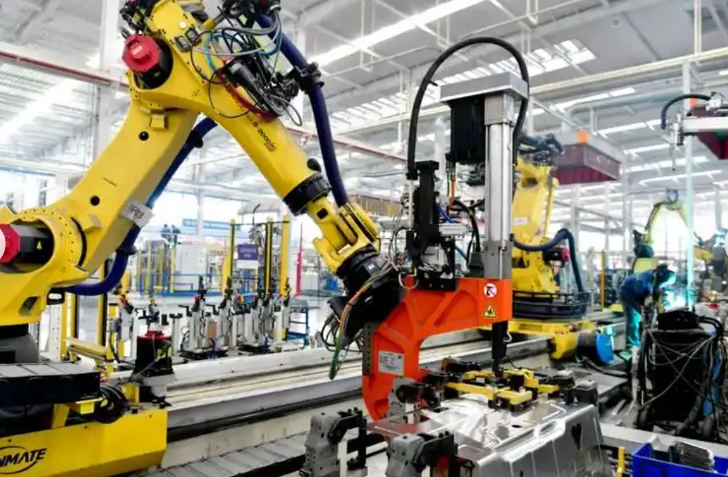
The Value I See in Embedding Industrial Robots in Mechanical Courses
When I argue for this integration in front of colleagues, I do not begin with technology. I begin with the labour market that our students are about to enter. Manufacturing has moved through a long period of mechanisation, then automation, and is now entering a phase in which flexibility matters as much as volume. Industrial robots sit at the centre of that phase because they combine repeatability with re-programmability. A dedicated cam-driven machine can produce one part very fast, but it cannot be re-tasked on Friday afternoon. An industrial robot can be re-taught, and that is precisely the property that modern batch production, mass customisation, and mixed-model assembly lines require. When I explain to a student why a robot is standing where a worker used to stand, I frame it in exactly those terms: the robot is not simply cheaper, it is more adaptable.
The consequences for the mechanical trades are concrete. In the plants that host our internships, the maintenance technician who once only aligned couplings and replaced gearboxes is now asked to check the zero position of an industrial robot, verify the tool centre point, inspect a cable dress pack, and confirm that the safety fence interlock still stops the cell. The machine operator who once only changed tools is now asked to step the robot through a taught path and confirm that the gripper jaws are seating correctly. None of these tasks requires a robotics degree, but all of them require a mechanical worker who is not intimidated by industrial robots. That is the employment gap I am trying to close.
There is a second value that is less often discussed. Teaching industrial robots inside a mechanical course improves the teaching of mechanics itself. When I explain a harmonic drive, the abstract appeal of a high reduction ratio in a compact envelope suddenly becomes visible in a robot wrist. When I explain a four-bar linkage, the parallel-link palletiser in the corner of the workshop makes the coupler curve tangible. When I explain backlash, the students can feel it in a robot joint that has lost preload and watch the resulting path error appear on the teach pendant. Industrial robots provide my mechanical theory with a vivid, modern, and unforgiving test bench, and the students learn both subjects more deeply as a result.
I summarise the value proposition in the table below, because when I present the design to a curriculum committee I need the argument to be compact and traceable.
| Dimension | What Changes in the Workshop | What the Mechanical Course Must Add | Evidence I Look For |
|---|---|---|---|
| Production organisation | Stand-alone machines give way to cells containing industrial robots | Cell-level thinking: material flow, takt time, buffers, workstation layout | Students can sketch a cell layout and justify it |
| Task content | Manual handling and simple tending are automated | Gripper design, fixture adaptation, tool centre point definition | Students can design and build a simple end effector |
| Maintenance work | Mechanical plus electromechanical plus software-adjacent | Mechanical diagnostics extended to joint, brake, belt, and cable checks on industrial robots | Students can follow a preventive maintenance checklist |
| Quality work | Repeatability and traceability become explicit requirements | Pose accuracy, repeatability, path deviation, measurement uncertainty | Students can measure and interpret path deviation |
| Safety work | Fences, interlocks, light curtains, safe stopping distances | Risk assessment applied to a mechanical system that moves on its own | Students can complete a risk assessment form |
| Career pathways | Robot tending, cell operation, integration support, maintenance | Threshold competence in programming and mechanical adaptation | Students can be placed in these roles |
Objectives and Principles That Govern My Design
Every integrated course risks becoming a survey of everything and a mastery of nothing. To prevent that, I fixed a small number of objectives before I selected any content. First, the mechanical core must remain intact: drawing interpretation, tolerance and fit, transmission of motion and power, materials and heat treatment, and basic machining must still be mastered to the same standard as before. Second, students must acquire threshold competence with industrial robots: they must be able to start up, jog, teach, run, and safely stop a robot, and they must understand what the robot is doing mechanically while it performs those actions. Third, students must be able to connect the two domains, which in practice means designing a gripper that fits a part, defining a tool centre point, and verifying that the resulting path produces an acceptable part. Fourth, the integration must be achievable with the equipment a typical technical college can actually afford and maintain.
From those objectives I derived the principles shown below. I keep this table on my desk while writing lesson plans, because it is easy to drift away from principle when a new piece of equipment arrives.
| Principle | Statement | Practical Consequence |
|---|---|---|
| Mechanical primacy | Mechanical theory is never subordinated to programming convenience | Robot topics are introduced only where they illuminate a mechanical concept |
| Spiral sequencing | The same idea returns at higher levels of difficulty | Gripping appears as a hand tool, then a fixture, then a pneumatic end effector |
| Job-role anchoring | Content exists because a real role requires it | Every module is traced to at least one verifiable task statement |
| Threshold competence | Depth is limited to what a mechanical technician genuinely needs | Kinematic modelling is taught conceptually, not as a research skill |
| Safety first | Safe behaviour is assessed before productive behaviour | A student who cannot demonstrate safe stopping does not run the cell |
| Affordability | The design must survive a constrained equipment budget | Small payload industrial robots and simulated cells are used alongside real cells |
| Measurability | Integration quality is tracked with data, not impressions | Alignment indices and competency gains are recorded each term |
The spiral sequencing principle deserves a comment because it is the mechanism by which integration avoids fragmentation. A concept such as force transmission through a joint is introduced in a purely mechanical setting, revisited when the student studies a robot joint reducer, and revisited once more when the student must decide whether a given industrial robot can carry a heavy gripper at full reach. Each pass adds a constraint, and the concept grows accordingly.
Anchoring the Design to Real Job Roles
I refuse to invent curriculum content from imagination, so my starting point is always a list of tasks drawn from the workplaces that employ our graduates. I collect these tasks through plant visits, interviews with maintenance supervisors, and structured questionnaires sent to former students who now work beside industrial robots. The task statements are then grouped into roles, and each role is mapped against the mechanical competencies and the robotics competencies it demands. The resulting matrix is the single most useful document in my design process, because it tells me what to teach, how deeply, and in what order.
| Role | Mechanical Competencies Required | Industrial Robots Competencies Required | Relative Weight |
|---|---|---|---|
| Cell operator | Part identification, fixture loading, dimensional inspection | Start-up, jogging, program selection, safe stop, fault acknowledgement | 0.20 |
| Robot tending technician | Gripper maintenance, jaw replacement, alignment of part seats | Tool centre point teaching, path touch-up, cycle observation | 0.20 |
| Mechanical maintenance technician | Bearings, belts, gearboxes, lubrication, alignment, backlash measurement | Joint inspection, brake check, zero position verification, cable dress inspection | 0.25 |
| Cell integration assistant | Fixture design, workstation layout, guarding structure | End effector design, input and output signal mapping, collaborative operation checks | 0.20 |
| Quality and measurement technician | Measurement uncertainty, gauge use, tolerance analysis | Path deviation measurement, repeatability testing, pose verification | 0.15 |
The weights in the final column are not arbitrary. I derived them by asking employers to distribute one hundred points across the five roles according to how many entry-level openings they expect in the next three years. The weights then drive the allocation of teaching hours, so the curriculum follows demand rather than tradition. If I denote the weight of role i by $$w_i$$ and the demonstrated competence of a student in that role by $$s_i$$ measured on a zero-to-one scale, then a single composite readiness index can be computed as
$$ R = \sum_{i=1}^{n} w_i \, s_i, \qquad \sum_{i=1}^{n} w_i = 1 $$
For the five roles above, a student who scores 0.9, 0.8, 0.7, 0.6, and 0.8 respectively obtains
$$ R = 0.20(0.9) + 0.20(0.8) + 0.25(0.7) + 0.20(0.6) + 0.15(0.8) = 0.755 $$
I report this index to the teaching team each term. It is a coarse instrument, but it is far better than the vague statement that a cohort “seems ready”, and it makes the effect of a curriculum change visible within a single semester.
Reconstructing the Knowledge System Around Industrial Robots
The hardest part of the design is not adding new content but re-linking old content. Traditional mechanical courses are organised by machine element or by process, and industrial robots are usually taught as a separate subject with its own logic. When the two are placed side by side, students experience them as two disconnected bodies of knowledge, and the transfer that I care about never happens. My solution is to identify the natural meeting points between the two domains and rebuild the teaching sequence around those meeting points.
The first meeting point is the joint. A mechanical student already studies bearings, shafts, keys, splines, and reducers. An industrial robot joint contains precisely these elements, but with constraints that are unfamiliar: extremely high reduction in a very small envelope, near-zero backlash, high torsional stiffness, low inertia, and a duty cycle measured in millions of reversals. When I teach planetary and harmonic reducers in the mechanical unit, I use the joint of an industrial robot as the design case. The harmonic drive reduction ratio, for a wave generator input with the flexspline fixed and the circular spline as output, is well approximated by
$$ \Delta Z = Z_{c} – Z_{f} = 2, \qquad i = \frac{Z_{f}}{Z_{c} – Z_{f}} = \frac{Z_{f}}{2} $$
so a flexspline with two hundred teeth yields a reduction of one hundred to one in a package no larger than a human fist. Students who calculate this number and then hold the actual component in their hands never forget the concept. The comparison with a conventional spur gear train is equally instructive, and I present it as a table.
| Property | Spur Gear Pair | Planetary Gear Set | Harmonic Drive |
|---|---|---|---|
| Typical single-stage ratio | 2 to 6 | 3 to 10 | 50 to 160 |
| Backlash | Moderate to large | Small | Near zero |
| Torsional stiffness | High | High | Moderate to high |
| Mass for equal torque | High | Medium | Low |
| Typical use with industrial robots | Rare in joints | Common in heavy joints | Common in wrist and small joints |
| Teaching emphasis | Fundamental geometry | Load sharing and carrier design | Elastic deformation and tooth engagement |
The second meeting point is the structure. A mechanical student knows stiffness, deflection, and the difference between a cantilever and a simply supported beam. An industrial robot arm is a cantilever whose deflection changes with configuration, and its positioning error at the tool is amplified by reach. The static deflection at the tool centre point under a payload can be estimated from a simple beam model,
$$ \delta = \frac{F L^{3}}{3 E I} $$
where $$F$$ is the load at the tool, $$L$$ is the effective reach, $$E$$ is the elastic modulus of the arm material, and $$I$$ is the second moment of area of the arm section. I ask students to compute this value for a small industrial robot and compare it with the repeatability specification in the datasheet. The comparison generates a productive confusion: repeatability is often an order of magnitude smaller than static deflection, which forces the class to distinguish between repeatability and accuracy and to understand why industrial robots are excellent at returning to a taught point and comparatively poor at absolute positioning without calibration. This distinction is one of the most valuable conceptual gifts the integration can give a mechanical student.
The third meeting point is the transmission of motion from the actuator to the workpiece. Mechanical students study linkages, cams, belts, and screw drives. Industrial robots add parallel linkages, cable dress packs, and the impedance of a joint controlled by a servo loop. A parallel-link palletiser with three actuators and a passive linkage is an ideal teaching object because its degrees of freedom can be counted directly. Using the Grübler criterion,
$$ F = \lambda (n – j – 1) + \sum_{k=1}^{j} f_{k} $$
with $$\lambda = 6$$ for a general spatial mechanism, $$n$$ links, $$j$$ joints, and $$f_k$$ the freedom of each joint, students can verify the mobility of a manipulator arm before they ever touch the controller. Counting mobility on paper and then confirming it by jogging the real machine is exactly the kind of theory-practice loop I want.
The fourth meeting point is the end effector. This is where mechanical design and robotics meet most directly, and it is where I place the greatest emphasis because it is also where employers place the greatest emphasis. A gripper is a mechanism, its jaws are levers, its stroke is limited by geometry, its gripping force is set by a pneumatic regulator, and its repeatability depends on the fits between the jaws and the part. The relationship between the pneumatic driving force and the gripping force of a simple two-jaw parallel gripper can be expressed as
$$ F_{grip} = \frac{p \, A_{p} \, \eta \, L_{1}}{L_{2}} $$
where $$p$$ is the supply pressure, $$A_p$$ the effective piston area, $$\eta$$ the mechanical efficiency, and $$L_1$$ and $$L_2$$ the lever arms of the jaw linkage. Students derive the expression, select a cylinder, build the gripper, mount it on an industrial robot, and then test whether the workpiece slips during acceleration. When it slips, the linear acceleration limit is estimated from the required friction condition,
$$ m \, a_{max} \le \mu \, F_{grip} $$
and the class rediscovers friction coefficient selection in a context where the consequence is obvious. I have found no better way to make a mechanical student care about the difference between static and dynamic friction.
The fifth meeting point is the trajectory. A mechanical student studies surface finish and cutting parameters. An industrial robot must follow a path in space, and the path is produced by coordinated motion of several joints. The forward kinematic relation from joint variables to the tool pose is written as a chain of homogeneous transformations,
$$ \mathbf{T}_{0}^{n} = \prod_{i=1}^{n} \mathbf{A}_{i}(\theta_{i}, d_{i}, a_{i}, \alpha_{i}) $$
and the relationship between joint rates and tool velocity is given by the Jacobian,
$$ \dot{\mathbf{x}} = \mathbf{J}(\mathbf{q}) \, \dot{\mathbf{q}} $$
I do not ask mechanical students to derive closed-form inverse kinematics for a six-axis industrial robot. I do ask them to understand that near certain configurations the Jacobian becomes ill-conditioned, that joint speeds must rise sharply to maintain tool speed, and that the mechanical consequence is vibration, overshoot, and wear. The determinant of the Jacobian is a convenient indicator of proximity to such a configuration,
$$ \det \mathbf{J}(\mathbf{q}) \rightarrow 0 $$
and I show the class a robot passing near a wrist singularity, where the tool speed visibly falters while the wrist joint races. From that moment, “singularity” is a mechanical phenomenon for them rather than a software message.
The full mapping between the mechanical syllabus and the integrated syllabus is given below. This table is the backbone of the reconstruction.
| Mechanical Topic | Integrated Extension | Industrial Robots Element | Practical Task | Hours |
|---|---|---|---|---|
| Drawing interpretation and tolerancing | Datum selection for fixturing and tool frames | Tool centre point definition | Define and verify a tool frame from a drawing | 8 |
| Bearings, shafts, fits | Joint construction, preload, backlash measurement | Robot joint assembly and inspection | Measure backlash and decide on adjustment | 10 |
| Gear trains and reducers | Planetary and harmonic reducers | Joint reducers of industrial robots | Compute ratio and compare with measured output | 10 |
| Strength and stiffness | Cantilever deflection under payload | Arm deflection and payload rating | Measure deflection and compare with prediction | 8 |
| Mechanisms and mobility | Degrees of freedom counting | Manipulator structures and parallel links | Verify mobility by jogging each axis | 6 |
| Pneumatics and actuation | Gripper force and stroke design | End effectors for industrial robots | Design, build, and test a two-jaw gripper | 14 |
| Machining parameters and surface quality | Path speed, acceleration, and process quality | Trajectory execution and blending | Produce a part with and without path blending | 10 |
| Measurement and inspection | Repeatability and accuracy testing | Pose verification of industrial robots | Run a repeatability test and report the result | 8 |
| Safety and risk | Risk assessment for powered motion | Guarding, interlocks, safe stop | Complete a cell risk assessment | 6 |
The hour allocations total eighty hours, which I distribute across two semesters rather than compressing into a single block. Spacing the exposure allows the mechanical concepts to settle before the robot application is introduced, and it allows the workshop to be shared with other classes without disruption.
Project-Driven Teaching and Theory-Practice Integration
Lecturing about industrial robots to a group of students who chose a hands-on trade is a waste of everyone’s time. My default method is therefore project-driven instruction, in which a real workshop task defines the need for knowledge rather than the other way round. The project provides the frame; the theory is pulled in when the project demands it; and the assessment is based on the delivered artefact and the evidence of reasoning behind it.
I select projects according to four criteria: they must be recognisable as real production tasks, they must require both mechanical design and robot programming, they must be feasible within the available workshop time, and they must be safe for students to run. A further constraint is cost. Every project must be completed with consumables that cost less than a fixed budget per student group, because a design that depends on expensive proprietary components will not survive its second year.
| Project | Mechanical Content | Industrial Robots Content | Deliverables | Duration |
|---|---|---|---|---|
| Machine tending for a small prismatic part | Fixture design, datum selection, jaw geometry | Start-up, jog, taught path, tool frame, safe stop | Fixture drawing, gripper, taught program, cycle record | 4 weeks |
| Palletising with mixed part sizes | Layer pattern design, centre of gravity reasoning | Work object frames, offset instructions, program structure | Pallet pattern sheet, running cell, cycle time report | 3 weeks |
| Deburring along a defined contour | Contact force, compliance, tool wear | Path teaching, speed control, path blending | Tool holder design, finished parts, surface assessment | 4 weeks |
| Assembly with press fit | Interference calculation, insertion chamfer | Force-limited motion, search strategy, error recovery | Fit calculation, assembled units, defect log | 4 weeks |
| Quality inspection station | Gauge selection, measurement uncertainty | Pick and place of inspected parts, signal handshake | Inspection plan, measurement data, capability index | 3 weeks |
| Preventive maintenance of a cell | Lubrication, belt tension, alignment, backlash | Zero position check, brake test, cable dress inspection | Maintenance checklist, findings report, corrective actions | 2 weeks |
A project begins with a short brief written in the language of production rather than the language of schooling. For the machine tending project, the brief states the part, the required output, the available equipment, and the acceptance conditions. It does not state which instructions to use or which fixture to build. The students must determine that themselves, and this is where the learning occurs.
I divide each project into sub-tasks and assign them to small groups. The sub-tasks are deliberately interdependent, so that a group cannot finish without communicating with the others. For the machine tending project, one group owns the fixture, one owns the gripper, one owns the taught path, and one owns the safety verification. At the weekly review, each group reports its status against the acceptance conditions, and interface problems surface early. The interface between the gripper and the fixture is almost always the source of the first serious difficulty, and resolving it teaches more about tolerancing than any lecture I could deliver.
Cycle time is the natural quantitative backbone of these projects. The cycle time of a cell containing industrial robots can be decomposed as
$$ T_{cycle} = T_{load} + T_{move} + T_{process} + T_{unload} + T_{wait} $$
and the takt time that the cell must meet is
$$ T_{takt} = \frac{T_{available}}{D_{demand}} $$
where $$T_{available}$$ is the productive time available in the period and $$D_{demand}$$ is the quantity demanded. The requirement that $$T_{cycle} \le T_{takt}$$ forces students to confront the fact that mechanical design decisions have time consequences. A heavier gripper increases $$T_{move}$$ because acceleration must be reduced. A poorly positioned fixture increases $$T_{load}$$ because the operator or the robot must travel further. A deburring tool that requires a slow feed increases $$T_{process}$$. When the inequality is violated, the class must decide what to change, and that decision is the intellectual heart of the project.
Practise time is also where the abstract idea of a tool frame becomes real. I insist that students verify a tool frame by touching the tool tip to a fixed reference point from at least four different orientations, a procedure that reveals any error in the frame definition immediately. The residual deviation between the touch points gives an estimate of the combined error of the frame definition and the mechanical compliance of the tool,
$$ \varepsilon = \max_{i,j} \left\| \mathbf{p}_{i} – \mathbf{p}_{j} \right\| $$
and I ask students to reduce this value below a stated threshold before proceeding. The threshold is chosen so that the required part tolerance can still be met, which links the measurement back to the drawing and closes the loop between design and verification.
Layered Instruction Matched to Student Baselines
The students who arrive in my workshop are not a homogeneous group. Some have grown up repairing machinery at home and can diagnose a slipping belt by sound. Others have never held a spanner. Some have programmed a small educational robot, others have never written a line of code. If I teach to the middle, I lose both ends. I therefore design each integrated module in three layers, and students are placed in a layer according to a diagnostic assessment that combines a mechanical reasoning test, a spatial ability test, and a short practical task.
| Layer | Entry Profile | Mechanical Focus | Industrial Robots Focus | Assessment Standard |
|---|---|---|---|---|
| Foundation | Weak mechanical background, no robot exposure | Identification of components, correct tool use, basic fits | Safe start-up and stop, jogging, single-point teaching | Safe and correct operation with supervision |
| Development | Sound mechanical basics, limited programming | Fixture and gripper design with guidance | Program structuring, offsets, frame definition, error recovery | Independent task completion within cycle time |
| Extension | Strong mechanical reasoning, some programming | Design under conflicting constraints, tolerance stack analysis | Cell layout, multi-unit coordination, cycle optimisation | Optimised solution with documented justification |
The layering is not a tracking system. A student may be in the development layer for gripper design and in the foundation layer for programming, and movement between layers is expected. I use a simple rule for progression. Let $$c$$ denote the demonstrated competence in a module, measured on a zero-to-one scale, and let $$\tau_{up}$$ and $$\tau_{down}$$ be the upward and downward thresholds. A student is moved up when two consecutive assessments exceed $$\tau_{up}$$ and moved down when a single assessment falls below $$\tau_{down}$$, subject to a review conversation. In practice I set
$$ \tau_{up} = 0.80, \qquad \tau_{down} = 0.50 $$
and the thresholds are recorded in the module guide so that students know exactly what is expected. Transparency of this kind removes most of the resentment that differentiated instruction can otherwise provoke.
Each layer uses the same project, which is essential for maintaining a shared class culture, but the acceptance conditions differ. In the machine tending project, foundation students must demonstrate safe start-up, correct jogging, and the teaching of three points. Development students must deliver a complete cycle with a defined tool frame and a fixture that locates the part within tolerance. Extension students must additionally reduce the cycle time by at least fifteen per cent against the baseline and justify the changes with measurement. The same workshop, the same industrial robots, and the same project therefore produce three genuinely different levels of challenge.
I also use layer-specific scaffolding in the form of checklists. Foundation students receive a start-up checklist with every step written out; development students receive a checklist with the steps named but not described; extension students receive only the acceptance conditions. Fading the scaffold is itself a teaching method, and it prepares students for the workplace, where no checklist will be handed to them.
Assessment Strategy and Evidence
Assessment in an integrated course must measure three things at once: mechanical competence, competence with industrial robots, and the ability to combine them. I use a weighted scheme with explicit components, and I publish the weights at the start of the module so that students can allocate their effort rationally. If the components are denoted $$A_1, A_2, \dots, A_m$$ with weights $$b_1, b_2, \dots, b_m$$, the final grade is
$$ G = \sum_{k=1}^{m} b_{k} A_{k}, \qquad \sum_{k=1}^{m} b_{k} = 1 $$
The components and weights I currently use are shown below.
| Component | What It Measures | Method | Weight |
|---|---|---|---|
| Mechanical knowledge test | Drawing, fits, transmission, strength | Written and calculation paper | 0.15 |
| Safety verification | Risk awareness and safe practice | Observed checklist plus oral questioning | 0.10 |
| Design portfolio | Fixture and gripper design quality | Drawings, calculations, decision log | 0.20 |
| Programming and operation | Teaching, frames, program structure, recovery | Practical task under observation | 0.20 |
| Project outcome | Function, cycle time, part quality | Measured performance against acceptance conditions | 0.20 |
| Reflective report | Reasoning, diagnosis, learning | Written analysis of deviations and corrective actions | 0.15 |
The safety component is deliberately separate and carries a gate condition. A student whose observed safety performance falls below the threshold cannot proceed to the running of the cell regardless of the total grade, and the rule is
$$ G_{final} = G \quad \text{if} \quad A_{safety} \ge 0.70, \qquad G_{final} = \text{unsatisfactory otherwise} $$
This is not a punitive device. It reflects the reality that an unsafe technician is not employable in a cell containing industrial robots, no matter how skilled, and the students accept the rule once it is explained in those terms.
I am also careful to assess the diagnosis of failure, not only the production of success. Every project is required to include at least one deliberately induced fault, such as an incorrectly defined tool frame, a loose gripper jaw, or a degraded approach speed. Students must detect the fault, explain its mechanical cause, and correct it. The ability to move from a symptom to a root cause is the most transferable skill I can give a maintenance-oriented student, and it is directly exercised by industrial robots because their failures are usually mechanical at the root and programmable at the surface.
To check that my assessment is internally consistent, I compute a reliability coefficient for the rubric-based components each term. For $$k$$ rubric criteria with item variances $$\sigma_{i}^{2}$$ and total variance $$\sigma_{t}^{2}$$, Cronbach’s coefficient is
$$ \alpha = \frac{k}{k-1} \left( 1 – \frac{\sum_{i=1}^{k} \sigma_{i}^{2}}{\sigma_{t}^{2}} \right) $$
Values below about 0.70 prompt me to rewrite the rubric descriptors, because a rubric that cannot distinguish students reliably is not measuring anything useful. This practice has improved the consistency of my grading considerably and has made moderation conversations with colleagues much more productive.
Workshop Conditions, Safety, and Cost
A good design that cannot be resourced is not a design. I therefore work within a realistic inventory and use simulation where hardware is unavailable. Simulation is not a compromise I apologise for. Offline programming environments allow students to build a cell, define frames, generate paths, and detect collisions long before they touch a real machine, and the transfer from simulation to the real industrial robots in my workshop is rapid because the concepts are identical. The combination of a small number of real cells and a larger number of simulated cells gives every student meaningful practice time.
| Resource | Minimum Quantity | Primary Use | Alternative if Unavailable |
|---|---|---|---|
| Small payload industrial robots with controller | 2 units | Real programming, teaching, cycle work | Borrowed unit from a partner enterprise |
| Quick-change end effector interface | 2 sets | Gripper swapping and tool frame teaching | Manually bolted interface |
| Pneumatic supply with regulator and valve island | 1 station | Gripper actuation and force control | Electric gripper with adjustable force |
| Machining centre or lathe | 1 unit | Tending target and process cycle | Simplified process station with simulated cycle |
| Safety fence with interlocked gate | 2 cells | Mandatory separation of students from motion | Light curtain with monitored reset |
| Teaching pendants, one per robot | 2 units | Teaching, jogging, diagnostics | Simulation pendant |
| Offline programming licences | 1 per two students | Cell layout and path planning | Free educational simulation environment |
| Measurement equipment | 1 set per group | Repeatability, deflection, and fit verification | Dial indicators and gauge blocks |
Safety is designed into the layout rather than added afterwards. The minimum safe distance between the limit of the robot envelope and the fence is determined from the stopping performance of the machine,
$$ S = K (T_{r} + T_{s}) + C + Z_{d} + Z_{r} $$
where $$K$$ is the approach speed constant, $$T_r$$ is the response time of the detection device, $$T_s$$ is the stopping time of the machine, $$C$$ is a penetration factor, and the two terms $$Z_d$$ and $$Z_r$$ account for measurement uncertainty and the position of the hazard relative to the fence. I make students apply this relation themselves during the layout project, because the formula converts the fence from an arbitrary boundary into a calculated requirement. The pedagogical effect is strong: students who have computed a safety distance treat the fence with a respect that no amount of lecturing produces.
Beyond the fence, I teach three layers of protection. The first is mechanical separation, which prevents reach-through. The second is interlocking, which removes power when the gate opens or a light curtain is broken. The third is procedural, covering work inside the cell, lockout and tagout, and the rules for entering a cell containing industrial robots while the controller is energised. Procedural safety is the layer most often forgotten in training, and it is the layer most often responsible for real incidents, so I assess it explicitly.
Cost must be considered honestly. The economic case for a cell containing industrial robots is evaluated with a total cost of ownership model. If the investment is $$C_0$$, the annual operating cost is $$C_{op}$$, and the annual saving from labour, scrap reduction, and quality improvement is $$S_{a}$$ over a service life of $$N$$ years with a discount rate $$r$$, the net present value is
$$ NPV = -C_{0} + \sum_{t=1}^{N} \frac{S_{a} – C_{op}}{(1+r)^{t}} $$
and the payback period, for constant annual net savings, is
$$ T_{payback} = \frac{C_{0}}{S_{a} – C_{op}} $$
I include this calculation in the extension layer because it forces students to see industrial robots as an investment rather than a gadget. It also produces a useful side effect: students begin to propose design changes that reduce cost, such as using a simple two-position pneumatic gripper instead of a servo-electric one, and to justify those choices with numbers. Designing to a cost constraint is part of mechanical competence, and it belongs in the course.
Teacher Capability and Cooperation with Enterprises
None of this works if the teacher is not confident with industrial robots. My own path was to spend structured time in a partner plant, working alongside maintenance technicians on real equipment, and then to translate that experience into teaching materials. I now treat teacher development as a permanent activity with its own plan, because a course that integrates industrial robots degrades quickly if the teaching team’s knowledge does not keep pace with the equipment.
| Development Activity | Frequency | Expected Outcome | Evidence Collected |
|---|---|---|---|
| Enterprise attachment in a maintenance team | Two weeks per year | Current practice, real fault cases | Case notes, photographs, fault log |
| Manufacturer training on installed industrial robots | Once per equipment generation | Correct use of teach pendant and diagnostics | Certificate, teaching demonstration |
| Internal peer teaching sessions | Monthly | Shared lesson materials and rubrics | Lesson plans, peer observation notes |
| Joint project design with employers | Twice per year | Projects aligned with production needs | Signed project briefs, acceptance conditions |
| Reflective review of assessment data | Each term | Targeted revision of weak modules | Score distributions, reliability coefficients |
Cooperation with enterprises extends beyond teacher training. The most valuable contribution employers make is not equipment donation but task authenticity. When a maintenance supervisor describes the exact sequence used to replace a gripper jaw on a production line, that sequence becomes a teaching asset. When a production engineer explains why a particular approach speed was reduced after a part was scratched, that explanation becomes a case study. I collect these accounts systematically and build them into the project briefs, which is why the briefs read like production documents rather than textbook exercises.
There is a reciprocal benefit that I did not anticipate. Partner enterprises have begun to use our workshop for short internal courses, because the layered teaching material is well suited to mixed-ability groups of adult technicians. In return, they provide access, spare components, and advice at no cost to the college. The relationship has become genuinely mutual rather than a one-way request for support.
Quality Assurance and Continuous Improvement
I treat the integrated curriculum as a system that must be measured and corrected, not as a document that is written once and filed. Every term I collect a small set of indicators and review them with the teaching team. The indicators are chosen so that they can be collected without extra administration, and each one is tied to a specific decision.
| Indicator | Definition | Target | Decision Triggered |
|---|---|---|---|
| Competency gain | Mean difference between pre and post assessment | $$\ge 0.25$$ | Revise modules with low gain |
| Curriculum alignment index | Proportion of taught modules traced to a verified task statement | $$\ge 0.90$$ | Retire untraceable content |
| Cycle time attainment | Proportion of project groups meeting the takt requirement | $$\ge 0.70$$ | Adjust project difficulty or equipment |
| Safety incident rate | Recordable near-misses and incidents per thousand student-hours | $$0$$ | Immediate layout or procedure review |
| Placement in robot-related roles | Proportion of graduates entering such roles within six months | $$\ge 0.40$$ | Adjust role weights and content depth |
| Rubric reliability | Cronbach coefficient for rubric components | $$\ge 0.70$$ | Rewrite rubric descriptors |
The competency gain is the simplest and most informative of these. If $$C_{pre}$$ and $$C_{post}$$ are the mean composite competencies before and after the module, the gain is
$$ \Delta C = C_{post} – C_{pre} $$
and I disaggregate it by layer to make sure that the foundation group is not being left behind while the extension group races ahead. An integrated course that raises the average while widening the gap between strongest and weakest has failed one of its main purposes, and only disaggregated data reveals that failure.
The curriculum alignment index is computed as the proportion of taught modules that can be traced to at least one verified task statement,
$$ A = \frac{1}{N} \sum_{j=1}^{N} c_{j}, \qquad c_{j} \in \{0, 1\} $$
where $$N$$ is the number of modules and $$c_j$$ indicates whether module $$j$$ is traceable. Content that cannot be traced is a candidate for removal. This rule sounds harsh, but in my experience it removes very little and clarifies a great deal, because it forces every module to justify its existence in the language of employment rather than the language of tradition.
I also monitor the learning curve of students on repetitive tasks, because the speed with which a student becomes productive on a cell containing industrial robots is a practical indicator of readiness. If the first repetition of a task takes $$T_1$$ and the learning rate is $$b$$, then the time for the $$n$$-th repetition is approximated by
$$ T_{n} = T_{1} \, n^{\log_{2} b} $$
Students whose times fail to follow a plausible curve usually lack a systematic method rather than dexterity, and that diagnosis changes what I teach them next.
Risks and How I Mitigate Them
Any curriculum change carries risks, and I prefer to state them openly rather than discover them in the third term. The table below lists the risks I have identified and the mitigations I apply.
| Risk | Description | Mitigation |
|---|---|---|
| Loss of mechanical depth | Robot content crowds out core mechanical theory | Fixed floor of mechanical hours; module tracing to task statements |
| Superficial coverage | Students touch many topics and master none | Threshold competence definition; depth limits stated in the module guide |
| Equipment shortage | Too few industrial robots for the class size | Simulation plus rotating real-machine time; scheduled cell access |
| Safety exposure | Students near powered motion | Layered protection, safety gate condition in assessment, small payload machines |
| Teacher overload | Preparation time exceeds available hours | Shared project bank, reusable briefs, peer teaching sessions |
| Employer mismatch | Taught content drifts from actual practice | Annual task verification with partner enterprises |
| Student discouragement | Foundation layer students feel left behind | Same project with different acceptance conditions; transparent progression rules |
The risk I take most seriously is the first one. It is easy for an integrated course to drift until it becomes a robotics course with mechanical illustrations, and the graduates of such a course are less employable in mechanical maintenance than they were before. The safeguard is the mechanical hour floor and the tracing rule, both of which are auditable. I would rather defend a slightly conservative balance than attempt an ambitious one that quietly erodes the mechanical foundation.
What I Have Learned and What Comes Next
Looking back at the terms in which I have run this design, several lessons stand out. The first is that the strongest learning moments occur at the interfaces, not inside the disciplines. When a student discovers that a gripper which works perfectly in a static test slips during rapid handling, the lesson about friction, acceleration, and gripping force lands with unusual force, because the failure is visible and the remedy requires calculation. When a student finds that a robot cannot reach a point at full extension without exceeding a deflection limit, the lesson about stiffness becomes personal. Industrial robots are valuable in a mechanical course precisely because they make mechanical consequences visible and immediate.
The second lesson is that operational safety must be taught as engineering, not as compliance. The moment students compute a stopping distance themselves, the fence stops being an obstacle and becomes a design output. In my experience this shift in attitude is more durable than any set of rules, and it transfers to every powered machine the student will ever work with.
The third lesson is that integration is a maintenance task. Every new model of industrial robots introduced into the workshop changes the frames, the instructions, the diagnostics, and sometimes the safety architecture. A curriculum that integrated industrial robots three years ago and has not been revised since is already drifting away from practice. For that reason I have made the review cycle permanent rather than periodic, and I keep the task statements, the project briefs, and the rubrics in a single controlled document that any member of the teaching team can update.
My next steps are focused rather than ambitious. I intend to strengthen the measurement of path accuracy so that students can separate the contribution of the mechanical system from the contribution of the control system. I intend to build two additional project briefs around collaborative operation, where mechanical compliance and force limits matter more than speed. I intend to extend the layer structure so that extension students can attempt a small cell layout for a real industrial robots application proposed by a partner enterprise, with the layout reviewed by the enterprise engineer. And I intend to keep tracking the composite readiness index and the competency gain each term, because the numbers are what keep the design honest.
Conclusion
Integrating industrial robots into a mechanical curriculum is not a matter of adding a new subject to an already crowded timetable. It is a matter of recognising that the mechanical workshop has changed, and of re-linking mechanical theory to the machines that now stand in it. My approach rests on a small number of commitments: keep the mechanical core intact, anchor content to verified job roles, reconstruct the knowledge system around genuine meeting points such as joints, structures, end effectors, and trajectories, teach through projects with measurable acceptance conditions, differentiate instruction so that every student progresses, assess safety and diagnosis as seriously as production, and review the whole system with data every term. When these commitments are honoured, students leave the workshop able to read a drawing, design a fixture, build a gripper, teach a path, verify a frame, measure a deviation, and explain why any of it matters. They also leave able to work confidently alongside industrial robots, which is what the employers who host them now expect. The design is neither finished nor perfect, but it is measurable, revisable, and grounded in the work that my students will actually do, and that is the standard I hold it to.