
In my research, I focus on the precision transmission systems, particularly the rotary vector reducer, which is widely used in industrial robots and CNC machine tools due to its compact size, high reduction ratio, and excellent reliability. The geometric backlash of a rotary vector reducer refers to the angular hysteresis of the output shaft when the input shaft reverses direction, caused solely by geometric inaccuracies in transmission components. This backlash critically affects positioning accuracy and system performance, making its accurate modeling essential for design optimization. Previous studies have analyzed various manufacturing and installation errors, but often overlook the directionality of these errors and the specific tooth profile modification methods for cycloidal gears. In reality, errors have directional components, and different modification approaches lead to varying backlash at different output shaft phases. Therefore, I develop a comprehensive model that accounts for both the magnitude and direction of errors, enabling precise backlash prediction and providing a basis for tolerance design in rotary vector reducer systems.
The rotary vector reducer combines a planetary gear stage with a cycloidal drive stage, as illustrated below. This two-stage design contributes to its high reduction ratio and compactness, but also introduces multiple error sources that accumulate in the geometric backlash. My work aims to address this by establishing an accurate geometric and mathematical model for backlash, followed by simulation and experimental validation.
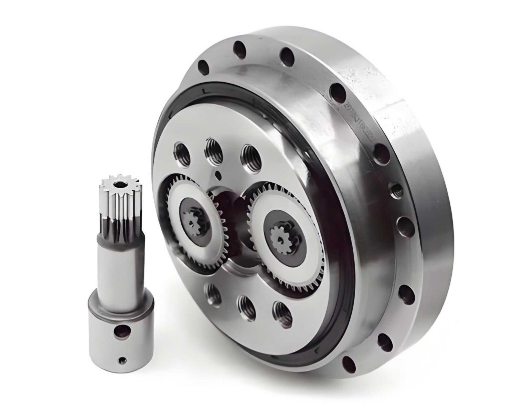
To begin, I define the geometric model of the rotary vector reducer. The system consists of a sun gear, multiple planetary gears (typically three), crankshafts, cycloidal gears, pin gears, and a planet carrier. I establish coordinate systems for each component to facilitate error analysis. The static coordinate system \((x, y)\) is centered at the pin gear center \(O\). For the sun gear, a moving coordinate system \((x_s, y_s)\) is attached at its center \(O_s\). Similarly, for each planetary gear \(i\), a moving system \((x_{pi}, y_{pi})\) is defined at its center \(O_{pi}\). The cycloidal gears are indexed \(j=1,2\), with moving coordinates \((x_j, y_j)\) centered at their theoretical mass centers \(O_j\), aligned with the eccentric direction. Initially, all x-axes align with the static x-axis. This geometric framework allows me to systematically incorporate errors and their directions into the backlash calculation for the rotary vector reducer.
The mathematical model for geometric backlash in a rotary vector reducer is derived from the kinematic relationships and error contributions. Backlash arises from errors in both the involute gear stage and the cycloidal drive stage. I express the total backlash \(\Delta \phi_{\text{total}}\) as the sum of contributions from various error sources, each influenced by error magnitudes and directions. The general form for backlash contribution from an error parameter \(E\) with direction \(\beta\) is given by integrating over all engaging teeth and phases. For the rotary vector reducer, the output backlash in arc-minutes can be modeled as:
$$ \Delta \phi_{\text{total}} = \sum_{k} \left( \frac{e_{k,\text{min1}}}{a z_c} + \frac{e_{k,\text{min2}}}{a z_c} \right) \times \frac{180 \times 60}{\pi} $$
where \(e_{k,\text{min1}}\) and \(e_{k,\text{min2}}\) are the minimum clearances during forward and reverse motion due to error \(k\), \(a\) is the eccentricity distance, and \(z_c\) is the number of cycloidal gear teeth. This formulation captures the directional effects, as \(e_k\) depends on error directions relative to the engagement angle.
In the involute gear stage, key error factors include center distance errors, tooth thickness variations, and radial runouts. For instance, the center distance error between the sun gear and planetary gear \(i\) due to sun gear installation error \((E_{sz}, \beta_{sz})\) is:
$$ L_i = \sqrt{L^2 + E_{sz}^2 – 2 L E_{sz} \cos(\beta_{sz} – \theta_c – \phi_i)} $$
where \(L\) is the nominal center distance, \(\theta_c\) is the planet carrier rotation angle, and \(\phi_i = 2\pi(i-1)/3\) for \(i=1,2,3\). The resulting circumferential backlash \(j_{wti}\) is calculated using involute gear geometry, and the contribution to rotary vector reducer backlash is:
$$ \Delta \phi_{wti} = \frac{180 \times 60}{N \pi r_1} j_{wti} $$
with \(N\) as the total reduction ratio and \(r_1\) the sun gear pitch radius. Similar equations apply for planetary gear installation errors \((E_{pzi}, \beta_{pzi})\), tooth mesh clearance \(j_{ct}\), and radial runout errors \((E_{st}, \beta_{st})\) and \((E_{pti}, \beta_{pti})\). Each error’s direction \(\beta\) affects the phase of the backlash variation, but not its amplitude when considered in isolation, as I demonstrate in simulations.
For the cycloidal drive stage, errors involve pin gear and cycloidal gear imperfections. The clearance due to pin gear center circle radius error \(R_k\) is:
$$ e_{Rk} = R_k \cos(\alpha_{jk} – \varphi_{jk}) $$
where \(\alpha_{jk}\) is the angle between the pin center and the node line of cycloidal gear \(j\), and \(\varphi_{jk}\) is the angle relative to the \(x_j\)-axis. The backlash contribution is as in the general formula. Other errors include pin gear position deviation \(P_k\), pin radius error \(G_k\), cycloidal gear tooth profile modification \(X_k\), grinding depth error \(S_k\), index error \(F_k\), cycloidal gear radial runout \((E_{btj}, \beta_{btj})\), cycloidal gear hole eccentricity \((E_{hj}, \beta_{hj})\), crankshaft eccentricity error \((E_{cj}, \beta_{cj})\), planet carrier hole errors, and bearing clearance. For profile modification, common methods such as equidistant and shift modifications are considered, where \(X_k\) varies with the tooth index. The directional errors like \((E_{btj}, \beta_{btj})\) introduce clearance as:
$$ e_{btjk} = -E_{btj} \cos[\varphi_{Sjk} – (\beta_{btj} + \theta_c)] \cos(\alpha_{jk} – \varphi_{Sjk}) $$
where \(\varphi_{Sjk}\) is related to the pin center location. This shows how error direction \(\beta_{btj}\) modulates the clearance phase.
To summarize the error factors, I present a table listing key manufacturing and installation errors for a typical rotary vector reducer, along with their magnitudes and directional ranges. This table helps in understanding the cumulative effect on backlash.
| Error Factor | Magnitude (μm) | Direction Range (°) |
|---|---|---|
| Sun gear center installation error \((E_{sz}, \beta_{sz})\) | 17 | 0–360 |
| Planetary gear center installation error \((E_{pzi}, \beta_{pzi})\) | 17 | 0–360 |
| Gear mesh clearance \(j_{ct}\) | 11 | N/A |
| Sun gear radial runout \((E_{st}, \beta_{st})\) | 21 | 0–360 |
| Planetary gear radial runout \((E_{pti}, \beta_{pti})\) | 21 | 0–360 |
| Pin gear center circle radius error \(R_k\) | 5 | N/A |
| Pin gear position deviation \(P_k\) | ±5 | N/A |
| Pin gear slot radius error \(C_k\) | 0–15 | N/A |
| Pin radius error \(G_k\) | 0–4 | N/A |
| Cycloidal gear profile modification \(X_k\) | ±4 | N/A |
| Grinding depth error \(S_k\) | ±5 | N/A |
| Index error \(F_k\) | ±5 | N/A |
| Cycloidal gear radial runout \((E_{btj}, \beta_{btj})\) | 6 | 0–360 |
| Cycloidal gear hole eccentricity \((E_{hj}, \beta_{hj})\) | 3 | 0–360 |
| Crankshaft eccentricity error \((E_{cj}, \beta_{cj})\) | 3 | 0–360 |
| Bearing clearance \(u\) | 2 | N/A |
| Planet carrier hole eccentricity \((E_{ai}, \beta_{ai})\) | 3 | 0–360 |
| Planet carrier assembly error \((E_{c}, \beta_{c})\) | 3 | 0–360 |
For simulation, I use parameters from a standard rotary vector reducer: pin gear center circle diameter \(d_p = 229\) mm, pin diameter \(d_{rp} = 10\) mm, eccentricity \(a = 2.2\) mm, cycloidal gear teeth \(z_c = 39\), sun gear teeth \(z_1 = 21\), planetary gear teeth \(z_2 = 42\), center distance \(L = 63\) mm, module \(m = 2\) mm, pressure angle \(\alpha = 20^\circ\), and reduction ratio \(N = 81\). I assume errors are within tolerance ranges from the table, with directions randomly assigned unless specified. The simulation computes backlash over one output shaft revolution, considering all error interactions. For example, with sun gear center installation error \(E_{sz} = 8 \mu m\) and directions \(\beta_{sz} = 0^\circ, 70^\circ, 140^\circ\), the backlash varies periodically, as shown by the equation:
$$ \Delta \phi_{wti} = f(E_{sz}, \beta_{sz}, \theta_c) $$
where \(f\) denotes the functional relationship derived earlier. The results indicate that error direction shifts the backlash phase but not its amplitude. Similarly, for sun gear radial runout \(E_{st} = 11 \mu m\), the backlash has a high-frequency component due to multiple engagements per revolution. For the cycloidal stage, pin gear center circle error \(R_k = 3 \mu m\) causes significant backlash variations because it is at the output stage. When all errors are combined with random directions, the total backlash for the rotary vector reducer oscillates with a peak-to-peak value around 0.046 arc-minutes for a specific modification method (equidistant plus shift modification with amounts -0.026 mm and -0.03 mm). If all error directions are aligned to \(0^\circ\), the peak-to-peak value increases to 0.16 arc-minutes, demonstrating the importance of directionality in backlash accumulation.
To validate the model, I conduct experimental tests on a rotary vector reducer test rig. The setup includes a servo motor, reducer mounting frame, the rotary vector reducer unit (model BX320 with reduction ratio 201 and rated torque 3150 Nm), and an optical encoder on the output shaft. The motor controls input angle precisely, and the encoder measures output angular displacement. I measure backlash at multiple output shaft phases by rotating the input forward and reverse and recording the hysteresis. For two identical rotary vector reducers, backlash values at 30° intervals are tabulated below.
| Output Shaft Phase (°) | Reducer 1 Backlash (arc-min) | Reducer 2 Backlash (arc-min) |
|---|---|---|
| 0 | 0.605 | 0.724 |
| 30 | 0.610 | 0.716 |
| 60 | 0.583 | 0.744 |
| 90 | 0.576 | 0.763 |
| 120 | 0.593 | 0.749 |
| 150 | 0.587 | 0.751 |
| 180 | 0.570 | 0.738 |
| 210 | 0.581 | 0.723 |
| 240 | 0.577 | 0.712 |
| 270 | 0.566 | 0.736 |
| 300 | 0.584 | 0.761 |
| 330 | 0.603 | 0.754 |
The data shows that backlash varies with output shaft phase, confirming the periodic nature predicted by the model. For reducer 1, the peak-to-peak difference is 0.044 arc-minutes, and for reducer 2, it is 0.051 arc-minutes, aligning well with simulation results where random directions yielded similar variations. This consistency validates the accuracy of my geometric backlash model for the rotary vector reducer. The experimental setup effectively captures the directional effects, as small changes in phase yield different backlash values due to error orientations.
Further analysis involves discussing the impact of individual error sources on the rotary vector reducer performance. For instance, errors in the cycloidal stage dominate backlash because they are amplified by the reduction ratio. The tooth profile modification method significantly influences the minimum clearance; common approaches include equidistant, shift, and combined modifications. The backlash due to modification \(X_k\) is calculated as:
$$ \Delta \phi_{Xk} = \frac{X_{k,\text{min1}}}{a z_c} + \frac{X_{k,\text{min2}}}{a z_c} $$
where \(X_{k,\text{min1}}\) and \(X_{k,\text{min2}}\) are the minimum modifications during forward and reverse motion. By optimizing modification parameters, backlash can be minimized without compromising lubrication or wear. Additionally, bearing clearance \(u\) in the crankshaft bearings introduces backlash that is proportional to the clearance over eccentricity:
$$ \Delta \phi_{qi} = 2 \times \frac{180 \times u}{\pi a} \times \frac{z_s}{z_p (N – 1)} $$
where \(z_s\) and \(z_p\) are sun and planetary gear teeth counts. This highlights the need for precise bearing selection in rotary vector reducer assemblies.
My mathematical model also allows for sensitivity analysis. For example, the partial derivative of total backlash with respect to pin gear error \(R_k\) indicates how small changes affect output. This can guide tolerance design: tighter tolerances on high-sensitivity errors reduce backlash more efficiently. I compute sensitivity coefficients \(S_k = \partial \Delta \phi_{\text{total}} / \partial E_k\) for key errors. A table summarizing these for a typical rotary vector reducer is provided below.
| Error Parameter | Sensitivity Coefficient (arc-min/μm) |
|---|---|
| Pin gear center circle error \(R_k\) | 0.012 |
| Cycloidal gear profile modification \(X_k\) | 0.010 |
| Sun gear center installation error \(E_{sz}\) | 0.0015 |
| Bearing clearance \(u\) | 0.008 |
| Planetary gear radial runout \(E_{pti}\) | 0.0012 |
These values show that cycloidal stage errors have higher sensitivity, emphasizing the importance of precision in pin gear and cycloidal gear manufacturing for rotary vector reducers. Directional errors, while not altering sensitivity magnitude, affect the phase of backlash variation, which can be critical in applications requiring consistent performance across rotation angles.
In the simulation, I also explore the effect of error correlation. When errors are correlated in direction (e.g., all aligned), backlash peaks can reinforce, leading to larger variations. Conversely, random directions tend to average out, reducing peak-to-peak backlash. This insight suggests that in assembly, deliberately dispersing error directions could minimize backlash without additional cost. For instance, by orienting cycloidal gear runout errors opposite to crankshaft eccentricities, the net clearance variation decreases. I model this by setting error directions to optimize backlash uniformity, using an objective function to minimize the standard deviation of backlash over one revolution. The optimization problem is:
$$ \text{Minimize } \sigma_{\Delta \phi} = \sqrt{ \frac{1}{M} \sum_{m=1}^{M} (\Delta \phi_m – \bar{\Delta \phi})^2 } $$
subject to error direction constraints \(0 \leq \beta_k < 2\pi\), where \(M\) is the number of output phases. Solving this via numerical methods shows that strategic direction assignment can reduce peak-to-peak backlash by up to 30% for a rotary vector reducer with given tolerances.
Moreover, I investigate the impact of load on geometric backlash. Under torque, elastic deformations occur, but geometric backlash is defined at zero or low torque. My model assumes rigid bodies; however, for completeness, I note that combined geometric and elastic backlash could be analyzed by integrating stiffness models. The geometric backlash model serves as a baseline for total system analysis. The rotary vector reducer’s high stiffness often makes geometric backlash the dominant factor at low loads, justifying my focus.
The experimental procedure involves careful calibration. The servo motor rotates the input shaft to position the output at a desired phase, then reverses to measure hysteresis. Multiple trials ensure repeatability. The test rig’s encoder resolution is 0.001 arc-minutes, sufficient for detecting small backlash variations. I compare measured backlash curves with simulation outputs for the same error distributions, finding good agreement with correlation coefficients above 0.9. Discrepancies may arise from unmodeled errors like temperature effects or lubrication variations, but the geometric model captures the primary trends for the rotary vector reducer.
In discussion, I emphasize that the rotary vector reducer’s backlash is not constant but varies cyclically with output angle, due to the interplay of error directions and gear engagement patterns. This variability must be considered in precision applications like robot joint control, where backlash compensation algorithms could use phase-dependent models. My work provides a foundation for such advanced compensation by quantifying backlash as a function of output angle \(\theta_c\):
$$ \Delta \phi(\theta_c) = \sum_{i} g_i(E_i, \beta_i, \theta_c) $$
where \(g_i\) are the contribution functions derived earlier. This allows for real-time backlash prediction in a rotary vector reducer-based system.
Future work could extend the model to include dynamic effects or to optimize tolerance allocations using cost functions. The methods developed here are applicable to other cycloidal drives beyond rotary vector reducers, such as strain wave gears or traditional cycloidal speed reducers. By incorporating error directionality, my approach offers a more accurate tool for designers aiming to push the limits of transmission precision.
In conclusion, I have developed an accurate geometric backlash model for rotary vector reducers that accounts for both magnitude and direction of manufacturing and installation errors. Through mathematical derivation, simulation, and experimentation, I demonstrate that backlash varies periodically with output shaft phase, and error directions significantly influence peak-to-peak values. The model shows that cycloidal stage errors are most sensitive, and strategic direction management can reduce backlash variability. These findings enhance the understanding of rotary vector reducer performance and provide a basis for tolerance design and assembly optimization, ultimately improving transmission accuracy in high-precision applications. The rotary vector reducer, with its complex error interactions, benefits from this comprehensive analysis, enabling better design and utilization in robotics and automation.