
Abstract This paper presents a novel design in robot technology, focusing on a unipedal robot integrated with magnetorheological (MR) joints to address the challenges of insufficient burst power and high energy consumption in traditional legged robots. We introduce the principles and structure of the MR joint, followed by kinematic and dynamic analyses of the robot’s jumping motion. Through COMSOL simulations and experimental validations, we demonstrate the effectiveness of the MR joint in enhancing jumping height while reducing motor current. The results highlight the potential of MR technology in improving the mobility and energy efficiency of legged robots, marking a significant advancement in robot technology.
Keywords: Robot technology; Magnetorheological joints; Variable stiffness; Jumping performance; Kinematic analysis
1. Introduction
In the realm of robot technology, legged robots have garnered significant attention due to their exceptional mobility and adaptability in complex terrains. However, existing designs face critical challenges, particularly during jumping motions: traditional electric or hydraulic actuators often struggle to deliver sufficient instantaneous power, leading to limited jump heights and inefficient energy use. This study aims to bridge this gap by integrating magnetorheological (MR) technology into robot joints, a breakthrough in robot technology that enables dynamic stiffness adjustment and energy storage.
1.1 Background and Challenges in Robot Technology
Legged robots typically rely on hydraulic or electric drives. Hydraulic systems offer high power density but suffer from bulkiness and complex control due to nonlinearity . Electric drives, while more compact, face limitations in burst performance and energy efficiency during dynamic motions like jumping. For instance, the MIT Cheetah series uses torque motors with planetary reducers, achieving high-speed control but incurring mechanical and energy losses during explosive movements .
To address these issues, researchers have explored elastic actuators, combining motors with springs to store energy. Examples include series elastic actuators (SEAs) and parallel elastic actuators (PEAs), which improve shock absorption and energy reuse . However, traditional elastic systems rely on mechanical locks or clutches, which are inflexible and inefficient in energy management .
1.2 Innovation: MR Technology in Robot Joints
Magnetorheological fluid, a key component in advanced robot technology, exhibits rapid rheological changes under magnetic fields. When a magnetic field is applied, iron particles in the fluid align to form chains, increasing shear stress and damping within milliseconds . This property enables dynamic control of joint stiffness, making MR joints ideal for energy storage and release during jumping.
In this study, we design an MR-bearing as a dynamic locking mechanism, integrated into a unipedal robot’s knee joint. By controlling the magnetic field, we achieve flexible coupling between the elastic element (a torsion spring) and the electric motor, allowing efficient energy transfer during the jumping cycle .
2. Magnetorheological Joint Design and Principles
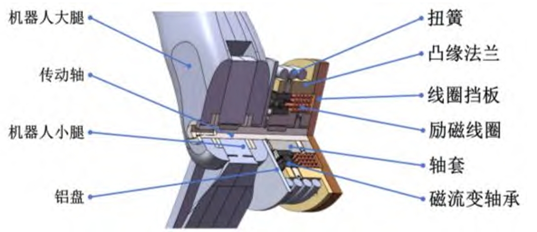
2.1 Structure of the MR Joint
The MR joint is composed of a deep-groove ball bearing filled with MR fluid (86.3% iron powder by mass) . When no magnetic field is applied, the MR fluid acts as a lubricant, allowing free rotation of the bearing . Upon energizing the coil, a magnetic circuit is established through the shaft, sleeve, bearing, and flange, causing the MR fluid to solidify and lock the bearing . This locking mechanism enables the torsion spring (placed between the aluminum plate and flange) to store energy as the joint compresses during the landing phase .
2.2 Working Principle
The damping torque of the MR bearing is influenced by the magnetic field strength, which is controlled by the coil current. As the current increases, the magnetic flux density in the bearing rises, enhancing the locking torque . This relationship is critical for adjusting the joint’s stiffness in real time, a key innovation in robot technology for dynamic motion control.
3. Kinematic and Dynamic Analysis of the Unipedal Robot
To model the robot’s jumping motion, we simplify it as a spring-loaded inverted pendulum (SLIP) with variable stiffness, incorporating the MR joint’s dynamics.
3.1 Kinematic Model
The simplified 连杆 model (linkage model) assumes the robot’s mass is concentrated at the joint motor center (质心). Using geometric relationships, we derive the kinematic equations for the virtual leg length (ξ) and ground angle (ψ):
\(\begin{cases} \xi = 2l \cdot \cos\left(\frac{\theta_{1j}}{2}\right) \\ \psi = \frac{\pi}{2} + \frac{\theta_{1j}}{2} + \theta_{2j} \end{cases}\)
where l is the length of the thigh and shank, \(\theta_{1j}\) is the knee angle, and \(\theta_{2j}\) is the hip angle .
The static force-moment relationship is established via the Jacobian matrix transpose:
\(\begin{bmatrix} F_{\xi} \\ T_{\psi} \end{bmatrix} = J^{-T} \begin{bmatrix} \tau_{1j} \\ \tau_{2j} \end{bmatrix} = \begin{bmatrix} \frac{1}{-l \cdot \sin\left(\frac{\theta_{1j}}{2}\right)} & \frac{1}{2l \cdot \sin\left(\frac{\theta_{1j}}{2}\right)} \\ 0 & 1 \end{bmatrix} \begin{bmatrix} \tau_{1j} \\ \tau_{2j} \end{bmatrix}\)
Here, \(F_{\xi}\) is the ground reaction force, \(T_{\psi}\) is the moment about the virtual leg, and \(\tau_{1j}, \tau_{2j}\) are the knee and hip torques .
3.2 Dynamic Model
During the stance phase, the robot’s dynamics are described by a virtual spring-damper system:
\(m\ddot{\xi} = -k_{\xi}(\xi – \xi_0) – b_{\xi}\dot{\xi} + mg\cos\psi\)
where \(k_{\xi}\) is the virtual spring stiffness, \(b_{\xi}\) is the damping coefficient, and \(\xi_0\) is the rest length of the virtual spring . For vertical jumping (ψ = π/2), the model simplifies to a one-dimensional system:
\(m\ddot{z} = -k_z(z – z_0) – b_z\dot{z} + mg\)
During the flight phase, the dynamics reduce to:
\(\ddot{z} = -g\)
The stiffness \(k_z\) is decomposed into a virtual component (\(k_{zv}\)) and the MR joint’s elastic component (\(k_z’\)), allowing stiffness adjustment by locking or releasing the MR joint .
4. Jumping Gait Design and Control
4.1 Gait Phases
A complete jumping cycle consists of four phases:
- Descent: Free fall from the apex to ground contact, converting gravitational potential energy to kinetic energy.
- Stance Compression: Virtual spring and torsion spring compress, storing elastic energy.
- Stance Extension: Springs release energy, propelling the robot upward.
- Ascent: Flight to the next apex, driven by kinetic energy from the stance phase .
4.2 Trajectory Planning
To achieve precise height control, we use a sinusoidal trajectory for the center of mass:
\(z = z_0 – \Delta z \cdot \sin\left(\frac{\pi t}{t_{\text{des}}}\right)\)
where \(t_{\text{des}}\) is the stance duration and \(\Delta z\) is the compression distance. This trajectory decouples motor work (\(W_u\)) from spring work (\(W’\)), minimizing motor current during the extension phase .
5. Magnetic Field Simulation and Experimental Validation
5.1 COMSOL Simulation
Using COMSOL, we simulate the magnetic field distribution in the MR joint. The results show that increasing the coil current (up to 1.3 A) enhances the magnetic flux density in the bearing, achieving the required locking torque . The magnetic circuit, composed of ferromagnetic materials (shaft, sleeve, flange), ensures efficient flux transmission .
5.2 Experimental Setup
The test platform includes a vertical rail, load stage, and STM32F767 controller. We use a Unitree GO-M8010 motor (max torque 23.7 Nm) and ATK-MS53 laser sensor (1 mm resolution) to measure jump height and current .
5.2.1 Equivalent Stiffness Test
Table 1 summarizes the equivalent stiffness of the MR joint with different torsion spring wire diameters (6.0 mm, 6.5 mm, 7.0 mm). The stiffness increases linearly with wire diameter, and the MR joint’s locking reduces vertical compression, validating its energy storage capability .
Table 1. Equivalent Stiffness of MR Joint Under Different Loads
| Load (kg) | Wire Diameter = 6.0 mm | Wire Diameter = 6.5 mm | Wire Diameter = 7.0 mm | |||
|---|---|---|---|---|---|---|
| Compression (mm) | Stiffness (N/m) | Compression (mm) | Stiffness (N/m) | Compression (mm) | Stiffness (N/m) | |
| 3.5 | 10 | 490.7 | 8 | 612.5 | 5 | 980 |
| 4.0 | 10 | 490.7 | 7 | 700.7 | 5 | 980 |
| 4.5 | 12 | 408.8 | 7 | 700.7 | 5 | 980 |
| 5.0 | 11 | 445.8 | 9 | 544.5 | 5 | 980 |
5.2.2 Jumping Performance Test
We compare three scenarios: traditional electric drive (no spring), and MR joints with 6.0 mm, 6.5 mm, and 7.0 mm springs. Key parameters are listed in Table 2 .
Table 2. Experimental Parameters
| Parameter | Symbol | Value |
|---|---|---|
| Motor Stiffness | \(k_p\) | 0.55 |
| Motor Damping | \(k_d\) | 0.01 |
| Stance Duration | \(t_{\text{des}}\) | 100 ms |
| Compression | \(\Delta z\) | 0.18 m |
| System Mass | m | 2.6 kg |
| Leg Length | l | 0.23 m |
| Gravity | g | 9.8 m/s² |
Results:
- Torque and Current: With the MR joint locked, the motor’s peak torque decreases by 23.8–38.5% compared to traditional drive, with corresponding reductions in instantaneous current .
- Jump Height: The maximum jump height increases by ~10% with the MR joint, attributed to efficient energy release from the torsion spring .
- Stance Phase: The MR joint shortens the stance duration and prolongs the flight phase, indicating improved energy efficiency .
6. Discussion
The integration of MR joints represents a significant leap in robot technology, addressing the trade-off between power and efficiency in legged robots. By dynamically coupling elastic energy storage with electric drive, the MR joint reduces reliance on instantaneous motor power, making it suitable for compact designs (e.g., quadruped “robot dogs”) where space and energy are critical .
Challenges include optimizing the MR fluid’s response time and improving the durability of the magnetic circuit. Future work will explore adaptive stiffness control for uneven terrains and multi-joint integration in bipedal/quadrupedal robots, further advancing robot technology.
7. Conclusion
This study demonstrates the efficacy of MR joints in enhancing the jumping performance of unipedal robots. Through theoretical modeling, magnetic simulations, and experimental validation, we show that MR technology enables variable stiffness control, reduces motor current, and increases jump height. These findings underscore the potential of MR-based actuators in revolutionizing robot technology, paving the way for more agile, energy-efficient legged robots in applications ranging from search-and-rescue to industrial automation.