
The evolution of robotics has steadily progressed beyond the confines of structured industrial environments. Traditional industrial robots, while excellent for repetitive tasks in controlled settings, face significant limitations when deployed in dynamic, unstructured environments such as agriculture, healthcare, and service sectors. A primary bottleneck lies in their end-effectors, which are often rigid, simplistic grippers lacking the adaptability and dexterity to handle a wide variety of objects and perform complex manipulations. To bridge this gap, this work focuses on the development of a biomimetic dexterous robotic hand, drawing inspiration from the unparalleled versatility of the human hand. Our design philosophy diverges fundamentally from traditional rigid-link mechanisms. Instead, we employ Flexible Pneumatic Actuators (FPAs) as the core actuation technology, enabling compliant and naturalistic motion. Furthermore, to transcend the simplistic, pre-programmed control of conventional manipulators, we integrate surface electromyography (sEMG) signals—the electrical manifestations of muscle activity—to create an intuitive, human-like control interface for the dexterous robotic hand. This fusion of soft robotics and biosignal control aims to create a system that is not only structurally similar to a human hand but also controlled in a manner that mimics natural limb movement.
Mechanical Design of the Dexterous Robotic Hand
The mechanical architecture of the dexterous robotic hand is biomimetic, modular, and driven by soft actuation. The fundamental building block is the Flexible Pneumatic Actuator (FPA). An FPA is essentially an elastic rubber tube with a helical spring embedded within its wall during vulcanization. This spring restricts radial expansion under internal pressure, forcing the actuator to extend primarily along its longitudinal axis. Upon pressurization, the internal volume increases, causing elongation; depressurization allows the inherent elasticity of the rubber and spring to return the FPA to its original state. The driving force for the dexterous robotic hand stems from this simple yet effective principle.
Finger Joint Design and Actuation
To replicate the bending motion of human fingers, a modular two-joint design was adopted for each digit, corresponding roughly to the metacarpophalangeal (MCP) and proximal interphalangeal (PIP) joints. Each joint is a self-contained module housing an FPA in a specific orientation to produce bending. The design is simplified by assuming independence between fingers and joints, allowing for individual pneumatic control of each degree of freedom.
- Joint 1 (Proximal): The FPA is mounted such that its longitudinal axis is parallel to the finger’s length. When pressurized, its elongation is converted into a bending moment around the joint axis.
- Joint 2 (Distal): The FPA is mounted with its longitudinal axis perpendicular to the finger’s length. Pressurization directly creates a bending motion.
The relationship between the internal pressure $P$ and the resulting bending angle $\theta$ is derived from the geometry and material properties of the FPA and joint. For Joint 1, the pressure required to achieve a bend angle $\theta_1$ is given by:
$$ \Delta P_1 = \frac{2E t_1}{r_1} \cdot \frac{ \frac{L_1 \theta_1}{2} \cot\left(\frac{\theta_1}{2}\right) + H_1\theta_1 – L_1 }{ \frac{L_1 \theta_1}{2} \cot\left(\frac{\theta_1}{2}\right) + H_1\theta_1 } $$
where $E$ is the elastic modulus of the rubber, $t_1$ is the initial wall thickness, $r_1$ is the average radius, $L_1$ is the initial length of the FPA, and $H_1$ is the perpendicular distance from the FPA’s centerline to the joint axis.
For Joint 2, where the bend angle is $\theta_2 = 2\alpha$, the pressure-angle relationship is:
$$ \Delta P_2 = \frac{2E t_2}{r_2} \cdot \left( 1 – \frac{ 2L_2 }{ \frac{1 + \cos(\alpha)}{\sin(\alpha)} + 2\sqrt{E^2 + r_2^2} \cdot \alpha } \right) $$
The parameters $t_2$, $r_2$, $L_2$, and $H_2$ hold analogous meanings for the FPA in Joint 2.
Overall Hand Configuration
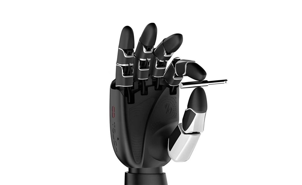
The anthropomorphic dexterous robotic hand was designed with five fingers. The layout was optimized based on human hand proportions, with the middle finger aligned as the central axis. The other fingers are spaced at angular offsets to mimic a natural pose. The palm and finger links were fabricated using Selective Laser Sintering (SLS) with PA12 nylon for a favorable strength-to-weight ratio, while the FPAs were custom-made. The key structural parameters of the finalized dexterous robotic hand are summarized below.
| Finger | Angle to Central Axis (degrees) | Joint 1 Length (mm) | Joint 2 Length (mm) |
|---|---|---|---|
| Index | 20 | 50 | 50 |
| Middle | 0 | 50 | 50 |
| Ring | 20 | 50 | 50 |
| Little | 40 | 40 | 40 |
| Thumb | 45 (relative to index) | 35 | 30 |
The total weight of the hand assembly is approximately 120g, making it relatively lightweight for its complexity.
Myoelectric Control Strategy and Algorithm
The control paradigm for the dexterous robotic hand is centered on interpreting human intent via sEMG signals. The fundamental principle is that specific limb movements generate characteristic patterns of electrical activity in the associated muscle groups. By capturing and decoding these patterns, we can estimate the intended motion and translate it into control commands for the robotic hand. This forms a human-in-the-loop system where the user’s physiological signals directly govern the machine’s actions.
System Architecture
The overall control system is divided into three primary segments:
- Signal Processing & Intent Decoding (Host PC): This module acquires raw sEMG signals from electrodes placed on the user’s forearm. Advanced signal processing algorithms extract relevant features which are then classified by a pattern recognition algorithm (e.g., a neural network) to identify the intended finger motion. Finally, a continuous mapping algorithm converts the processed sEMG signal into target joint angle trajectories.
- Pneumatic Actuation Circuit: This subsystem provides the controlled pressurized air to the FPAs. Its core components are an air compressor, filter-regulator units, and ITV0050-3BS electro-pneumatic proportional valves from SMC Corporation. These valves precisely regulate output air pressure based on an analog input voltage command.
- Joint-Level Servo Controller: This low-level controller receives the target joint angle from the host PC and executes a closed-loop position control. It commands the proportional valve via a voltage signal, reads the actual joint angle from a magnetic encoder (AS5045) mounted on the joint, and adjusts the valve command to minimize the angle error.
Control Algorithm Formulation
The core algorithm translates the extracted sEMG signal feature into a valve control voltage. The proportional valve exhibits a linear input-output characteristic. For a $0-10V$ input range, the output pressure $P_{valve}$ is:
$$ P_{valve} = 0.09 \cdot V_{input} $$
where $V_{input}$ is in Volts and $P_{valve}$ is in MPa.
The mapping from sEMG to joint angle proceeds as follows:
Step 1: Feature Normalization. The feature value $f_m$ extracted from the sEMG signal is normalized to a $[0, 1]$ range:
$$ f = \frac{f_m – f_{min}}{f_{max} – f_{min}} $$
where $f_{max}$ and $f_{min}$ are the maximum and minimum values of the feature curve for a given session.
Step 2: Angle Trajectory Generation. The normalized feature $f$ is scaled to the desired joint angle range:
$$ \theta_{EMG} = f \cdot (\theta’_{max} – \theta’_{min}) $$
Here, $\theta_{EMG}$ is the target joint angle, and $\theta’_{max}$ and $\theta’_{min}$ are the predefined maximum and minimum joint limits (e.g., $90^\circ$ and $0^\circ$).
Step 3: Pressure-Angle Conversion. The target angle $\theta_{EMG}$ is converted to the required pressure differential $\Delta P$ using the inverse of the joint models stated earlier (Eq. 1 for Joint 1, Eq. 2 for Joint 2).
Step 4: Valve Voltage Calculation. Finally, the required pressure is converted to the valve input voltage using the valve’s linear model. For Joint 1, the composite mapping from sEMG feature to valve voltage is:
$$ V_{input1} = \frac{200E t_1}{9 r_1} \cdot \frac{ \frac{L_1 \theta_1}{2} \cot\left(\frac{\theta_1}{2}\right) + H_1\theta_1 – L_1 }{ \frac{L_1 \theta_1}{2} \cot\left(\frac{\theta_1}{2}\right) + H_1\theta_1 } $$
A similar composite function $V_{input2}$ is derived for Joint 2. This end-to-end algorithm allows a continuous stream of sEMG data to generate a continuous, proportional control signal for the dexterous robotic hand.
System Implementation and Software
Hardware Platform
The experimental platform integrates biosignal acquisition, pneumatic actuation, and real-time control. The sEMG signals are captured using a wireless Delsys Trigno system. The pneumatic circuit is built around SMC ITV valves. Each finger joint’s servo controller is based on a dsPIC30F4012 microcontroller, which performs the DA conversion for valve control, reads the magnetic encoder via SPI, and communicates with the host PC over a CAN bus network. This distributed architecture ensures robust and responsive low-level control for each digit of the dexterous robotic hand.
Software Design
The software is partitioned across two environments:
- sEMG Processing & High-Level Control (MATLAB): This module handles real-time sEMG signal acquisition, filtering, feature extraction (using algorithms like amplitude-based methods), and motion intent classification. It executes the high-level mapping algorithm to generate the target angle streams for all joints.
- Supervisory Control & GUI (Delphi): This application serves as the main system interface. It receives target angles from MATLAB, forwards them to the appropriate joint controllers via CAN bus, and displays real-time feedback data such as desired vs. actual joint angles. It provides visualization and system status monitoring.
The software ensures a seamless flow from biological signal to physical actuation of the dexterous robotic hand, closing the loop through position feedback.
Experimental Validation and Analysis
Experiments were conducted to evaluate the precision of the myoelectric control system in positioning the joints of the dexterous robotic hand. The task involved generating various finger flexion motions while recording sEMG. The processed signal created a target angle profile for a specific joint, which the low-level controller then tracked by adjusting the pneumatic pressure.
For conciseness, we present detailed results for the index finger’s distal joint (Joint 2). The target angle profile (ranging from $0^\circ$ to $90^\circ$) and the actual achieved angles were recorded at several key points. To account for material viscoelasticity, a brief stabilization pause was included after each pressure change.
| Data Point | Target Angle (°) | Actual Angle (°) | Absolute Error (°) | Relative Error (%) |
|---|---|---|---|---|
| 1 | 0.0 | 0.0 | 0.0 | 0.0 |
| 2 | 1.0 | 0.9 | 0.1 | 10.0 |
| 3 | 3.0 | 2.8 | 0.2 | 6.7 |
| 4 | 14.8 | 13.6 | 1.2 | 8.1 |
| 5 | 17.3 | 16.9 | 0.4 | 2.3 |
| 6 | 26.5 | 26.2 | 0.3 | 1.1 |
| 7 | 54.9 | 53.7 | 1.2 | 2.2 |
| 8 | 53.7 | 52.8 | 0.9 | 1.8 |
| 9 | 63.2 | 62.7 | 0.5 | 0.8 |
| 10 | 70.9 | 69.8 | 1.1 | 1.6 |
| 11 | 90.0 | 88.2 | 1.8 | 2.0 |
| 12 | 74.0 | 73.6 | 0.4 | 0.54 |
| 13 | 56.5 | 54.9 | 1.6 | 2.8 |
| 14 | 46.1 | 45.5 | 0.6 | 1.3 |
| 15 | 29.5 | 28.2 | 1.3 | 4.4 |
| 16 | 12.3 | 11.8 | 0.5 | 4.1 |
The average relative error, excluding the initial zero point where error is trivially zero, was calculated to be approximately 3.3%. The error profile shows a distinct pattern: higher errors at the very initiation of motion (up to 10%), which rapidly decrease and stabilize around 1-2% during the main movement phase, with a slight increase again as motion ceases. This is attributed to the dynamics of the pneumatic system. The initial transient involves filling the FPA cavity and overcoming static friction, leading to a slight overshoot in required pressure. Once the airflow stabilizes, the closed-loop position control performs effectively, maintaining high fidelity between the sEMG-derived command and the actual joint position. The results validate that the proposed myoelectric control scheme can achieve precise proportional control of the dexterous robotic hand‘s joints.
Conclusion
This work presented the comprehensive development of a biomimetic dexterous robotic hand and its novel myoelectric control system. The mechanical design successfully leveraged Flexible Pneumatic Actuators to create a lightweight, compliant hand structure that closely mimics the kinematics of its biological counterpart. The proposed control strategy represents a significant shift from conventional methods by utilizing surface EMG signals to establish an intuitive, proportional control interface. The implemented algorithm seamlessly maps continuous muscle activity into continuous joint angle trajectories. The integrated hardware and software platform demonstrated the feasibility of this approach, with experimental results confirming a high level of control accuracy. The dexterous robotic hand system, combining soft actuation with biosignal control, holds considerable promise for advancing applications in areas requiring sophisticated manipulation and direct human-robot collaboration, such as advanced prosthetics, rehabilitation robotics, and adaptable robotic assistants for complex tasks.