
In modern manufacturing, industrial robots have become a core driver for enhancing production efficiency, optimizing cost structures, ensuring product quality, and improving operational safety. The continuous advancement in intelligence and automation levels of industrial robots is leading a profound transformation in industrial production models. However, failures in industrial robot systems can directly cause production line interruptions, leading to delays, increased defect rates, and significant economic losses. The rotary vector reducer, as a key component of industrial robots, is widely used in heavy-duty areas such as robot shoulders due to its exceptional load-bearing capacity and high rigidity. The performance of the rotary vector reducer not only determines the positioning accuracy and repeatability of industrial robots but also deeply impacts the overall production efficiency and product quality of equipment manufacturing enterprises. Its technical parameter optimization is strategically irreplaceable for ensuring stable operations in modern manufacturing. With the rapid development of industrial internet and artificial intelligence technologies, building real-time, intelligent fault diagnosis data acquisition platforms has become a crucial breakthrough in enhancing equipment health management.
Traditional fault diagnosis data acquisition systems often rely on single-type sensor data, and platform designs lack compatibility, typically only testing specific types of reducers. In this study, I design an integrated multi-sensor data acquisition platform to dynamically capture multi-dimensional operational data such as vibration, temperature, and noise from the rotary vector reducer. This provides a high-quality data foundation for establishing deep learning-based fault prediction models, promoting the transition of industrial robot maintenance modes to predictive maintenance, reducing lifecycle maintenance costs of key components, and ensuring continuous and efficient operation of smart manufacturing lines. This article details the design process, hardware selection, structural component development, and testing of the platform.
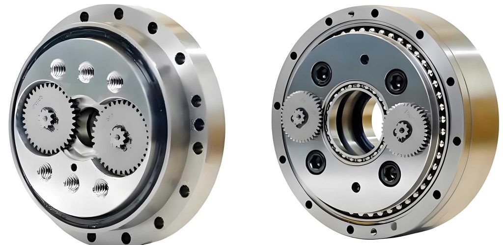
The rotary vector reducer is renowned for its multi-stage composite structure, which exhibits high complexity. Its core components consist of precision mechanical parts working in synergy, primarily including the central gear shaft, planetary gear set, double cycloidal pinwheel, needle tooth pair, and power output shaft. The basic structure is as follows:
- Central Gear: Engages with circumferentially distributed planetary gears to convert high-speed rotational motion into the initial power source for primary reduction transmission, forming the starting node of the entire transmission chain.
- Planetary Gears: Constitute the core components of the primary reduction mechanism, achieving speed reduction and load distribution through circumferential layout while maintaining transmission ratio stability and effectively enhancing torque-bearing capacity.
- Cycloidal Gears: Serve as key actuating mechanisms for secondary transmission. Two cycloidal pinwheels with a constant phase difference of 180° are driven by a three-crank conjugate eccentric mechanism, forming a dynamically balanced system.
- Needle Teeth: Eliminate axial forces through double-row symmetric arrangement, ensuring continuity and reliability of the transmission process.
- Output Shaft: Acts as the terminal actuating element of the transmission chain, integrating previous stage power through spline connections and transmitting the reduced and torque-amplified rotational motion to the actuator.
Under industrial conditions, the rotary vector reducer is subjected to multiple factors such as alternating loads, impact vibrations, and assembly stresses, leading to gradual performance degradation and functional failures in key components. Common faults include:
- Planetary Gear System Faults: During operation, the rotary vector reducer undergoes periodic alternating loads, which exacerbate typical faults such as gear fatigue pitting, local spalling, adhesive wear, and tooth breakage, resulting in significantly increased noise and difficulty maintaining transmission accuracy stability.
- Cycloidal Gear System Faults: Due to large meshing areas and high load-bearing capacity, long-term operation can lead to failure modes including fatigue fracture, tooth surface gluing, contact fatigue-induced pitting, tooth surface wear, and plastic deformation.
- Crankshaft Faults: Common failure modes include fatigue bending deformation, structural instability, and crankshaft fracture, often related to sustained eccentric loads and with higher occurrence probability under high-load, high-cycle conditions.
- Bearing Faults: The rotary vector reducer bears substantial axial and radial forces during operation, and bearing performance limits the overall level of the reducer. Common failures include wear or fracture of rollers or balls, and cage breakage.
- Other Faults: These primarily involve seal wear and aging, insufficient bolt preload, and cracking in the pin gear housing and spacer rings.
To address these faults, a comprehensive data acquisition platform is essential. The platform design scheme adopts an integrated approach common in current domestic rotary vector reducer fault diagnosis, integrating multiple performance parameter acquisition functions into a unified system. This scheme offers advantages such as low cost, small footprint, high data acquisition efficiency, and the ability to perform various performance tests under identical operating conditions.
The overall platform structure consists of a servo motor, servo driver, three-axis temperature-vibration intelligent sensor, rotary vector reducer, encoder, noise spectrum analyzer, and data acquisition card. The platform surface uses a 6–8 mm thick SUS430 high-permeability stainless steel plate. To enhance stability during operation, vibration damping pads are installed beneath the platform. The reducer mount is fixed on a sliding platform that allows independent movement along guides in the front-back direction, facilitating assembly and disassembly of the rotary vector reducer. To ensure structural stability under load, the main material for the elevated platform is heat-treated steel. The architecture is summarized in Table 1.
| Component | Function |
|---|---|
| Servo Motor | Provides controlled rotational input to the rotary vector reducer. |
| Servo Driver | Controls the servo motor and feedbacks real-time torque and speed. |
| Three-axis Vibration-Temperature Sensor | Measures vibration acceleration in X, Y, Z axes and temperature. |
| Rotary Vector Reducer | Test subject for fault diagnosis. |
| Encoder | Measures rotational speed and position. |
| Noise Spectrum Analyzer | Captures and analyzes noise signals. |
| Data Acquisition Card | Converts analog signals to digital data for computer processing. |
The servo motor is directly connected to the input shaft of the rotary vector reducer via a coupling, while the output shaft is rigidly connected to a fixed load or free end via another coupling. The sliding platform adjusts the axial alignment of the servo motor, rotary vector reducer, and load end to ensure coaxiality. An industrial computer drives the servo motor according to preset speed or torque modes, while the servo driver feedbacks real-time output torque and speed parameters.
During operation, the three-axis vibration-temperature intelligent sensor is directly mounted on the housing surface of the rotary vector reducer, continuously collecting vibration acceleration signals in the X, Y, Z directions and temperature data. The noise spectrum analyzer simultaneously records noise signals during reducer operation and extracts characteristic frequency components through frequency domain analysis. Servo motor operational parameters (e.g., current, power) are transmitted to the industrial computer via the driver bus, combined with load-end feedback to infer dynamic characteristics of the transmission system.
All sensor data are transmitted to the computer via the data acquisition card. Through vibration spectrum analysis, temperature trend comparison, and noise frequency domain feature extraction, the operational status and fault characteristics of the rotary vector reducer are comprehensively assessed. Closed-loop control algorithms dynamically adjust the servo motor input parameters to maintain test condition stability and ensure synchronization of multi-source data.
To meet the overall design requirements, two key points must be addressed:
- Construct a multi-sensor fusion detection system, focusing on optimizing the spatial layout of vibration, temperature, and noise sensors. Dedicated sensor positioning fixtures must be designed to ensure geometric alignment of each detection unit with the power transmission path of the rotary vector reducer, minimizing phase deviation and energy attenuation during signal acquisition.
- Design a universal reducer mounting base that accommodates multiple models of rotary vector reducers, enhancing acquisition efficiency and maintaining platform accuracy during reducer replacement.
For hardware selection, the servo system is chosen based on the rated speed, torque, and power of the rotary vector reducer. In this design, a common rotary vector reducer model is assumed with parameters listed in Table 2. Based on these, a servo motor is selected with parameters in Table 3.
| Parameter | Value |
|---|---|
| Rated Torque | 167 N·m |
| Allowable Start-Stop Torque | 412 N·m |
| Rated Speed | 15 rpm |
| Starting Efficiency | 80% |
| Reduction Ratio | 81 |
| Parameter | Value |
|---|---|
| Power | 750 W |
| Rated Torque | 2.4 N·m |
| Peak Torque | 7.2 N·m |
| Peak Speed | 6000 rpm |
| Rated Speed | 3000 rpm |
Based on calculations, a 750 W servo motor matched with a rotary vector reducer of reduction ratio 81 meets torque, speed, and power requirements with margin, ensuring a reasonable system design.
For data acquisition devices, a three-axis vibration-temperature intelligent sensor is used with key parameters in Table 4. This sensor magnetically attaches to the rotary vector reducer housing, transmitting transient vibration waveforms and temperature values via configured software.
| Parameter | Specification |
|---|---|
| Model | VTall-T163E-A |
| Measurement Range | Vibration: ±16 g; Temperature: -40°C to 125°C |
| Frequency Response | DC to 6 kHz (±3 dB) |
| Resolution | 0.488 mg/LSB |
| Sampling Frequency | 26.667 kHz |
| Operating Temperature | -40°C to 85°C |
| Protection Rating | IP67 |
A noise spectrum analyzer is employed with a measurement range of 20 dB(A) to 143 dB(A) and frequency coverage from 10 Hz to 20 kHz, capable of capturing low-frequency vibrations and high-frequency noise signals generated by faults such as gear wear or bearing damage in the rotary vector reducer. The data acquisition card converts analog current signals from the servo driver into digital data, with a sampling rate set to 1 MS/s and a range of ±10.24 V for high-frequency vibration signals.
In terms of structural design, a slide-rail rotary vector reducer mount is developed using modular mechanical structures made from aluminum alloy 6061. It comprises a slide rail base, indexing fixed mount, and lead screw alignment mount, enabling quick replacement and precise positioning of the rotary vector reducer through pure mechanical linkage. The slide rail base uses a composite layered structure with linear guides as the motion core to decouple upper and lower plates dynamically. The upper carrying plate is fixed to the slide rail via M6 screws, forming a motion unit with high load capacity and precise displacement, while the lower base plate provides stable support. The lead screw alignment mount uses a bidirectional synchronous lead screw transmission mechanism, with V-shaped clamps featuring vulcanized rubber anti-slip layers for self-centering clamping. The indexing fixed mount has circumferential ring hole arrays for radial positioning via M6 bolts, and a locking unit with circular and elliptical slots to adapt to various rotary vector reducer models. Additionally, a servo motor mount is designed to align the motor shaft with the rotary vector reducer platform shaft.
For hardware configuration and testing, the three-axis vibration-temperature sensor is connected to a computer, and its local IP parameters are modified via configuration software (e.g., VibrationMoni). The software allows real-time waveform and spectrum display. The servo driver is configured to output current signals through analog channels, with filtering and dead zones set for accurate monitoring. The noise spectrum analyzer is set to weighting modes, such as Z-weighting, for full-frequency noise energy analysis, with a sampling rate ≥40 kHz and FFT parameters like Hanning window to reduce spectral leakage. Resolution bandwidth is adjusted below 10 Hz to enhance identification of fault characteristic frequencies. The data acquisition card is connected to the servo driver’s output, with triggering modes set to software triggering for synchronization with motor operation, enabling continuous data transmission to the computer.
After installation and configuration, all devices are powered on, and the rotary vector reducer data acquisition platform successfully collects data from various sensors, achieving expected results. Thus, the data acquisition system is feasible and has practical value, providing technical reference for design optimization and fault diagnosis analysis of rotary vector reducers.
To further support fault diagnosis, mathematical models are employed. For instance, vibration signals can be analyzed using Fourier transform to identify characteristic frequencies associated with faults. The vibration acceleration signal $a(t)$ can be expressed as:
$$ a(t) = \sum_{n=1}^{N} A_n \sin(2\pi f_n t + \phi_n) + \epsilon(t) $$
where $A_n$ is the amplitude, $f_n$ is the frequency, $\phi_n$ is the phase, and $\epsilon(t)$ is noise. For a rotary vector reducer, fault frequencies such as gear mesh frequency $f_m$ can be calculated as:
$$ f_m = \frac{N \times \text{shaft speed}}{60} $$
where $N$ is the number of teeth. For planetary gears in a rotary vector reducer, the characteristic fault frequency $f_p$ might be:
$$ f_p = f_m \times k $$
where $k$ is a harmonic integer. Temperature rise $\Delta T$ due to friction or wear can be modeled using thermal dynamics:
$$ \Delta T = \frac{Q}{mc} $$
where $Q$ is heat generated, $m$ is mass, and $c$ is specific heat capacity. Noise level $L$ in decibels can be related to sound pressure $p$:
$$ L = 20 \log_{10}\left(\frac{p}{p_0}\right) $$
with $p_0$ as reference pressure. These formulas aid in feature extraction for fault diagnosis.
In conclusion, this study focuses on the fault diagnosis needs of industrial robot rotary vector reducers, designing and developing a multi-source data acquisition platform. By dynamically monitoring multi-dimensional signals such as vibration, temperature, and noise, the platform provides data support for condition assessment and fault diagnosis of rotary vector reducers. Based on the structural characteristics and typical fault mechanisms of rotary vector reducers, key failure modes are systematically reviewed, identifying vibration, temperature, and noise signals as core parameters for fault characterization. Through integration of servo drive systems, three-axis vibration-temperature sensors, and multifunctional sound level meters, a modular data acquisition platform adaptable to multiple models of rotary vector reducers is constructed. The platform significantly enhances compatibility and replacement efficiency via slide-rail mount design and adjustable alignment mechanisms. For the load characteristics of rotary vector reducers, selection and matching calculations for servo motors, sensors, and data acquisition cards are completed. The multifunctional sound level meter captures non-contact noise signals, extracting fault characteristic frequencies through frequency domain analysis, complementing traditional vibration signal analysis. The designed platform can synchronously acquire multi-source data and achieve feature extraction, verifying its feasibility and data acquisition reliability, laying a solid foundation for subsequent fault diagnosis model construction. Future work may involve implementing machine learning algorithms for automatic fault classification and prediction based on the acquired data.