
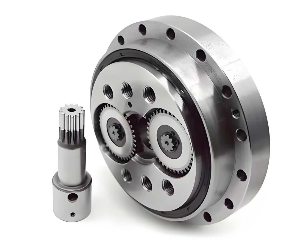
In the field of industrial robotics, the rotary vector reducer plays a critical role due to its high transmission efficiency, wide speed ratio range, compact structure, and superior load-bearing capacity. The performance of the main bearings within a rotary vector reducer directly influences key characteristics such as load capacity, overturning stiffness, transmission accuracy, efficiency, temperature rise, and precision retention. Therefore, comprehensive research on these main bearings is essential for advancing the manufacturing level of reducers, optimizing precision retention, and enhancing overall robot quality. This article presents the development of a dedicated test bench for evaluating the overturning stiffness and fatigue life of main bearings in rotary vector reducers, addressing existing challenges in accurate measurement and verification.
The experimental principles for assessing main bearings in a rotary vector reducer involve two primary aspects: overturning stiffness testing and fatigue life evaluation. Overturning stiffness is defined as the overturning moment applied to the output bearing when the output planet carrier deforms under external load with an inclination angle of 1 arcminute. For a rotary vector reducer, the main bearings are typically paired and mounted between the pin gear housing and the planet carrier. When external loads, including radial load \(W_1\) and axial load \(W_2\), act on the output shaft, the planet carrier experiences deformation with an inclination angle \(\theta\). The overturning stiffness \(M\) is calculated as:
$$ M = \frac{W_1 l_1 + W_2 l_3}{\theta} $$
where \(l_1\) is the distance from the radial load \(W_1\) to the support center of the two main bearings, and \(l_3\) is the distance from the axial load \(W_2\) to the reducer axis. This formula is fundamental for quantifying the rigidity of a rotary vector reducer under moment loads.
For fatigue life testing, the test bench simulates continuous operation under specified loads to determine the endurance of the main bearings. The failure modes, such as fatigue spalling on raceways and balls, are monitored through parameters like temperature rise and iron powder content in the lubricant. The life of main bearings in a rotary vector reducer can be estimated using standardized calculations based on load distributions and material properties. According to ISO/TS 16281:2008, the basic rating life of a bearing is influenced by dynamic equivalent loads and adjustment factors for lubrication and contamination. For a rotary vector reducer’s main bearings, which are often angular contact ball bearings arranged back-to-back, the life calculation must account for preload effects. The maximum contact load on a main bearing can be expressed as:
$$ Q_{\text{max}} = \frac{F_r}{Z J(\varepsilon) \sin \alpha} $$
where \(F_r\) is the radial load on the bearing, \(Z\) is the number of balls, \(J(\varepsilon)\) is the radial integral, and \(\alpha\) is the contact angle. The basic dynamic load rating \(C_r\) for ball bearings is given by:
$$ C_r = b_m f_c (i \cos \alpha)^{0.7} Z^{2/3} D_w^{1.8} $$
where \(b_m\) is a coefficient, \(f_c\) is a factor depending on geometry and material, \(i\) is the number of rows, and \(D_w\) is the ball diameter. The adjusted rating life \(L_{nmr}\) is then:
$$ L_{nmr} = a_1 a_{\text{ISO}} \left( \frac{C_r}{P_{\text{ref},r}} \right)^3 $$
where \(a_1\) is the reliability factor, \(a_{\text{ISO}}\) is the life adjustment factor, and \(P_{\text{ref},r}\) is the dynamic equivalent reference radial load. These formulas provide a theoretical foundation for predicting the fatigue life of main bearings in a rotary vector reducer, but experimental validation is crucial for accuracy.
The main bearing test bench for rotary vector reducers consists of three major subsystems: the mechanical system, the electrical control system, and the measurement software. The mechanical system is designed with a horizontal layout to save space and ensure operational simplicity. Key components include a cast iron flat plate, output shafts, the reducer under test, installation brackets, and loading mechanisms. The cast iron plate is manufactured through whole casting with precision planning and scraping to guarantee structural rigidity and surface accuracy. The power mechanism incorporates a servo motor and driver, providing high-precision, fast, and stable power output. The servo motor transmits torque to the input shaft of the rotary vector reducer via a precision test shaft connected through keys or splines. Paired deep groove ball bearings in bearing housings ensure rotational accuracy and reliable power transmission. The loading mechanism applies precise and stable loads to simulate overturning moments. It features a flexible loading assembly with threaded loaders, support plates, springs, and a base. By applying controlled torque to circumferentially distributed threaded loaders, a constant load is exerted on the support plate, measured accurately by a force sensor. The spring elements compensate for assembly errors while maintaining load precision. This design allows for accurate application of overturning moments to the rotary vector reducer, enabling realistic fatigue and stiffness testing.
The electrical control system integrates data acquisition, motion control, and sensor modules. A programmable logic controller (PLC) manages signals, converting analog outputs to digital commands for the servo motor driver. Sensors such as force sensors, inclinometers, temperature sensors, and iron powder concentration meters monitor test parameters. Data from these sensors are converted to digital signals, recorded by the PLC, and displayed via measurement software through RS485 serial communication. The measurement software, developed using an industrial configuration platform, includes modules for fatigue testing and stiffness testing. It facilitates functions like reducer ID entry, parameter setting, experiment control, data logging, report generation, and historical data追溯. The software interfaces with a database to store and manage operational data, including motor speed, torque, bending moment, inclination angle, and alarm status. This integrated system ensures efficient data collection and analysis for evaluating rotary vector reducer main bearings.
To illustrate the test bench configuration, Table 1 summarizes the hardware and software components used in the system. This setup ensures reliability and accuracy in testing rotary vector reducer main bearings.
| Component | Supplier | Model |
|---|---|---|
| Upper Computer Software | Delta | DIAView SCADA |
| PLC | Delta | DVP-32EH00T3 |
| Servo Motor | Inovance | MS1H2-40C30CD-T331Z |
| Driver | Inovance | SV630PT017I |
| Temperature Sensor | Yangzi | WZP-290 |
| Iron Powder Concentration Meter | Shin Cosmos | SDM-72 |
| Force Sensor | Yuhang | YFLH-4B |
| Inclinometer | Riehen | ACA616T |
Experimental studies were conducted using a rotary vector reducer model RV-125N to validate the test bench’s capabilities. The performance parameters of this rotary vector reducer are listed in Table 2, providing context for the tests.
| Parameter | Value |
|---|---|
| Reducer Model | RV-125N |
| Reduction Ratio | 111 |
| Rated Torque (N·m) | 1225 |
| Rated Speed (r/min) | 15 |
| Allowable Moment M (N·m) | 3430 |
| Main Bearing Contact Angle (°) | 40 |
| Overturning Stiffness (N·m/arcmin) | >1600 |
| Number of Balls | 36 |
| Ball Diameter (mm) | 11.113 |
| Main Bearing Basic Dynamic Load Rating (kN) | 43 |
| Main Bearing Basic Static Load Rating (kN) | 53.8 |
The overturning stiffness tests investigated the relationship between main bearing preload and stiffness, as well as the effect of output shaft rotation angle. For preload variation, three RV-125N reducers with main bearing preloads of 0.04 mm, 0.06 mm, and 0.08 mm were tested. The load was gradually increased from 0 to the allowable moment M, and overturning stiffness values were recorded at different loads. The results, shown in Table 3, indicate that stiffness increases with preload, consistent with bearing theory where higher preload enhances support rigidity. However, stiffness exhibits nonlinear behavior due to structural deformations in the test bench under varying loads.
| Preload (mm) | Overturning Stiffness at Allowable Moment (N·m/arcmin) | Trend |
|---|---|---|
| 0.04 | 1650 | Baseline |
| 0.06 | 1780 | Increase |
| 0.08 | 1850 | Increase |
For output shaft angle variation, the RV-125N reducer was rotated to positions of 0°, 60°, 120°, 180°, 240°, and 360°, and stiffness was measured at each angle under the allowable moment. The data in Table 4 reveal periodic fluctuations in stiffness, attributed to structural asymmetries within the rotary vector reducer that cause cyclic variations in bearing contact rigidity. All measured stiffness values exceeded the performance requirement of 1600 N·m/arcmin, demonstrating the test bench’s accuracy in evaluating rotary vector reducer stiffness.
| Output Shaft Angle (°) | Overturning Stiffness (N·m/arcmin) |
|---|---|
| 0 | 1780 |
| 60 | 1765 |
| 120 | 1775 |
| 180 | 1790 |
| 240 | 1760 |
| 360 | 1780 |
Fatigue performance testing was performed on an RV-125N reducer with a main bearing preload of 0.06 mm. The reducer was operated under a constant overturning moment of 3430 N·m and a torque of 300 N·m at a speed of 15 r/min. Key parameters monitored included housing temperature, noise, and iron powder content in the lubricant. The test continued until signs of failure appeared, such as abnormal temperature rise or increased iron powder concentration. The results, summarized in Table 5, show that the reducer operated for 605 hours before failure. The wear process followed three stages: run-in wear, stable wear, and severe wear. During the run-in stage, temperature and iron powder content rose slightly and then stabilized. In the stable stage, these parameters remained constant. At around 605 hours, a sharp increase in temperature and iron powder indicated entry into the severe wear stage, leading to failure. Post-test inspection revealed fatigue spalling on the main bearing raceways and balls, characteristic of fatigue failure under cyclic stresses. This confirms the test bench’s ability to assess the fatigue life of main bearings in a rotary vector reducer.
| Parameter | Observation |
|---|---|
| Test Duration (hours) | 605 |
| Failure Mode | Fatigue spalling on raceways and balls |
| Temperature Rise at Failure (°C) | Significant increase above 60 |
| Iron Powder Content at Failure | Sharp rise indicating severe wear |
To correlate experimental findings with theoretical predictions, a three-dimensional analytical model of the RV-125N rotary vector reducer was developed in Masta software based on the test conditions. The model simulated the reducer with fixed pin gear housing and applied loads of 3430 N·m overturning moment and 300 N·m torque on the output shaft. Main bearing parameters, including ball count, diameter, contact angle, material strength, surface roughness, lubrication coefficient, contamination coefficient, and preload, were inputted. Life calculations followed ISO/TS 16281, with results for different preloads presented in Table 6. For a preload of 0.06 mm, the simulated life of the main bearing was 538 hours, which is 89% of the actual experimental life of 605 hours. This close agreement validates the test bench’s accuracy in fatigue life verification and underscores the importance of preload in life estimation for rotary vector reducer main bearings.
| Main Bearing Preload (mm) | Simulated Life (hours) | Comparison with Experimental Life (0.06 mm preload) |
|---|---|---|
| 0.04 | 620 | Higher due to lower preload |
| 0.06 | 538 | 89% of actual 605 hours |
| 0.08 | 480 | Lower due to higher preload |
The development of this main bearing test bench for rotary vector reducers effectively addresses challenges in accurately measuring overturning stiffness and verifying fatigue life. The test bench integrates modular mechanical design, flexible loading mechanisms, and intelligent control systems to provide reliable data on rotary vector reducer performance. Experimental results demonstrate that overturning stiffness increases with main bearing preload and varies periodically with output shaft angle due to internal structural characteristics. Fatigue tests reveal typical failure modes, such as raceway spalling, and show that theoretical life predictions align closely with experimental outcomes when preload is considered. These insights contribute to the design and manufacturing optimization of rotary vector reducers, enhancing their reliability and longevity in robotic applications. Future work may involve extending tests to other rotary vector reducer models or exploring the effects of different lubrication conditions on main bearing performance.
In summary, the main bearing test bench for rotary vector reducers represents a significant advancement in evaluation capabilities. By combining precise mechanical loading, comprehensive sensor monitoring, and robust software analysis, it enables detailed investigation of stiffness and fatigue properties. The findings underscore the critical role of main bearings in rotary vector reducer performance and provide a foundation for further research and development in high-precision robotics components. As the demand for durable and efficient rotary vector reducers grows, such test benches will remain invaluable for quality assurance and innovation in the field.