
In recent years, the rapid progress of space exploration has motivated the development of robotic systems capable of assisting or replacing astronauts in complex tasks. Among them, humanoid robots, often referred to as embodied robots, are particularly attractive because of their anthropomorphic morphology, which allows them to operate in workspaces designed for humans. For such robots, the joint is the fundamental actuation unit that determines the overall performance, including payload capacity, motion precision, compactness and reliability. In this thesis, a large-load integrated joint for an embodied robot intended for space applications is systematically developed. The design covers mechanical structure, sensing, driving electronics, FPGA-based control and experimental verification. The proposed joint employs a brushless DC motor in tandem with a harmonic reducer, with hollow shafts for internal wiring. Its overall weight is less than 4.7 kg, and it delivers a maximum output torque of 192.2 Nm, making it well suited for the demanding load requirements of a space humanoid arm. The integrated joint contains an absolute encoder, an incremental encoder, a torque sensor and a fail-safe brake. The control architecture includes position, velocity and torque loops, all implemented on an FPGA platform. A user-friendly upper-computer interface is developed in VB for parameter tuning and real-time monitoring. Extensive experiments, including open-loop PWM tests, closed-loop speed/position control and load torque tests, confirm the feasibility and high load capacity of the developed joint. The results demonstrate that the proposed integrated joint is a promising building block for future space humanoid robots, which are representative embodied robots operating in the challenging space environment.
Chapter 1: Introduction
1.1 Background and Significance
Space exploration has expanded rapidly over the past decades. Astronauts are required to perform extravehicular activities such as station monitoring, orbital debris handling, equipment maintenance, and payload transfer. These tasks are physically demanding and risky. Robotic systems, especially anthropomorphic embodied robots, offer an effective alternative by reducing the need for human extravehicular activity, improving safety, and increasing mission efficiency. The well-known space manipulators such as the Canadianarm and the Japanese JEMRMS have demonstrated the value of space robotics. More recently, NASA’s Robonaut 2, a humanoid embodied robot, was delivered to the International Space Station, marking a new era of in-orbit human-robot collaboration. In China, there is an increasing demand for developing space humanoid robots to support future space station construction and maintenance.
One of the most critical components of a humanoid embodied robot is its joint. A joint must integrate a motor, a reduction mechanism, position/velocity/torque sensors, power electronics, and control algorithms into a compact package. In space applications, the joint must also withstand extreme temperatures, vacuum, radiation and microgravity, while providing high torque density, high precision, hollow wiring and modularity. The design and manufacture of such a large-load integrated joint is therefore a key technological challenge.
1.2 Literature Review
Several space robotic arms have been developed with different joint configurations. The European Robotic Arm (ERA) uses conventional planetary gear reducers, achieving high output torque but at the cost of a large mass. The NASA Robonaut 2 integrates hollow motors and harmonic drives to achieve compactness and precision. The German Justin robot uses a similar architecture and achieves a joint torque of 270 Nm at the shoulder. In China, the HIT manipulator joint developed at Harbin Institute of Technology uses a hollow motor combined with a harmonic reducer, providing a torque of 130 Nm. However, for a humanoid arm carrying a 100 kg payload in orbit, the required joint torque is more than 200 Nm. Therefore, a new joint with higher torque density and smaller envelope size is needed.
Among the various possible joint configurations, the hollow motor plus harmonic reducer scheme is the most promising because it offers the advantage of a central hole for cable routing, high gear ratio, low backlash, and a coaxial structure that reduces the overall size. In contrast, configurations where the motor is perpendicular to the reducer or arranged in parallel tend to enlarge the joint footprint. The differential single-joint dual-degree-of-freedom configuration may couple the two motor controls and degrade precision. Consequently, the tandem configuration is selected for the present work.
1.3 Main Contributions and Organization
The main contributions of this thesis are as follows:
- Requirement analysis of a large-load integrated joint for a space humanoid robot is carried out, leading to a set of quantitative specifications.
- A compact mechanical architecture is designed, using a brushless DC (BLDC) motor, a harmonic reducer, an electromagnetic brake, a cross-roller bearing, an absolute encoder, a torque sensor and an incremental encoder. Key components are selected through rigorous load and life calculations, and critical parts are verified by finite-element simulation.
- An FPGA-based joint controller is developed, including a power driver board, an isolated acquisition board, and a core FPGA board. The software implements position, velocity and torque loops, and the entire system is verified by simulation.
- A prototype is integrated, and an upper-computer software interface is developed in VB. Experiments are conducted to validate open-loop PWM operation, closed-loop control and heavy-load performance.
The remainder of this paper is organized as follows. Chapter 2 presents the requirement analysis of the integrated joint. Chapter 3 describes the mechanical design, component selection, and verification calculations. Chapter 4 develops the FPGA-based driving controller, including hardware and software modules. Chapter 5 discusses the prototype integration, upper-computer software and experimental results. Finally, the conclusion summarizes the achievements and describes future work.
Chapter 2: Requirement Analysis for a Space Humanoid Robot Joint
2.1 Overview of the Humanoid Robot System
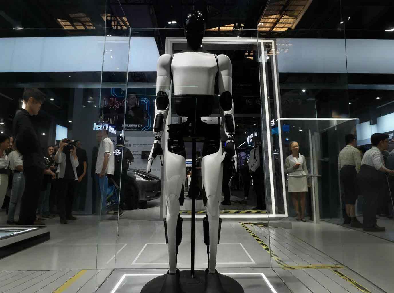
The space humanoid robot considered in this work is an embodied robot consisting of a head, two arms, two legs and a waist. The head provides stereo vision with pan and tilt motions. Each arm has 7 degrees of freedom: shoulder (3 DOF), elbow (2 DOF) and wrist (2 DOF), together with a dexterous hand. Each leg has 5 DOF and an end effector clamp. The waist has 2 DOF for rotating and pitching of the upper body. The arm length is approximately 1.21 m. The robot is designed to work both in orbit and on the ground for testing. It must be able to handle large payloads, e.g., a 100 kg object, with a maximum joint angular acceleration of 1 rad/s², and maintain a high end-effector positioning accuracy of 20 mm.
2.2 Decomposition of the Integrated Joint System
The integrated joint system is decomposed into three principal subsystems: the mechanical system, the hardware system, and the control system. The mechanical system includes the motor, reducer, brake, bearing, sensors and housings. The hardware system comprises power conditioning, signal isolation, analog-to-digital conversion, communication interfaces, and gate drive circuitry. The control system consists of algorithms implemented in FPGA and an upper-computer software system. To achieve module-level replacement, the joint must possess standard mechanical and electrical interfaces. In addition, the joint should be designed as a hollow structure to route cables internally, thereby preventing cable entanglement during repetitive motions.
2.3 Joint Configuration Comparison
Several configurations have been used in existing space robotic arms. The parallel configuration, where the motor and reducer are mounted side by side, results in a large axial dimension. The perpendicular configuration, where the motor axis is perpendicular to the output axis, reduces axial length but increases the radial envelope and complicates hollow wiring. A single-joint dual-DOF configuration may use two motors and one differential mechanism, which is beneficial for high torque but difficult to control accurately. The tandem configuration, consisting of a hollow BLDC motor directly connected to a harmonic reducer, has the following advantages:
- No additional gear box, hence low backlash and high transmission accuracy;
- Coaxial structure with a central hole allowing cable routing;
- Compact axial and radial dimensions;
- High reliability through fewer moving parts;
- Modularity, enabling easy replacement of the whole joint.
Therefore, this thesis adopts the tandem configuration with a hollow motor and a harmonic reducer.
2.4 Derivation of Performance Specifications
The load requirement is derived from the arm dynamic model. As shown in the simplified model, the arm is assumed to have uniformly distributed mass. The total arm mass is \(m=45\text{ kg}\), and the payload at the end effector is \(M=100\text{ kg}\). The required joint torque is:
$$T = \left(\frac{1}{3} M r^2 + m r^2\right)\beta $$
where \(r\) is the distance from the shoulder joint to the load, and \(\beta\) is the angular acceleration. Substituting \(r=1.21\text{ m}\), \(\beta=1\text{ rad/s}^2\) and the masses gives:
$$T = \frac{1}{3}(100)(1.21)^2 + 45(1.21)^2 \approx 168.37\text{ Nm}$$
Applying a safety factor \(k=1.2\), the required output torque is:
$$T_{\text{joint}} = 1.2 \times 168.37 \approx 202\text{ Nm}$$
For positioning accuracy, the relation between the end-effector error \(\Delta l\) and the shoulder joint angular error \(\Delta \theta\) is:
$$\Delta \theta = \frac{\Delta l}{L}$$
With \(\Delta l = 20\text{ mm}\) and \(L=1.21\text{ m}\), we obtain:
$$\Delta \theta \approx 0.0165\text{ rad} \approx 0.95^\circ$$
This corresponds to a transmission error of less than 5% of the commanded angle, which can be satisfied by a high-precision harmonic reducer. The maximum output speed required is 21.5 r/min. Additionally, the joint must have a central hollow diameter of at least 19 mm, a total mass not exceeding 4.7 kg, and a maximum radial envelope of 165 mm × 130 mm. The final specifications are listed in Table 2-1.
| Parameter | Value |
|---|---|
| Rated output torque | ≥200 Nm |
| Total mass | ≤4.7 kg |
| Envelope dimensions | 165 mm × 130 mm |
| Output speed | ≥21.5 r/min |
| Positioning accuracy | ≤5% of travel |
| Hollow shaft diameter | ≥19 mm |
Chapter 3: Mechanical Design and Verification
3.1 Overall Structural Scheme
The mechanical architecture of the integrated joint is shown in Figure 3-1 (not displayed here). The major components are connected coaxially as follows: a hollow BLDC motor is coupled to a harmonic reducer through a motor shaft. An electromagnetic brake is mounted on the motor shaft to prevent motion when power is off. A cross-roller bearing supports the output flange, while an absolute encoder with SSI interface is installed between the circular spline and the flexspline of the harmonic reducer to measure the joint angle directly. A torque sensor is located between the flexspline and the output flange. An incremental optical encoder is attached to the rear end of the motor to measure the motor speed. The high-speed and low-speed sections are separated by a central wiring hole. All sensor wires and power cables pass through the central hole, facilitating a clean and safe assembly.
3.2 Component Selection
To meet the stringent requirements of small axial length, small outer diameter, large inner diameter, light weight, and high precision, the following components are selected. The BLDC motor model is S-76-35-B, with a rated power of 450 W, a maximum speed of 5000 r/min, and a mass of 0.64 kg. The harmonic reducer is a CSF-32-160-2A-GR with a gear ratio of 160:1, a rated torque at 2000 rpm of 96 Nm, a peak repeated torque of 261 Nm, and a mass of 0.56 kg. The absolute encoder is a Netzer DS-90-64-SH-S0, 19-bit resolution, SSI output, with a mass of 0.05 kg. The torque sensor is a customized SRI-M2202 with a range of 250 Nm and a mass of 0.19 kg. The brake is customized with a static holding torque of 550 Nm and a mass of 0.92 kg. The incremental encoder is a Renishaw RLM2I with 38000 pulses per revolution and differential A,B output, mass 0.05 kg. Table 3-1 summarizes the component details.
| Component | Model | Mass (kg) | Outer diameter (mm) | Inner diameter (mm) |
|---|---|---|---|---|
| BLDC motor | S-76-35-B | 0.64 | 75.97 | 30.02 |
| Harmonic reducer | CSF-32-160-2A-GR | 0.56 | 110 | 30 |
| Absolute encoder | DS-90-64-SH-S0 | 0.05 | 90 | 50 |
| Torque sensor | SRI-M2202 | 0.19 | 100 | 20 |
| Brake | Custom | 0.92 | 98 | 30.02 |
| Incremental encoder | RLM2I | 0.05 | 47.5 | 40 |
3.3 Verification of the Harmonic Reducer
The harmonic reducer is the key component that determines the output torque and life. It is verified according to the standard procedures of the manufacturer. The typical operating cycle is described by the load sequence: start-up torque \(T_1=200\text{ Nm}\) for \(t_1=0.3\text{ s}\) at speed \(n_1=10\text{ r/min}\); normal running torque \(T_2=120\text{ Nm}\) for \(t_2=3\text{ s}\) at speed \(n_2=20\text{ r/min}\); deceleration torque \(T_3=80\text{ Nm}\) for \(t_3=0.4\text{ s}\) at speed \(n_3=10\text{ r/min}\); and idle \(T_4=0\) for \(t_4=0.2\text{ s}\). The impact torque is \(T_s=350\text{ Nm}\) with \(t_s=0.15\text{ s}\) at \(n_s=20\text{ r/min}\), and the desired life is \(L_{10}=7000\) hours. The average output torque is computed as:
$$T_{av} = \frac{\sum_{i=1}^{3} T_i \cdot n_i \cdot t_i}{\sum_{i=1}^{3} n_i \cdot t_i} = \frac{200\times10\times0.3 + 120\times20\times3 + 80\times10\times0.4}{10\times0.3 + 20\times3 + 10\times0.4} \approx 124.64\text{ Nm}$$
This value is less than the allowable average torque of 151 Nm for the selected model. The average output speed is:
$$n_{oav} = \frac{\sum_{i=1}^{3} n_i t_i}{\sum_{i=1}^{3} t_i} \approx 17.18\text{ r/min}$$
Then the average input speed is:
$$n_{iav} = n_{oav} \times 160 = 2748.7\text{ r/min} < 5600\text{ r/min}$$
and the maximum input speed is:
$$n_{imax} = 21.5 \times 160 = 3440\text{ r/min} < 7000\text{ r/min}$$
The peak torque \(T_1 = 200\text{ Nm}\) is below the allowable peak of 261 Nm, and the impact torque \(T_s = 350\text{ Nm}\) is below the instantaneous allowable maximum of 359 Nm. The permissible number of impact cycles is checked as:
$$N = \frac{1.0\times10^4}{\frac{2}{60} n_s t_s} \approx 1.5\times10^4 > 1.0\times10^4$$
The reducer life is estimated by:
$$L_{10} = 7000 \left(\frac{T_r}{T_{av}}\right)^3 \frac{n_r}{n_{iav}} = 7000 \left(\frac{96}{124.64}\right)^3 \frac{2000}{2748.7} \approx 2307\text{ h}$$
Although this life is lower than the desired 7000 h, it exceeds the 1800 h maintenace-free interval required by the mission. Therefore, the selected harmonic reducer is acceptable.
3.4 Verification of the Output Cross-Roller Bearing
The output bearing is a cross-roller bearing CRBS10008-VUU with an inner diameter of 100 mm, outer diameter of 116 mm, and width of 8 mm. Its dynamic load rating is \(C=9850\text{ N}\) and static load rating \(C_0=19300\text{ N}\). The bearing receives a radial force \(F_r=230.3\text{ N}\), an axial force \(F_a=230.3\text{ N}\), and an overturning moment \(M=206\text{ Nm}\). The pitch circle diameter is \(D_{pw}=108\text{ mm}\). The static equivalent radial load is:
$$P_{0r} = 0.44 F_r + F_a + \frac{2M}{D_{pw}} = 0.44\times230.3 + 230.3 + \frac{2\times206000}{108} \approx 4146.45\text{ N}$$
The static safety factor is:
$$f_s = \frac{C_0}{P_{0r}} = \frac{19300}{4146.45} \approx 4.65 > 3$$
Since the operating condition demands high rotation accuracy, \(f_s\) must be at least 3; the computed value satisfies this requirement. The dynamic equivalent radial load is then:
First, check the ratio:
$$\frac{F_a}{F_r + \frac{2M}{D_{pw}}} = \frac{230.3}{230.3 + 3814.8} \approx 0.057 < 1.5$$
Thus \(X=1\), \(Y=0.45\), and
$$P_r = XF_r + Y\left(F_a + \frac{2M}{D_{pw}}\right) = 230.3 + 0.45\times(230.3+3814.8) \approx 4148.75\text{ N}$$
Applying the load factor \(f_w=1.5\) for normal operation:
$$P_R = f_w P_r = 1.5 \times 4148.75 = 6223.12\text{ N}$$
The basic dynamic life is:
$$L_{10} = \left(\frac{C}{P_R}\right)^{10/3} = \left(\frac{9850}{6223.12}\right)^{10/3} \approx 64.62 \times 10^6 \text{ revolutions}$$
The corresponding life in hours is:
$$L_h = \frac{10^6}{60 n} L_{10} = \frac{10^6}{60 \times 21.5} \times 64.62 \approx 50092\text{ h} > 1800\text{ h}$$
Thus the cross-roller bearing is adequate.
3.5 Bolt Strength Verification
The most critical bolted connection is located between the flexspline and the output flange. The connection is modeled as a bolt group subjected to an external torque \(T=220\text{ Nm}\). The shear force on each bolt is:
$$F_s = \frac{T}{n r}$$
where \(r=23\text{ mm}\), \(n\) is the number of bolts, and the bolt diameter is \(d_0=3\text{ mm}\). The shear strength condition is:
$$\tau = \frac{4 F_s}{\pi d_0^2 m} \le [\tau]$$
with \(m=1\), \([\tau] = \sigma_s / S\), \(\sigma_s=240\text{ MPa}\), \(S=3\). Substituting gives:
$$n \ge \frac{4 T S}{\pi d_0^2 r \sigma_s} = \frac{4 \times 220000 \times 3}{\pi \times 3^2 \times 23 \times 240} \approx 5.64$$
Therefore, at least 6 bolts of M3 are required. The design uses 6 bolts, satisfying the strength requirement.
3.6 Motor Bearing Verification
The motor bearing must withstand the axial force generated by the harmonic reducer. For a gear ratio above 80, the axial force is calculated by:
$$F_a = 2 \times 0.07 \times \frac{T}{D} \tan 20^\circ$$
where \(T=250\text{ Nm}\) (instantaneous maximum torque) and \(D=0.00254\text{ m}\) (a characteristic diameter of the harmonic reducer). Thus:
$$F_a = 2 \times 0.07 \times \frac{250}{32 \times 0.00254} \tan 20^\circ \approx 156.7\text{ N}$$
The selected deep-groove ball bearing 6708-2RS has a dynamic load rating \(C_r=2519\text{ N}\) and static load rating \(C_{0r}=2234\text{ N}\). The equivalent dynamic load is computed with \(X=0.56\), \(Y=1.00\) and impact factor \(f_p=1.2\):
$$P = f_p (X F_R + Y F_A) = 1.2 \times (0.56 \times 0 + 1.00 \times 156.7) \approx 188.04\text{ N}$$
The bearing life is:
$$L_h = \frac{10^6}{60 n} \left(\frac{C_r}{P}\right)^3 = \frac{10^6}{60 \times 2748.7} \left(\frac{2519}{188.04}\right)^3 \approx 14576\text{ h}$$
This value far exceeds the mission life, so the bearing is safe.
3.7 Finite-Element Analysis of Critical Parts
To ensure structural safety, the output flange and the hollow shaft are analyzed with ANSYS. The output flange is made of structural steel. A mesh size of 1.5 mm is used. The boundary condition applies an overturning moment of 206 Nm and a radial pressure of 230 N on a 30° arc. The analysis results show that the maximum von Mises stress is 22.06 MPa, the maximum strain is 1.33×10⁻⁴, and the maximum displacement is 0.00117 mm. These values are well below the yield strength, confirming the rigidity of the flange. For the hollow shaft, a mesh size of 1 mm is used, and a tensile force of 200 N is applied at the end. The maximum stress is 190.4 MPa, the maximum strain is 9.91×10⁻⁴, and the maximum displacement is 0.526 mm. The stress is relatively high, but it is within the allowable range for structural steel under a margin; these results provide design guidance for subsequent optimization, such as increasing the local fillet radius or changing the material to a higher-strength alloy.
3.8 Final Mechanical Configuration
Based on the above analysis, the final mechanical structure is shown in the following cross-sectional layout. From the motor side to the output side, the order is: electromagnetic brake, incremental encoder, BLDC motor, harmonic reducer, absolute encoder, torque sensor and output flange. The low-speed side is supported by the cross-roller bearing, which is mounted between the fixed flange and the output flange. The motor outer casing is connected to the fixed flange, while the output flange connects to the next link. The central hole with diameter larger than 19 mm allows all cables to pass through the entire joint. The assembled joint measures 163 mm in outer diameter and 129 mm in axial length, with a total mass of 4.65 kg. These values satisfy the design specifications.
Chapter 4: FPGA-Based Joint Driving Controller
4.1 Introduction to BLDC Motor Control
The integrated joint uses a brushless DC motor as the prime mover. Compared with brushed DC motors, BLDC motors have higher reliability, lower electromagnetic interference, and longer life because they use electronic commutators instead of brushes. The stator windings of the selected motor are connected in star configuration, and the rotor position is detected by three Hall sensors. The motor driver uses a full-bridge inverter with six MOSFETs. The control method is the trapezoidal (six-step) commutation, where only two phases are energized at a time and the third phase is floating. The voltage and current through the motor are controlled by pulse-width modulation (PWM) of the upper MOSFETs, while the lower MOSFETs are commutated according to the Hall sensor states.
4.2 Mathematical Model of the BLDC Motor
For a star-connected BLDC motor, the phase voltage equations are:
$$
\begin{pmatrix} u_A \\ u_B \\ u_C \end{pmatrix}
=
\begin{pmatrix} R_A & 0 & 0 \\ 0 & R_B & 0 \\ 0 & 0 & R_C \end{pmatrix}
\begin{pmatrix} i_A \\ i_B \\ i_C \end{pmatrix}
+
\frac{d}{dt}
\begin{pmatrix} L_A & L_{AB} & L_{AC} \\ L_{BA} & L_B & L_{BC} \\ L_{CA} & L_{CB} & L_C \end{pmatrix}
\begin{pmatrix} i_A \\ i_B \\ i_C \end{pmatrix}
+
\begin{pmatrix} e_A \\ e_B \\ e_C \end{pmatrix}
+
U_n
$$
Because the windings are symmetric and the neutral point is floating, \(i_A+i_B+i_C=0\), \(L_A=L_B=L_C=L\), \(L_{AB}=L_{BC}=L_{CA}=M\). After simplification, we obtain the equivalent circuit per phase with inductance \(L-M\). The electromagnetic torque is given by:
$$T_e = \frac{e_A i_A + e_B i_B + e_C i_C}{\omega}$$
and the mechanical dynamics are:
$$T_e = J \frac{d\omega}{dt} + B \omega + T_L$$
where \(T_L\) is the load torque, \(J\) is the total inertia, and \(B\) is the damping coefficient. A Simulink model was developed to verify the control concept. The velocity loop and current loop both use PI controllers. Figure 4-7 (not shown) demonstrates that the simulated speed and current follow the reference signals with good dynamic performance.
4.3 Hardware Architecture
The overall hardware system is divided into three functional printed circuit boards that share the same geometrical dimensions (110 mm outer diameter and 25 mm inner diameter) to be fitted inside the joint housing:
- Power driver board: integrates the three-phase full-bridge inverter, the high-voltage gate driver IR2130, and shunt resistors for current sensing. The board is designed with carefully placed traces and copper opening to carry high current.
- Isolation and acquisition board: includes optocouplers for isolating PWM signals, operational amplifiers for amplifying the shunt voltage, a TLC549 A/D converter for current acquisition, level-shifting circuits for the encoders and Hall sensors, and a DC-DC power module. The board also provides the connector interfaces for the absolute encoder and torque sensor.
- FPGA core board: contains the FPGA (Cyclone series), configuration circuitry, clock source, reset circuit, power supplies, and RS232 level converters for serial communication with the host computer.
The FPGA receives the absolute position data from the SSI interface and the incremental velocity data from the A/B channels. It also reads the torque sensor data through an external A/D converter, and the motor phase currents through the onboard TLC549. The control algorithm computes the appropriate duty cycle and commutation signals, which are sent to the gate driver through optoisolators. The communication protocol between the host computer and the FPGA is RS232 at 9600 baud, with 8 data bits, no parity, and one stop bit.
4.4 FPGA Software Modules
The FPGA software is written in Verilog HDL and synthesized in Quartus II. The top-level design consists of several modules:
- Clock divider module
- Position acquisition module (SSI interface)
- Velocity acquisition module (quadrature decoder and period measurement)
- Current acquisition module (TLC549 interface)
- PWM generation module
- Commutation module (Hall decoder)
- Serial communication module (UART)
- PID controller module
4.4.1 Position Acquisition Module
The absolute encoder uses the SSI (Synchronous Serial Interface) protocol. The FPGA acts as the master and generates a differential clock. At the first falling edge of the clock, the encoder prepares the data, and at subsequent rising edges it shifts out the bits MSB first. The module implements a finite state machine with states: IDLE, READ, RECEIVE, CONVERSION, and DATA_LOAD. The output is a 19-bit binary word that is directly used as the joint position feedback. The timing simulation verifies that the module correctly extracts the position value after receiving the SSI data.
4.4.2 Velocity Acquisition Module
The incremental encoder outputs two differential signals A and B, from which the FPGA reconstructs two single-ended signals A and B. A four-fold multiplication circuit detects both edges of A and B, producing four times the number of pulses per revolution. The direction is determined by checking the logic level of B at the rising edge of A. A frequency measurement method (T method) is adopted: the four-fold pulse is used as the gating signal, and a counter counts the number of 50 MHz clock cycles between successive pulses. The speed is calculated by:
$$\omega = \frac{60 f}{n p}$$
where \(f=50\text{ MHz}\), \(n\) is the counted number, and \(p=38000\) is the encoder resolution, giving 152000 pulses per revolution after four-fold multiplication. The module was simulated with a 10 µs pulse period and 90° phase shift, and the computed speed matched the theoretical value.
4.4.3 Current Acquisition Module
The phase current is sensed by a shunt resistor in the inverter. The voltage drop is amplified and digitized by a TLC549 8-bit A/D converter. The FPGA controls the chip-select and clock signals according to the TLC549 timing. The state machine for the A/D module includes IDLE, READ, RECEIVE, CONVERSION, and DATA_LOAD. The digitized current value is used as the feedback for the current loop.
4.4.4 PWM Generation Module
The PWM generation module creates a fixed-frequency (e.g., 20 kHz) PWM signal whose duty cycle is proportional to the control output. A 16-bit counter generates a triangular waveform. The control data is compared with the counter value; when data is greater than count, the PWM output is high, otherwise low. The sign bit of the data controls the direction signal. The dead-time compensation is handled by the external gate driver.
4.4.5 Commutation Module
Based on the Hall sensor states and the direction signal, the commutation module determines which of the six MOSFETs should be turned on. The truth table for the motor is stored in combinational logic. The PWM signal is ANDed with the corresponding upper bridge signal; lower bridge signals may be directly on/off. The simulation in Figure 4-38 shows the correct commutation pattern for a 50% duty cycle.
4.4.6 Serial Communication Module
The UART module implements both transmitter and receiver. The transmitter sends a byte with one start bit, 8 data bits, and one stop bit. The receiver samples the incoming data at the baud rate and outputs both the received byte and a data-ready strobe. This module provides the communication link between the host computer and the FPGA.
4.5 PID Controller Design and FPGA Implementation
The control architecture consists of three cascaded loops:
- Position loop: a proportional (P) controller that compares the desired joint angle with the absolute encoder feedback and outputs a velocity reference.
- Velocity loop: a proportional-integral (PI) controller that compares the velocity reference with the incremental encoder feedback and outputs a current reference.
- Current loop: a proportional-integral (PI) controller that compares the current reference with the measured motor current and generates the PWM duty cycle.
The continuous-time PID equation is:
$$u(t) = k_p \left[ e(t) + \frac{1}{T_I} \int_0^t e(\tau) d\tau + T_D \frac{d e(t)}{dt} \right]$$
Discretizing with sampling period \(T\), the incremental PID algorithm is obtained:
$$\Delta u(k) = k_0 e(k) + k_1 e(k-1) + k_2 e(k-2)$$
where
$$k_0 = k_p \left(1 + \frac{T}{T_I} + \frac{T_D}{T}\right),\quad k_1 = -k_p \left(1 + \frac{2T_D}{T}\right),\quad k_2 = k_p \frac{T_D}{T}$$
The controller output is updated by \(u(k) = u(k-1) + \Delta u(k)\). In the FPGA, the PID module is implemented as a finite state machine that computes \(e(k)\), stores past errors, calculates \(\Delta u\), and accumulates the output. A start signal triggers the calculation, and a finish signal indicates completion. The simulation waveform of the PID controller confirms correct operation.
4.6 System-Level Simulation
After integrating all modules in the FPGA software, a system-level timing simulation is performed. The simulation includes the clock divider, SSI data simulation, encoder pulse generation, current wave generation, and serial data input. The overall system correctly responds to the position and velocity commands. The synthesized design consumes a small amount of logic resources, leaving ample room for future enhancements.
Chapter 5: Prototype Integration and Experiments
5.1 Circuit Board Fabrication
The designed printed circuit boards are manufactured and populated. The isolation board includes optocouplers, operational amplifiers, A/D converter, and a DC-DC module. The power board contains the three-phase inverter and gate driver. After soldering, the boards are tested with a multimeter and an oscilloscope to verify correct connections and power supply voltages. The power board is able to deliver the required current with proper heat dissipation.
5.2 Mechanical Assembly and Prototype Integration
All mechanical parts are machined according to the two-dimensional drawings generated from the three-dimensional model. The components are cleaned and assembled in a dust-free environment. The assembly sequence starts with the motor and brake, then the harmonic reducer, the cross-roller bearing, the absolute encoder, and finally the torque sensor and output flange. The total weight of the assembled prototype is 4.65 kg, and the outer dimensions are within the specified envelope. The joint is mounted on a test bench that provides a rigid fixing point and allows payload attachment.
5.3 Upper-Computer Software Design
The host computer software is developed using Microsoft Visual Basic (VB). The graphical user interface is shown in Figure 5-3. It consists of the following areas:
- Serial port settings: selection of COM port, baud rate, and connection status;
- Command sending: buttons for enabling the motor, setting the control mode, and sending target values;
- Joint control: sliders or numeric inputs for position, speed, and torque commands;
- Data reception: displays the real-time joint angle, motor speed, phase current, and torque sensor values;
- Hall state display: shows the three Hall sensor signals;
- Motion planning: implements trapezoidal velocity and acceleration profiles for smooth start and stop;
- Data analysis: plots the time-history curves of selected variables.
The communication protocol uses a frame format with a header, data length, payload and checksum to ensure reliable data transmission. The software receives sensor data every 50 ms, enabling the operator to monitor the joint status in real time. For trajectory planning, the trapezoidal velocity profile is expressed as:
$$
V(t) =
\begin{cases}
A t, & t \le T_a \\[2pt]
V_{\max}, & T_a < t \le T_{total} – T_a \\[2pt]
V_{\max} – A (t – T_{total} + T_a), & T_{total} – T_a < t \le T_{total}
\end{cases}
$$
where \(A\) is the constant acceleration, \(V_{\max}\) is the maximum speed, and \(T_a = V_{\max}/A\). For smoother motion, the acceleration can also be shaped in a trapezoidal manner to avoid jerk discontinuities.
5.4 Open-Loop Control Experiment
The first experiment verifies the open-loop operation of the motor driver. A constant PWM duty cycle is applied, and the phase-to-phase voltage waveforms are observed with an oscilloscope. Figure 5-5 shows the PWM output at a duty cycle of 73%. At this duty cycle, the motor rotates at a speed proportional to the applied voltage. When the duty cycle is increased to 100%, the waveforms become constant high and low signals, as shown in Figure 5-6. The commutation logic correctly energizes the motor phases according to the Hall state, confirming the proper operation of the inverter and the FPGA commutation module.
5.5 Closed-Loop Control Experiment
The closed-loop control experiments are performed to validate the position and velocity feedback loops. The motor is commanded to run at a constant speed, and the sensor data, including the joint angle, motor speed, and current, are recorded through the VB interface. The experimental results demonstrate that the measured speed closely follows the reference value with a small steady-state error. The position control experiment is conducted by commanding a step input to a desired angle; the joint reaches the target position without significant overshoot. The control system is stable under varying load conditions.
5.6 Heavy-Load Experiment
To verify the large-load capability of the integrated joint, a load of \(M=20.2\text{ kg}\) is attached at a horizontal distance of \(L=565\text{ mm}\) from the joint axis, producing a gravitational torque of \(M g L = 20.2 \times 9.81 \times 0.565 \approx 112\text{ Nm}\). During the dynamic test, the joint is driven to rotate at a maximum angular speed of \(3.2\text{ rad/s}\). The acceleration time is 0.25 s. The angular acceleration is \(12.56\text{ rad/s}^2\), and the total required torque is calculated as \(T = J \alpha + M g L\), which yields approximately 192 Nm. The joint successfully carries the load and completes the motion without any signs of failure. The experiment demonstrates that the developed joint meets the design target of greater than 200 Nm peak torque. Table 5-1 lists the measured performance of the final prototype.
| Parameter | Measured value |
|---|---|
| Maximum output torque | 192.2 Nm |
| Total mass | 4.65 kg |
| Envelope dimensions | 163 mm × 129 mm |
| Hollow shaft diameter | 19 mm |
| Maximum output speed | 31.25 r/min |
5.7 Continuous Trajectory Motion Experiment
To achieve a smooth start and stop, the joint is controlled with a trapezoidal velocity and a trapezoidal acceleration profile. The host software computes the reference trajectory in real time and sends it to the FPGA. The experimental curves show that the joint acceleration increases linearly to its maximum value, remains constant, then decreases linearly to zero. This profile eliminates abrupt jumps in jerk and reduces mechanical vibrations. The position tracking error remains small during the whole trajectory. The experimental results confirm the effectiveness of the planning algorithm for an embodied robot joint.
Conclusion
In this thesis, a large-load integrated joint for a space humanoid robot, i.e., an embodied robot, has been systematically developed. The key achievements are summarized as follows:
- A thorough requirement analysis was performed based on the in-orbit tasks of a space humanoid robot. Quantitative specifications for torque, mass, envelope, speed, and accuracy were derived, including an output torque greater than 200 Nm and a hollow diameter of at least 19 mm.
- A mechanical design was completed with a hollow BLDC motor and a harmonic reducer in a tandem configuration. All critical components, including the harmonic reducer, cross-roller bearing, bolts, and motor bearing, were verified through analytical calculations. Finite-element analysis confirmed the structural safety of the output flange and the hollow shaft.
- An FPGA-based joint controller was developed. The hardware includes a power driver board, an isolation and acquisition board, and an FPGA core board. The software realizes position, velocity, and torque control loops, with all necessary sensor acquisition modules and a UART communication block. The control system was simulated in Verilog and validated by timing simulations.
- A prototype joint was assembled, and a VB-based host computer interface was developed. Open-loop PWM tests, closed-loop speed/position experiments, heavy-load tests and continuous trajectory motion experiments were carried out. The prototype achieved a maximum torque of 192.2 Nm, a mass of 4.65 kg, and an envelope of 163 mm × 129 mm, satisfying the design requirements.
The present work demonstrates that the proposed integrated joint is a feasible and reliable actuation module for future space humanoid robots. However, several improvements remain for future research:
- Lightweight materials, such as titanium alloys or carbon-fiber-reinforced composites, can further reduce the mass and increase the payload-to-weight ratio.
- The torque sensor and brake can be custom-designed with smaller dimensions to reduce the overall size and weight of the joint.
- The current BLDC motor uses trapezoidal commutation; adopting field-oriented control (FOC) would improve torque smoothness at low speeds and widen the application scope.
- Domestic components should be developed to reduce dependence on imported parts and lower the cost of future space missions.
Overall, this thesis provides a solid engineering foundation for the development of high-performance actuation units for space embodied robots. The results are also applicable to other demanding applications such as industrial manipulators, humanoid robots on the ground, and exoskeletons.