
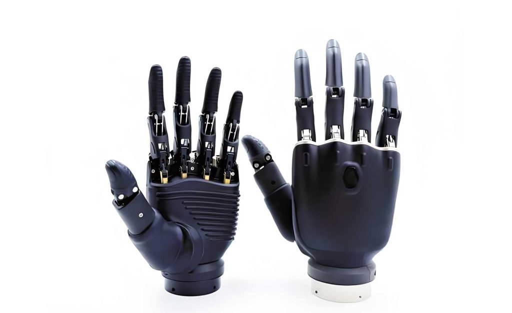
The pursuit of a truly dexterous robotic hand, one that mimics the form, function, and sensory capability of the human hand, represents a pinnacle challenge in robotics. This document details the design philosophy, mechanical implementation, sensory suite, and electronic architecture of the DLR/HIT Hand II, a five-fingered anthropomorphic robotic hand developed through a mechatronic co-design approach. The primary goal was to create a highly integrated, modular, and sensor-rich dexterous robotic hand with a size and mass comparable to an adult human hand, moving significantly beyond previous iterations.
The DLR/HIT Hand II is a 15-degree-of-freedom (DoF) dexterous robotic hand consisting of five identical, modular fingers and an independent palm. Each modular finger possesses 4 joints driven by 3 active DoFs. A key advancement lies in its high integration density; all actuators, sensors, and local processing electronics are embedded within the finger or palm structures, eliminating external tendrils or bulky forearm units. This self-contained design is crucial for system integration, such as mounting on a robot arm. The specifications of this dexterous robotic hand are summarized below:
| Parameter | DLR/HIT Hand II Value |
|---|---|
| Number of Fingers | 5 |
| Total Active DoFs | 15 (3 per finger) |
| Total Joints | 20 (4 per finger) |
| Hand Mass | ~1.5 kg |
| Fingertip Force | >10 N |
| Communication | PPSeCo, CAN, Ethernet |
The core mechatronic achievement is the drastic reduction in finger volume and mass compared to predecessors. This was enabled by adopting a novel brushless DC (BLDC) disc motor with high torque density (20 mm diameter, 10.4 mm length, 15 g mass) coupled with a miniature harmonic drive and timing belt transmission stages. The following table contrasts key actuator components between generations, highlighting the progress in miniaturization for this dexterous robotic hand.
| Component | Previous Generation Motor | DLR/HIT II Disc Motor |
|---|---|---|
| Diameter (mm) | 16.0 | 21.2 |
| Length (mm) | 35.0 | 10.4 |
| Mass (g) | 31 | 15 |
| Reducer Type | Planetary | Harmonic Drive |
| Reducer Mass (g) | 28 | 15 |
The kinematic structure of each finger in this dexterous robotic hand simplifies the human model. It comprises a 2-DOF base joint (abduction/adduction and flexion/extension) and a coupled distal finger segment with two phalanges (proximal and distal interphalangeal joints). The finger’s Denavit-Hartenberg (D-H) parameters, defining its kinematic model, are:
| Joint i | Joint Angle $\theta_i$ | Link Length $a_i$ (mm) |
|---|---|---|
| 1 (Base Flexion) | $0^\circ$ to $90^\circ$ | 0 |
| 2 (Base Abduction) | $-20^\circ$ to $20^\circ$ | 55.0 |
| 3 (PIP Joint) | $0^\circ$ to $90^\circ$ | 25.0 |
| 4 (DIP Joint) | $0^\circ$ to $90^\circ$ | 25.0 |
The forward kinematics for a finger on this dexterous robotic hand can be derived from these parameters. The transformation from the base frame {0} to the fingertip frame {4} is:
$$ {^0T_4} = {^0T_1}(\theta_1) \cdot {^1T_2}(\theta_2) \cdot {^2T_3}(\theta_3) \cdot {^3T_4}(\theta_4) $$
where each homogeneous transformation matrix ${^{i-1}T_i}$ is constructed using the standard D-H convention.
Modular Finger: Mechanical Design and Actuation
The modularity of the finger is fundamental to the design of this dexterous robotic hand. Each finger consists of two primary mechanical subsystems: the 2-DOF base joint and the 1-DOF finger segment with coupled distal joints.
1. The 2-DOF Base Joint: The base joint employs a differential mechanism based on four bevel gears, a robust design proven to provide large output force. Two identical actuation pathways, each comprising a disc motor, a timing belt stage (2.1:1), a harmonic drive (100:1), and a second timing belt (1.1:1), drive the two input gears of the differential. The kinematics of the differential relate the motor angles ($\alpha_1, \alpha_2$) to the base joint angles ($\theta_1$ for flexion, $\theta_2$ for abduction):
$$ \theta_1 = k_1 (\alpha_1 + \alpha_2) $$
$$ \theta_2 = k_2 (\alpha_1 – \alpha_2) $$
where $k_1$ and $k_2$ are constants aggregating the transmission ratios. This configuration means both motors cooperate for flexion/extension and work antagonistically for abduction/adduction, effectively sharing the load and allowing the use of smaller, high-density motors in this dexterous robotic hand.
2. The Finger Segment and Coupled Distal Joints: The finger segment houses the third disc motor within the proximal phalanx. Its drive train consists of a timing belt (2.1:1) and a harmonic drive. Crucially, the harmonic drive’s circular spline is fixed, and its flexspline rotates, directly driving the Proximal Interphalangeal (PIP) joint. The Distal Interphalangeal (DIP) joint is not independently actuated. Instead of a rigid linkage, a steel cable coupling mechanism provides an exact 1:1 motion ratio between the PIP and DIP joints. This cable drive, incorporating a pre-tensioning system, offers a more compact and lightweight solution compared to four-bar linkages, contributing significantly to the slender profile of this dexterous robotic hand.
Multi-Sensory System
A dexterous robotic hand requires rich sensory feedback for autonomous and teleoperated dexterous manipulation. The DLR/HIT Hand II integrates a comprehensive suite of sensors at multiple levels.
1. Joint-Level Sensing: Each joint is equipped with a joint torque sensor (JTS) based on strain gauges. The base joint uses a planar cross-shaped elastic element for 2-axis torque measurement ($\tau_x, \tau_y$), while the finger joints use a uniaxial design. The relationship between strain gauge bridge output voltage $V_{out}$ and applied torque $\tau$ is:
$$ \tau = C \cdot (V_{out} / V_{excitation}) $$
where $C$ is the calibration matrix (scalar for 1-DOF, 2×2 for base joint). Absolute position of the base joint’s differential inputs is measured by potentiometers. Hall-effect-based non-contact sensors measure the angular position of the finger joints.
2. Fingertip Sensing: Each fingertip incorporates a miniaturized 6-axis Force/Torque Sensor (FTS). This sensor features a monolithic elastic body with a full Wheatstone bridge strain gauge configuration on multiple flexures, allowing the measurement of three force components ($F_x, F_y, F_z$) and three torque components ($M_x, M_y, M_z$). The sensor output $\mathbf{S}$ is related to the applied wrench $\mathbf{W}$ via a decoupling matrix $\mathbf{D}$:
$$ \mathbf{W} = \mathbf{D} \cdot \mathbf{S}, \quad \mathbf{W} = [F_x, F_y, F_z, M_x, M_y, M_z]^T $$
A dedicated microcontroller inside the sensor housing performs signal conditioning, decoupling, and digital communication.
3. Additional Sensing: Motor commutation is achieved via integrated Hall sensors. Temperature sensors on driver boards monitor thermal conditions. An inertial measurement unit (IMU) or accelerometer on the palm board estimates hand orientation for gravity compensation. A tactile sensor array based on piezoresistive materials is under development for distributed contact sensing, further enhancing the perceptual capability of this dexterous robotic hand.
Hierarchical Hardware Architecture
The electronic system of this dexterous robotic hand is designed with a layered, distributed processing architecture to manage computational load and ensure real-time performance.
1. Finger-Level Processing (DSP & FPGA): Each finger contains two primary boards.
- Finger Segment DSP Board: Based on a TMS320F2808 32-bit DSP, it handles the sensor data acquisition (via on-chip ADC and SPI interfaces) and the commutation and current control for the finger segment’s BLDC motor. It communicates with the base joint board via a high-speed Serial Communication Interface (SCI) over Low-Voltage Differential Signaling (LVDS).
- Base Joint FPGA Board: Built around an Altera Cyclone II EP2C20 FPGA, it manages two BLDC motors for the base joint, reads its JTS and position sensors, and acts as the communication hub. It uses a Nios II soft-core processor for task coordination. It communicates with the DSP board via SPI and with the palm via a dedicated high-speed serial bus.
2. Palm-Level Processing (FPGA): The palm unit is the central gateway. It uses a more powerful Cyclone II FPGA with a dual-core Nios II system. One core handles signal processing and control law computations, while the other manages communication protocols. This board provides multiple interfaces (PPSeCo, CAN, Ethernet) for connecting the dexterous robotic hand to different host systems (e.g., a PCIe control card in a PC, a robot arm controller). It also houses the power management system, converting an external supply to the various voltage rails required by the hand.
3. Host-Level Control (PCIe Board): For high-level control requiring significant computational power (e.g., grasp planning, complex impedance algorithms), a PCI Express board with a floating-point DSP (TMS320C6713) and an auxiliary FPGA serves as the primary host controller. It communicates with the palm FPGA via the PPSeCo protocol, achieving data rates up to 25 Mbps. This layered architecture effectively distributes tasks: low-level motor control and sensor I/O at the finger, mid-level coordination and interface at the palm, and high-level planning at the host.
Software System and Control Framework
The software architecture mirrors the hardware hierarchy, creating a multi-tiered control system for this dexterous robotic hand.
1. Lowest Level (Finger DSP/FPGA): Firmware runs on the finger’s DSP and FPGA. This includes:
- BLDC motor Field-Oriented Control (FOC) or trapezoidal commutation routines.
- Proportional-Integral-Derivative (PID) current/torque/position control loops.
- Low-level sensor data filtering and preprocessing.
2. Middleware Level (Palm FPGA): The dual-core Nios II system runs software that:
- Aggregates sensor data packets from all five fingers.
- Executes mid-level control laws (e.g., finger coordination, Cartesian impedance control at the fingertip). The Cartesian impedance law at a fingertip can be expressed as:
$$ \mathbf{F}_c = \mathbf{K}_p (\mathbf{x}_d – \mathbf{x}) + \mathbf{D}_p (\dot{\mathbf{x}}_d – \dot{\mathbf{x}}) $$
where $\mathbf{F}_c$ is the commanded force, $\mathbf{x}_d$ and $\mathbf{x}$ are desired and actual Cartesian positions, and $\mathbf{K}_p$ and $\mathbf{D}_p$ are stiffness and damping matrices. - Manages the communication stacks for PPSeCo, CAN, or Ethernet.
3. High-Level & External Control: Software on the host PC or robot controller provides:
- Grasp planning and grasp state machines.
- Teleoperation interfaces (e.g., mapping data from a sensor glove to joint commands).
- User application programming interfaces (APIs) for task-specific control of the dexterous robotic hand.
In conclusion, the DLR/HIT Hand II represents a significant step forward in the development of fully integrated, human-scale dexterous robotic hands. Its success is built on the synergistic co-design of compact mechanical drives, a comprehensive multi-modal sensory system, and a scalable hierarchical electronic architecture. The use of modular, identical fingers simplifies maintenance and scalability. This dexterous robotic hand provides a powerful platform for advanced research in dexterous manipulation, autonomous grasping, and bilateral teleoperation, offering performance characteristics that closely approach the kinematic and dynamic capabilities of its human counterpart.