
The beveloid rotary vector reducer represents a high-performance precision transmission device, evolved from the cycloidal rotary vector reducer. Its operational principle and unique structural configuration enable automatic axial adjustment of the beveloid external gear via disc springs, theoretically achieving zero-backlash transmission. This capability grants it significant advantages and promising application prospects in fields demanding high precision and rigidity, such as industrial robotics, aerospace, and precision instrumentation. The dynamic characteristics of this reducer are fundamental to its overall performance, influencing critical metrics like transmission accuracy, vibration, noise, and fatigue life. Therefore, a comprehensive dynamic analysis from a system-level perspective is essential for its design optimization and performance enhancement.
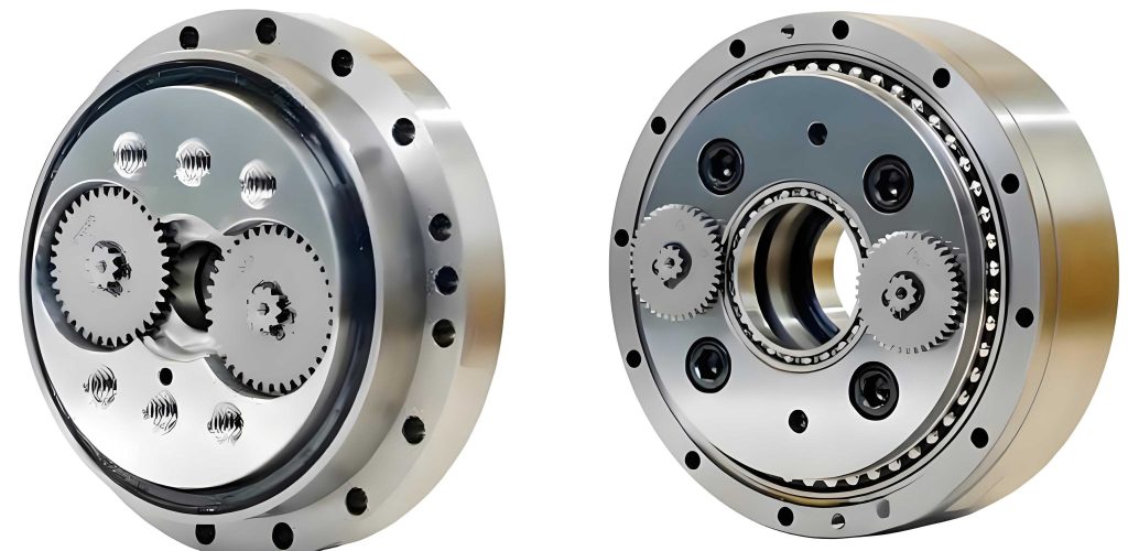
Transmission Principle and Structure
The beveloid rotary vector reducer transmission system comprises a two-stage gear train. The first stage is a standard involute planetary gear transmission, and the second stage is a beveloid gear small tooth difference transmission. The power flow is as follows: The input shaft, integrated with the sun gear (1), is driven by a motor. The sun gear meshes with multiple planetary gears (2), causing them to rotate on their own axes while revolving around the sun gear. Each planetary gear is rigidly connected to a crank shaft (3). The crank shaft drives the beveloid external gear (4), which is mounted on it via bearings. The beveloid external gear (4) meshes with the fixed beveloid internal gear (5). Due to the small difference in the number of teeth between gears (4) and (5), the beveloid external gear undergoes a slow reverse rotation relative to the crank arm’s revolution. This motion is extracted by the planet carrier (6), which serves as the output mechanism. Disc springs are incorporated between the beveloid external gear and the planet carrier to provide axial preload and compensate for potential axial play, ensuring meshing stability and minimal backlash. The overall transmission ratio of this rotary vector reducer is given by:
$$ i = 1 + \frac{z_2}{z_1} \cdot \frac{z_5}{z_5 – z_4} $$
where \( z_1 \) is the number of teeth on the first-stage sun gear, \( z_2 \) is the number of teeth on the planetary gears, \( z_4 \) is the number of teeth on the beveloid external gear, and \( z_5 \) is the number of teeth on the beveloid internal gear.
Dynamic Modeling of the System
Establishing an accurate dynamic model is the cornerstone for analyzing the performance of the beveloid rotary vector reducer. A lumped-parameter modeling approach, based on the Lagrangian equation, is employed to construct a bending-torsion-axial coupled dynamic model that accounts for the interaction between the two transmission stages. The model considers the following key components and factors:
- Components: Sun gear, planetary gears (typically three), planet carrier, crank shafts (three), beveloid external gears (two, often used in parallel for load sharing), and the beveloid internal gear (fixed to the housing).
- Stiffness Elements: Time-varying mesh stiffness of both the involute and beveloid gear pairs, radial and axial support stiffness of all bearings, and the axial stiffness of the disc spring assembly.
- Damping Elements: Mesh damping and support damping.
- Excitation Sources: Static transmission error (TE) and external load torques.
Coordinate systems are established at the geometric center of each component. The degrees of freedom (DOFs) considered for each component are chosen based on their force environment:
- Sun Gear & Planetary Gears (First Stage): Two translational DOFs (x, y) in the radial plane and one torsional DOF (u), as axial forces are negligible in this stage.
- Beveloid Gears (Second Stage): Two translational DOFs (x, y), one axial DOF (z), and one torsional DOF (u), as the beveloid mesh generates significant axial forces.
- Planet Carrier & Crank Shafts: Three translational DOFs (x, y, z) and one torsional DOF (u) to account for spatial motion.
The system’s kinetic energy (T), potential energy (U), and dissipative energy (R) are formulated. The mesh deformations (\(\sigma\)) and relative displacements at bearing supports are expressed in terms of the generalized coordinates (q). Applying the Lagrangian equation:
$$ \frac{d}{dt} \left( \frac{\partial L}{\partial \dot{q}} \right) – \frac{\partial L}{\partial q} + \frac{\partial R}{\partial \dot{q}} = F(t) $$
where \( L = T – U \), leads to the system’s equations of motion. These equations can be succinctly written in matrix form:
$$ \mathbf{M} \ddot{\mathbf{q}} + [\mathbf{C}_b + \mathbf{C}_r + \mathbf{C}_m(t)] \dot{\mathbf{q}} + [\mathbf{K}_b + \mathbf{K}_{dh} + \mathbf{K}_r + \mathbf{K}_m(t)] (\mathbf{q} + \mathbf{e}(t)) = \mathbf{F}(t) $$
Here, \(\mathbf{M}\) is the mass matrix; \(\mathbf{K}_b\), \(\mathbf{K}_r\), \(\mathbf{K}_{dh}\) are the stiffness matrices for bearings, the fixed ring gear support, and disc springs, respectively; \(\mathbf{K}_m(t)\) is the time-varying mesh stiffness matrix; \(\mathbf{C}_b\), \(\mathbf{C}_r\), \(\mathbf{C}_m(t)\) are the corresponding damping matrices; \(\mathbf{e}(t)\) is the static transmission error vector; and \(\mathbf{F}(t)\) is the external force vector.
System Parameters and Excitation Calculation
The analysis is performed on a prototype beveloid rotary vector reducer. Its key design parameters are summarized in the table below.
| Component | Parameter | Value | Unit |
|---|---|---|---|
| First Stage (Planetary) | Sun Gear Teeth (\(z_1\)) | 18 | – |
| Planet Gear Teeth (\(z_2\)) | 36 | – | |
| Module (\(m_n\)) | 1.25 | mm | |
| Pressure Angle (\(\alpha\)) | 20 | deg | |
| Mass of Sun Gear | 0.015 | kg | |
| Second Stage (Beveloid) | Internal Gear Teeth (\(z_5\)) | 78 | – |
| External Gear Teeth (\(z_4\)) | 80 | – | |
| Module (\(m_n\)) | 1.5 | mm | |
| Reference Cone Angle (\(\gamma\)) | 2.5 | deg | |
| Mass of Beveloid Internal Gear | 2.715 | kg | |
| General | Nominal Input Speed | 3000 | rpm |
| Rated Output Torque | 412 | Nm | |
| Disc Spring Stiffness (\(k_{dh}\)) | 4.5 × 10⁶ | N/m |
Stiffness and Damping Coefficients:
Bearing stiffness values are calculated based on empirical formulas. The time-varying mesh stiffness for the involute planetary stage is derived using potential energy methods, resulting in a periodic function:
$$ k_{msp}(t) = 2.64 \times 10^7 + 3.85 \times 10^6 \cos(2\pi f_{msp} t) \, \text{N/m} $$
where \( f_{msp} \) is the first-stage mesh frequency.
For the beveloid gear pair, due to the lack of a universal analytical formula, the mesh stiffness is determined using a combination of Finite Element Analysis (FEA) and curve fitting. The tangential mesh stiffness (\(k_{mtrg}\)) varies significantly throughout the mesh cycle and is approximated by a fitted function plus a harmonic component, while the axial mesh stiffness is related to it by the cone angle: \( k_{mzrg} = k_{mtrg} \tan \gamma \). Damping coefficients are typically estimated as a percentage of the critical damping.
Dynamic Response Analysis
Solving the system’s differential equations under rated operating conditions (3000 rpm input, 412 Nm output load) provides insights into the dynamic behavior of the beveloid rotary vector reducer.
Dynamic Meshing Forces
The dynamic meshing force in the first-stage sun-planet mesh and the second-stage beveloid gear mesh are extracted. Both forces exhibit periodic fluctuations. The fluctuation frequency for the planetary mesh corresponds precisely to its mesh frequency (\(f_{msp} = 888.9 \, \text{Hz}\)), and that for the beveloid mesh corresponds to its mesh frequency (\(f_{mrg} \approx 1876 \, \text{Hz}\)). The mean dynamic meshing force for the beveloid stage is approximately 3561 N, with a dynamic peak of around 3677 N, showing close agreement with the theoretical static force and confirming the model’s validity. The forces in the planetary stage are significantly lower, as expected for the high-speed, low-torque stage.
Vibration Response of Components
The vibration acceleration responses of key components, such as the fixed beveloid internal gear and the output planet carrier, are analyzed in both time and frequency domains. The fixed internal gear, due to its rigid connection to the housing, shows lower acceleration amplitudes compared to the planet carrier. The planet carrier’s response is more pronounced, especially in the radial directions. Frequency domain analysis (FFT) of these accelerations reveals the primary excitation sources. The spectrum for the beveloid internal gear is dominated by frequency components related to the second-stage meshing (\(f_{mrg}\) and its harmonics). In contrast, the spectrum for the planet carrier contains significant components from both the first-stage meshing (\(f_{msp}\)) and the second-stage meshing. This clearly demonstrates the coupling effect between the two stages; vibrations from the planetary stage are transmitted through the crank shafts and planet carrier to the output, influencing the overall dynamic performance of the rotary vector reducer. A system-level model is therefore indispensable.
Transmission Error Analysis and Parametric Study
Transmission error (TE), defined as the difference between the actual and ideal output position for a given input, is a critical measure of precision for the rotary vector reducer. The system’s TE is calculated from the dynamic model. Due to system damping, the TE transient response decays, settling to a steady-state fluctuation around a mean value. Parametric studies investigate the influence of key operating and design parameters on TE.
Effect of Load Torque
Simulations are conducted with varying output load torques (T). The results show that both the mean value and the peak-to-peak value of the steady-state TE increase significantly with load. This is attributed to the increased elastic deflections of gear teeth, shafts, and bearings under higher loads, which directly impact the kinematic accuracy of the rotary vector reducer.
| Load Torque (Nm) | TE Peak-to-Peak (arcmin) | TE Mean (arcmin) |
|---|---|---|
| 0.1 (No-load) | 0.093 | 0.007 |
| 100 | 0.102 | 1.345 |
| 200 | 0.112 | 2.691 |
| 300 | 0.123 | 4.036 |
| 412 (Rated) | 0.134 | 5.512 |
Effect of Disc Spring Initial Compression
The disc spring’s initial compression (\(\delta\)) determines its preload. Analysis shows that this parameter has a pronounced effect on the dynamic fluctuation (peak-to-peak) of the TE, while its effect on the mean TE is relatively minor. A larger initial compression increases the peak-to-peak TE. This is because excessive preload can alter the effective mesh conditions and potentially introduce additional stiffness nonlinearities. Therefore, selecting an optimal initial compression is a critical design trade-off for the beveloid rotary vector reducer, balancing backlash elimination against dynamic excitation.
| Initial Compression \(\delta\) (mm) | TE Peak-to-Peak (arcmin) | TE Mean (arcmin) |
|---|---|---|
| 0.1 | 0.180 | 5.566 |
| 0.5 | 0.236 | 5.596 |
| 1.0 | 0.353 | 5.676 |
| 1.5 | 0.489 | 5.726 |
| 2.0 | 0.526 | 5.747 |
Effect of Input Speed
Varying the input speed (\(\omega\)) shows that it has a moderate influence on the peak-to-peak TE, but a negligible effect on the mean TE value. The changes in peak-to-peak TE are related to the shifting of excitation frequencies relative to the system’s natural frequencies. The mean TE remains stable because it is primarily determined by the load-dependent elastic deformations, which are constant for a given load in this study.
| Input Speed (rpm) | TE Peak-to-Peak (arcmin) | TE Mean (arcmin) |
|---|---|---|
| 500 | 0.108 | 5.544 |
| 1000 | 0.112 | 5.543 |
| 1500 | 0.130 | 5.544 |
| 2000 | 0.127 | 5.545 |
| 2500 | 0.158 | 5.544 |
Conclusion
This work presents a comprehensive dynamic analysis of the beveloid rotary vector reducer. A coupled bending-torsion-axial dynamic model was successfully established using the Lagrangian method, incorporating the interactions between the two transmission stages, time-varying mesh stiffness, bearing compliance, disc spring effects, damping, and transmission error excitation. Analysis of a prototype model under rated conditions validated the model and revealed key dynamic characteristics. The dynamic meshing forces exhibit fluctuations at their respective mesh frequencies. Vibration analysis confirmed that the dynamics of the first planetary stage significantly influence the output response, underscoring the necessity of a coupled system model for the rotary vector reducer. Transmission error studies identified load torque and disc spring preload as critical parameters affecting precision. Load torque dominantly influences the mean TE, while disc spring initial compression has a major impact on the dynamic fluctuation (peak-to-peak) of the TE. Input speed has a comparatively smaller effect. These findings provide a vital theoretical foundation for the dynamic design, performance prediction, and parameter optimization of high-precision beveloid rotary vector reducers.