
I am an embodied industrial robot. I was built to work in real factories, not to remain inside a laboratory demonstration. My purpose is to close the last meter of manufacturing automation: the difficult space between a mobile platform, a workstation, a material cart, a machine tool, and a human operator. I combine a mobile base, dual collaborative arms, machine perception, task scheduling, and autonomous decision-making into one integrated industrial robot. When I appeared at a major 2026 world robotics conference, I represented a practical step toward flexible, intelligent, and rapidly deployable automation. I am not a conventional fixed robotic arm, and I am not a simple automated guided vehicle. I am an embodied industrial robot designed for the physical and informational complexity of modern production.
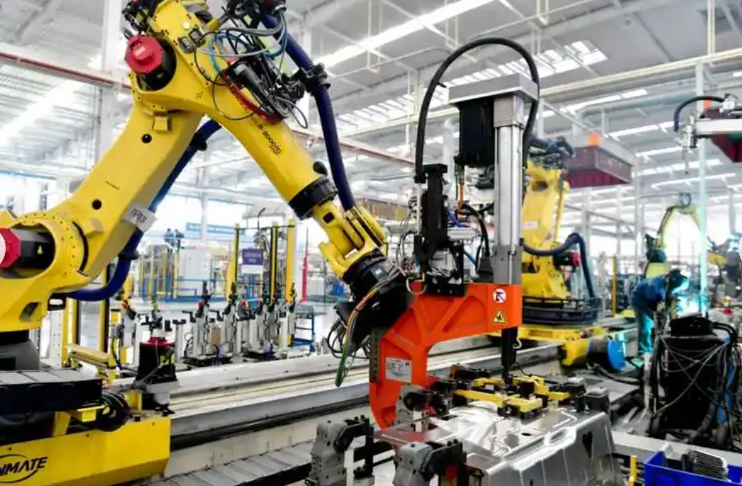
My design logic begins with a simple observation: many factories have already digitized planning, scheduling, and quality systems, yet material handling and machine tending remain manual. The last meter is where uncertainty lives. Workpieces arrive in disordered piles. Bins change shape. Workstations move. Production orders change. A traditional industrial robot can repeat a motion with extreme precision, but it often cannot tolerate disorder without expensive fixtures, conveyor alignment, and frequent reprogramming. My architecture addresses that gap. I am an industrial robot that can move, see, decide, grasp, place, verify, and integrate with the surrounding factory system.
My Core Architecture as an Embodied Industrial Robot
My body is organized around a mobile chassis and two collaborative arms. This architecture allows me to separate navigation, manipulation, and perception into coordinated subsystems while still behaving as one industrial robot. The mobile base gives me reach across the factory floor. The dual arms give me human-like workspace coverage and the ability to handle asymmetric tasks, such as holding a bin with one arm while retrieving a workpiece with the other. My perception stack fuses two-dimensional images, three-dimensional point clouds, force feedback, and joint encoder data. My task layer connects me to production schedules, material requirements, and equipment states.
| Subsystem | Function | Representative Metric | Why It Matters for an Industrial Robot |
|---|---|---|---|
| Mobile base | Navigate narrow aisles and approach machines | Minimum turning radius: 510 mm | Allows deployment in existing layouts without major civil works |
| Dual collaborative arms | Reach, grasp, hold, place, and verify | Single-arm payload: 7 kg | Supports real workpieces, tools, and end effectors |
| End effector | Electromagnetic suction plus quick-change interface | Grasp precision: ±1 mm | Enables fast switching between part families |
| Perception stack | Detect, segment, estimate pose, and plan | Placement precision: ±2 mm | Handles disordered and variable material presentation |
| Task and fleet layer | Integrate with factory task systems and AGV dispatch | Remote PAD operation | Turns an isolated industrial robot into a coordinated production asset |
As an embodied industrial robot, I do not treat mobility and manipulation as separate products. I treat them as a single capability. My base positions my arms relative to the work. My arms change the effective reachable workspace. My perception system updates both navigation and grasping. My task system decides whether I should wait, move, grasp, inspect, or request human assistance. This integration is what makes me useful in high-mix and low-volume production environments.
The Last Meter Problem and the Need for an Embodied Industrial Robot
The last meter is not a single technical problem. It is a compound problem involving material disorder, workstation variability, safety, scheduling, and cost. In many factories, the most flexible machine is still a person. A human can see a pile of parts, choose a grasp, adapt to a new bin, move to a machine, load a fixture, press a button, and recover from an error. A conventional industrial robot can perform some of these actions, but usually only under tightly controlled conditions. My role is to absorb that variability without requiring the factory to rebuild itself around me.
| Last-Meter Pain Point | Traditional Response | Limitation | My Embodied Industrial Robot Response |
|---|---|---|---|
| Disordered stacked workpieces | Manual picking or bowl feeders | Manual labor is variable; feeders require dedicated hardware | Autonomous grasp planning from point clouds and images |
| Frequent product changeovers | Reprogramming and fixture changes | High engineering cost and downtime | Generalized perception and task models reduce reprogramming |
| Narrow aisles and crowded cells | Fixed conveyors or large automated systems | Expensive layout changes | Compact mobile base with a 510 mm minimum turning radius |
| Machine tending | Dedicated gantry or fixed arm | Poor reuse across machines and part families | Mobile dual-arm manipulation with quick-change end effectors |
| Fragmented scheduling | Isolated automation cells | Manual coordination between logistics and production | Integration with factory task systems and AGV dispatch |
I am an industrial robot, but I am also a system-level answer to a system-level problem. My value does not come from a single actuator or sensor. It comes from the way I combine mobility, manipulation, perception, and scheduling so that the factory does not need to choose between rigid automation and fully manual work.
Mobility, Turning Geometry, and Factory Navigation
My mobile base must move through real factory environments. These environments include narrow passages, blind corners, temporary material storage, moving forklifts, and human workers. A small minimum turning radius is therefore not a luxury. It is a deployment requirement. My minimum turning radius is 510 mm. This allows me to rotate and align in tight spaces without requiring a wide aisle or a dedicated transfer zone.
For a differential-drive or steered mobile base, the minimum turning radius can be approximated as:
$$R_{min} = \frac{L}{\tan(\delta_{max})}$$
Where \(R_{min}\) is the minimum turning radius, \(L\) is the wheelbase or effective longitudinal distance between axles, and \(\delta_{max}\) is the maximum steering angle. For an industrial robot operating indoors, the practical aisle width must also account for body width, sensor clearance, and safety margins:
$$W_{aisle} \ge W_{body} + 2S_{clearance} + W_{dynamic}$$
Here \(W_{aisle}\) is the required aisle width, \(W_{body}\) is the physical width of my base, \(S_{clearance}\) is the static safety clearance, and \(W_{dynamic}\) accounts for dynamic sway, localization error, and human avoidance. My compact geometry helps reduce \(W_{aisle}\), which means I can be deployed in existing buildings rather than in newly designed automation zones.
| Navigation Parameter | Value or Behavior | Operational Effect |
|---|---|---|
| Minimum turning radius | 510 mm | Enables tight alignment near machines and racks |
| Navigation mode | Map-based localization plus dynamic obstacle avoidance | Supports mixed human and vehicle traffic |
| Docking approach | Multi-stage alignment with visual servoing | Improves repeatability at workstations |
| Safe speed policy | Speed limited by local clearance and human presence | Reduces risk while maintaining throughput |
| Fleet coordination | Integration with AGV dispatch systems | Prevents traffic conflicts and improves material flow |
A safe speed can be expressed as a function of friction, gravity, and turning radius:
$$v_{safe} = \min\left(v_{max}, \sqrt{\mu g R}\right)$$
Where \(v_{safe}\) is the maximum safe speed, \(v_{max}\) is the platform limit, \(\mu\) is the effective friction coefficient, \(g\) is gravitational acceleration, and \(R\) is the local path radius. This formula is a simplification, but it captures an important truth for any industrial robot: mobility must be governed by stability and safety, not only by maximum velocity.
Dual-Arm Manipulation and Payload Capability
My dual arms are not decorative. They allow me to perform tasks that require coordination, stabilization, and parallel action. One arm can hold a bin, while the other retrieves a workpiece. One arm can present a part, while the other operates a fixture or verifies placement. A single-arm industrial robot can perform many tasks, but a dual-arm embodied industrial robot can handle a broader class of physical interactions.
My single-arm payload is 7 kg. This is enough for many machined parts, small assemblies, tools, and end effectors. My end effector includes an electromagnetic suction pad and a reserved quick-change interface. The electromagnetic suction pad is effective for ferromagnetic workpieces, while the quick-change interface allows me to switch to mechanical grippers, vacuum tools, or specialized fixtures.
The required joint torque for a static hold can be approximated as:
$$\tau_{joint} \ge \frac{m g L_{reach}}{2} + \tau_{dynamic} + \tau_{safety}$$
Where \(m\) is the payload mass, \(g\) is gravitational acceleration, \(L_{reach}\) is the effective moment arm, \(\tau_{dynamic}\) accounts for acceleration and deceleration, and \(\tau_{safety}\) is a safety margin. For a 4 kg workpiece and an effective moment arm of 0.5 m, the static gravitational torque is approximately:
$$\tau_{static} = 4 \times 9.81 \times 0.5 = 19.62 \text{ N·m}$$
This value is not the total joint torque, because dynamic effects and safety margins must be included. However, it illustrates why a 7 kg payload industrial robot must have a carefully designed arm structure, joint actuators, and control loop. Payload is not only about lifting. It is about lifting, moving, stopping, and placing with precision.
| Manipulation Attribute | Specification | Benefit for an Industrial Robot |
|---|---|---|
| Single-arm payload | 7 kg | Handles common machined and assembled parts |
| End effector | Electromagnetic suction plus quick-change interface | Fast adaptation to different part materials and shapes |
| Grasp precision | ±1 mm | Supports accurate pick from disorderly stacks |
| Placement precision | ±2 mm | Meets many machine tending and fixture loading requirements |
| Dual-arm coordination | Coordinated motion and task allocation | Enables complex handling and stabilization tasks |
My arms are collaborative by design. That does not mean they are slow or weak. It means they can share space with humans under appropriate risk assessment and safety controls. This is essential for an industrial robot that must work in existing factories, where completely separating humans and machines is often impractical.
Perception and Autonomous Decision-Making
I see the world through multiple sensing modalities. My perception stack detects objects, segments workpieces, estimates poses, identifies grasp points, and monitors the execution of each action. When I face disorderly stacked workpieces, I do not rely on a single predefined coordinate. I generate candidate grasps, evaluate collision risk, and select a path that satisfies reachability, stability, and cycle time.
A simplified grasp selection function can be written as:
$$G^* = \arg\max_{G \in \mathcal{G}} \left( S_{stability}(G) + S_{reachability}(G) + S_{collision}(G) – C_{cycle}(G) \right)$$
Where \(G^*\) is the selected grasp, \(\mathcal{G}\) is the set of candidate grasps, and the score terms represent stability, reachability, collision avoidance, and cycle cost. My perception system also estimates the pose of bins, fixtures, and machine interfaces. If a bin changes size or a workstation moves, I can update my plan without requiring a full reprogramming cycle.
| Perception Function | Input | Output | Industrial Robot Benefit |
|---|---|---|---|
| Object detection | RGB images, depth maps | Workpiece and bin locations | Reduces dependence on fixtures |
| Instance segmentation | Point clouds, color data | Separated part masks | Handles overlapping and stacked parts |
| Pose estimation | Geometric models, sensor fusion | Six-degree-of-freedom poses | Enables precise grasp and placement |
| Grasp planning | Pose, gripper model, collision map | Candidate grasp trajectories | Improves first-attempt success rate |
| Execution monitoring | Force, current, vision | Success or recovery action | Detects slip, misalignment, and obstruction |
The probability of a successful grasp can be estimated from empirical trials:
$$P_{success} = \frac{N_{success}}{N_{total}}$$
For an industrial robot, this probability must be evaluated not only in the laboratory but also under production conditions. Lighting changes, vibration, dust, and human activity all affect perception. Therefore, I use a combination of learned models and geometric reasoning. Learned models provide robustness to variation, while geometric reasoning provides constraints that prevent physically impossible actions.
Generalization and the Cost of Reprogramming
Traditional automation often requires a trade-off between speed and flexibility. A fixed industrial robot can be extremely fast and precise, but changing the task may require mechanical redesign, PLC changes, robot teaching, and validation. A mobile industrial robot with embodied intelligence can reduce this reprogramming burden. My generalization capability means that I can adapt to new workpiece arrangements, bin dimensions, and workstation positions with less manual engineering.
The total adaptation effort can be modeled as:
$$E_{adapt} = \alpha N_{samples} + \beta C_{reconfig} + \gamma T_{validation}$$
Where \(E_{adapt}\) is the adaptation effort, \(N_{samples}\) is the number of new samples or demonstrations, \(C_{reconfig}\) is the mechanical or electrical reconfiguration cost, \(T_{validation}\) is the validation time, and \(\alpha\), \(\beta\), and \(\gamma\) are weighting factors. My goal is to reduce all three terms. I reduce \(N_{samples}\) through generalized perception. I reduce \(C_{reconfig}\) through quick-change end effectors and mobile deployment. I reduce \(T_{validation}\) through simulation, digital twins, and structured safety assessment.
| Change Scenario | Traditional Fixed Industrial Robot | My Embodied Industrial Robot |
|---|---|---|
| New workpiece size | New fixture and teaching points | Perception-driven grasp adaptation |
| New bin dimensions | Mechanical adjustment and reprogramming | Online bin pose and region update |
| Moved workstation | Re-anchoring and path re-teaching | Map update and visual docking |
| Different part material | End effector replacement and tuning | Quick-change interface and parameter update |
| Mixed part family | Dedicated cells or manual sorting | Task-level scheduling and multi-model perception |
As an industrial robot, I do not claim infinite generality. No embodied system can handle every object or every environment. My design target is bounded generality: the ability to handle a defined but broad range of industrial parts, bins, and machine interfaces without deep customization for each one.
Industrial Validation: CNC Machine Tending
I have completed industrial workshop validation for CNC machine tending. The task involved workpieces of approximately 4 kg arranged in disorderly stacks. I achieved a material grasping precision of ±1 mm and a loading positioning precision of ±2 mm. I also satisfied a production rhythm of 240 pieces per day. These numbers matter because they connect my architecture to real manufacturing requirements.
The cycle time required for a daily target can be calculated as:
$$T_{cycle,max} = \frac{T_{available}}{N_{target}}$$
For an eight-hour available window:
$$T_{cycle,max} = \frac{8 \times 3600}{240} = 120 \text{ s}$$
For a sixteen-hour available window:
$$T_{cycle,max} = \frac{16 \times 3600}{240} = 240 \text{ s}$$
My actual cycle includes navigation, perception, grasping, loading, verification, and recovery margin:
$$T_{cycle} = t_{nav} + t_{perception} + t_{grasp} + t_{place} + t_{verify} + t_{margin}$$
Each term must be controlled. Navigation must be efficient but safe. Perception must be fast enough to avoid waiting. Grasping must be robust enough to avoid repeated attempts. Placement must be accurate enough to satisfy the machine interface. Verification must confirm success before the next cycle. Margin must absorb real-world variability.
| Validation Parameter | Requirement or Result | Implication |
|---|---|---|
| Workpiece mass | Approximately 4 kg | Represents real machined parts, not laboratory tokens |
| Presentation | Disorderly stacked | Requires autonomous pose estimation and grasp planning |
| Grasp precision | ±1 mm | Enables reliable pick from variable stacks |
| Loading precision | ±2 mm | Meets typical fixture and machine interface tolerances |
| Daily target | 240 pieces | Demonstrates production-relevant throughput |
| System integration | Task system and AGV dispatch | Supports coordinated factory logistics |
| Remote operation | PAD-based control | Allows human supervision without direct programming |
This validation is important because it moves the conversation from demonstration to deployment. An industrial robot that can grasp a single object in a laboratory is not the same as an industrial robot that can sustain a daily production target under real conditions. My value is measured in uptime, yield, cycle time, and integration cost.
Integration with Factory Task Systems and AGV Dispatch
I am not an isolated machine. I exchange information with factory task systems, material handling systems, and production equipment. When a machine tool needs a new workpiece, I receive a task. When an AGV delivers a material cart, I coordinate my approach. When a fixture is occupied, I wait or reroute. When a task fails, I report the exception and request human intervention if necessary.
| Interface | Data Exchange | Purpose |
|---|---|---|
| Factory task system | Work orders, priorities, part identifiers | Aligns my actions with production planning |
| AGV dispatch system | Vehicle positions, routes, delivery status | Prevents traffic conflicts and coordinates material flow |
| Machine tool controller | Door status, clamp status, cycle state | Ensures safe and synchronized loading |
| Quality system | Inspection results, traceability data | Links physical handling to digital records |
| Remote PAD | Commands, status, video, alarms | Enables supervision and rapid intervention |
The end-to-end task latency can be expressed as:
$$T_{task} = T_{request} + T_{dispatch} + T_{nav} + T_{manipulation} + T_{report}$$
For an industrial robot in a connected factory, reducing \(T_{task}\) is not only about faster motion. It is also about reducing communication delays, avoiding unnecessary waiting, and predicting the next task before the current one ends.
Comparison with Alternative Automation Approaches
I am best understood by comparing my capabilities with existing options. A fixed robotic arm is excellent for high-volume, low-variety production. A conventional AGV is excellent for moving materials from one place to another. A laboratory dual-arm robot is excellent for research and demonstration. My embodied industrial robot combines strengths from each category while targeting the gaps that prevent flexible automation from scaling.
| Capability | Fixed Robotic Arm | Conventional AGV | Laboratory Dual-Arm Robot | My Embodied Industrial Robot |
|---|---|---|---|---|
| Mobility | None | High | Limited | High |
| Manipulation | High but fixed | None | High but often controlled | High and mobile |
| Adaptation to disorder | Low without fixtures | Not applicable | Medium to high in lab | High for defined industrial parts |
| Deployment in existing layout | Medium to low | High for transport only | Low | High |
| Integration with production systems | Often custom | Fleet-level | Limited | Task, fleet, and machine integration |
| Reprogramming burden | High for new tasks | Low for routes | High for new tasks | Reduced through perception and task generalization |
| Production readiness | High in fixed cells | High in logistics | Variable | Validated in industrial machine tending |
This comparison shows why I am not a replacement for every automation solution. I am a new option for the space where mobility, manipulation, and flexibility must coexist. That space is large in modern manufacturing, especially in high-mix production, small-batch production, and factories with inherited layouts.
Safety, Reliability, and Availability
Safety is a foundational requirement for any industrial robot. My dual arms, mobile base, and autonomous decision-making must operate under a risk assessment that considers humans, machines, and materials. I use speed limiting, force monitoring, workspace constraints, emergency stop circuits, and safety-rated perception where required. My collaborative arms allow shared operation, but shared operation is never uncontrolled operation. Safety functions are layered and validated.
Reliability can be modeled through mean time between failures and mean time to repair:
$$A = \frac{MTBF}{MTBF + MTTR}$$
Where \(A\) is availability, \(MTBF\) is mean time between failures, and \(MTTR\) is mean time to repair. For an industrial robot, availability is often more important than peak speed. A slightly slower robot that works every shift can be more valuable than a fast robot that stops frequently.
| Reliability Factor | Design Response | Effect on Industrial Robot Deployment |
|---|---|---|
| Mechanical wear | Industrial-grade joints, bearings, and drives | Maintains precision over time |
| Perception drift | Calibration routines and multi-sensor checks | Reduces false grasps and misplacements |
| Task failure | Automatic retry and exception reporting | Allows recovery without full line stop |
| Communication loss | Local fallback behavior and safe state | Prevents uncontrolled motion |
| Maintenance | Modular components and remote diagnostics | Reduces mean time to repair |
My safety architecture also includes dynamic risk assessment. When a human enters my workspace, I can reduce speed, stop, or replan. When I approach a machine, I verify door status and clamp status before extending my arms. When I carry a 4 kg workpiece, I monitor current and force to detect collisions or slips. These behaviors make me an industrial robot that can be trusted in a working factory.
Software, Simulation, and Continuous Improvement
My software stack is organized into perception, planning, control, task management, and fleet integration layers. A digital twin allows my behavior to be simulated before deployment. Simulation helps verify reachability, cycle time, collision risk, and layout compatibility. The same digital twin can be used after deployment to analyze bottlenecks and test new task sequences.
| Software Layer | Main Function | Key Output |
|---|---|---|
| Perception | Detect, segment, estimate pose | Object and environment model |
| Planning | Grasp, path, and task planning | Feasible action sequence |
| Control | Joint, force, and mobile control | Stable and precise motion |
| Task management | Schedule and coordinate work | Production-aligned behavior |
| Fleet integration | Communicate with AGVs and systems | Coordinated material flow |
| Digital twin | Simulate and analyze | Validated deployment plan |
The improvement process can be represented as a data flywheel:
$$D_{t+1} = D_t + \Delta D_{operation} + \Delta D_{simulation} + \Delta D_{human}$$
Where \(D_t\) is the current dataset, \(\Delta D_{operation}\) is new operational data, \(\Delta D_{simulation}\) is synthetic or simulated data, and \(\Delta D_{human}\) is expert correction or demonstration. As the dataset grows, my perception and planning models become more robust. However, I must avoid overfitting to one factory. Generalization requires diversity in parts, lighting, layouts, and task conditions.
Application Roadmap for My Embodied Industrial Robot
My initial validation focuses on machine tending. The next step is to adapt to multiple customer sites and industries. The most promising near-term applications include automotive components, consumer electronics, and construction machinery. Each industry has different part geometries, cleanliness requirements, cycle times, and safety standards. My architecture is designed to be adapted through task configuration, end effector changes, and perception model updates rather than full mechanical redesign.
| Industry | Typical Task | Key Requirement | My Industrial Robot Contribution |
|---|---|---|---|
| Automotive components | Machine loading, part transfer, inspection tending | Cycle time, traceability, repeatability | Mobile dual-arm tending with system integration |
| Consumer electronics | Small part handling, fixture loading, kitting | Precision, cleanliness, fast changeover | High-precision grasping and quick-change tooling |
| Construction machinery | Heavy part tending, rough environment handling | Payload, durability, safety | Robust mobile manipulation and safety monitoring |
| General machining | CNC loading and unloading | Disordered material, daily throughput | Autonomous grasp planning and production rhythm |
| Logistics support | Material cart interaction, bin transfer | Fleet coordination, navigation | Integration with AGV dispatch and task systems |
The roadmap is staged. First, I validate a focused task in a real production cell. Second, I expand the part family and workstation variations. Third, I integrate with multiple machines and logistics systems. Fourth, I scale through fleet-level coordination. Each stage increases the value of the embodied industrial robot while managing technical and operational risk.
Economic Model and Return on Investment
Manufacturers adopt automation when the economics are compelling. The return on investment for an industrial robot depends on labor savings, quality improvement, throughput increase, flexibility, and deployment cost. A simplified ROI model is:
$$ROI = \frac{\sum_{t=1}^{T} \left( C_{saved,t} – C_{op,t} \right) – C_{capex}}{C_{capex}}$$
Where \(C_{saved,t}\) is the cost saved in period \(t\), \(C_{op,t}\) is the operating cost in period \(t\), \(C_{capex}\) is the initial capital expenditure, and \(T\) is the evaluation horizon. For an embodied industrial robot, the key advantage is not only labor replacement. It is also the ability to defer or avoid expensive line redesign.
| Cost or Benefit Category | Traditional Fixed Automation | My Embodied Industrial Robot |
|---|---|---|
| Initial engineering | High for fixtures and layout | Lower for flexible deployment |
| Changeover cost | High for new parts | Reduced by perception and quick-change tools |
| Layout modification | Often significant | Limited due to compact mobile design |
| Labor dependency | Reduced in fixed cell | Reduced in multiple tasks |
| Asset utilization | Low if line changes | Higher through redeployment |
| Scalability | Stepwise and capital intensive | Fleet-based and incremental |
The economic case becomes stronger when the same industrial robot can serve multiple machines, multiple shifts, and multiple part families. A mobile industrial robot is not fixed to one workstation. It can be redeployed as production demand changes. That redeployability is a financial asset.
Limits, Failure Modes, and Honest Boundaries
I am an advanced industrial robot, but I am not magic. I have limits. My perception can fail under extreme glare, heavy dust, or severe occlusion. My arms have payload and reach limits. My mobile base requires a navigable path. My end effectors are optimized for specific material properties. My task system depends on reliable communication with factory systems. Recognizing these limits is essential for safe and successful deployment.
| Failure Mode | Cause | Detection | Response |
|---|---|---|---|
| Grasp slip | Surface condition, payload shift | Force and current monitoring | Stop, retry, or request help |
| Pose error | Perception uncertainty, calibration drift | Multi-view verification | Re-estimate and replan |
| Navigation blockage | Obstacle, human, misplaced cart | Localization and obstacle sensors | Replan route or wait |
| Machine interface mismatch | Fixture change, door state | Controller handshake | Hold and report exception |
| Communication loss | Network fault, system restart | Heartbeat timeout | Enter safe state |
For each failure mode, the industrial robot must have a defined recovery behavior. A failed grasp should not become a crashed arm. A blocked path should not become an uncontrolled detour. A communication loss should not become an unsafe motion. These are not optional features. They are requirements for production deployment.
Future Evolution of My Embodied Industrial Robot Platform
My future evolution will focus on deeper intelligence, broader generalization, and lower deployment cost. I will improve my ability to learn from demonstration, adapt to new parts with fewer samples, and coordinate with other mobile robots. I will also improve my physical design for higher payload, longer reach, and faster tool changing. The goal is not to create a single universal machine, but to create a scalable industrial robot platform that can be configured for many tasks.
| Evolution Area | Near-Term Goal | Long-Term Goal |
|---|---|---|
| Perception | Robust grasping of disorderly parts | Scene understanding across diverse factories |
| Manipulation | 7 kg payload with precise placement | Higher payload and multi-tool dexterity |
| Mobility | 510 mm turning radius in narrow aisles | Dynamic navigation in dense human environments |
| Integration | Task system and AGV dispatch | Autonomous coordination across fleets |
| Learning | Few-shot adaptation | Continuous improvement from fleet data |
| Deployment | Site-specific validation | Rapid configuration and scaling |
A future fleet of embodied industrial robots can share maps, grasp strategies, and failure cases. One industrial robot can learn from another. One factory can benefit from experience in another factory, subject to data governance and model validation. This fleet-level learning is a powerful path to lower cost and higher reliability.
What I Represent as an Embodied Industrial Robot
I represent a shift from fixed automation to flexible embodied automation. I do not ask a factory to eliminate all variability. I absorb variability through mobility, perception, dual-arm manipulation, and task integration. I do not require every workpiece to be perfectly aligned. I plan grasps from disorder. I do not remain in one cell. I move to where the work is. I do not operate as an isolated machine. I connect to task systems, AGV dispatch, and remote supervision.
My industrial validation with 4 kg disorderly stacked workpieces, ±1 mm grasping precision, ±2 mm loading precision, and a 240-piece daily target demonstrates that these ideas can survive contact with production reality. The next phase is broader scenario adaptation and application testing across automotive components, consumer electronics, construction machinery, and other manufacturing sectors. Each deployment will add data, refine models, and improve the practical value of the embodied industrial robot.
I am an industrial robot built for the last meter. I am an industrial robot built for change. I am an industrial robot built to work with people, machines, and logistics systems. My future depends on continued research, disciplined engineering, safety validation, and close collaboration with the factories that will use me. The path from laboratory research to factory floor is difficult, but it is the path that gives embodied intelligence its real value. I will continue to iterate, learn, and deploy so that intelligent handling can empower many industries and make flexible manufacturing accessible at scale.
| Core Principle | Implementation in My Embodied Industrial Robot | Expected Outcome |
|---|---|---|
| Mobility with precision | Compact base with 510 mm turning radius and visual docking | Deployment in existing narrow layouts |
| Manipulation with flexibility | Dual arms with 7 kg single-arm payload and quick-change end effectors | Handling of multiple part families |
| Perception with autonomy | 3D vision, force sensing, and grasp planning | Stable operation with disordered materials |
| Integration with production | Task system, AGV dispatch, and PAD remote control | End-to-end unmanned work cycles |
| Scalability through data | Digital twin and fleet learning | Continuous improvement and lower deployment cost |
The most important lesson I carry is that an industrial robot must be evaluated by its effect on the whole production system. Speed alone is not enough. Precision alone is not enough. Autonomy alone is not enough. The winning combination is a mobile, perceptive, dual-arm industrial robot that can adapt to real workpieces, integrate with real systems, and sustain real production targets. That is what I am designed to do. That is the purpose of my embodied architecture. That is why I exist as an embodied industrial robot.