
As a critical component in precision heavy-duty transmission systems, such as industrial robot joints, radar, and CNC machine tools, the rotary vector reducer has garnered significant attention due to its advantages of high reduction ratio, compact size, high efficiency, and strong load-bearing capacity. In this article, I will delve into the dynamic meshing process and contact fatigue strength design of the rotary vector reducer, employing finite element methods to simulate and analyze its performance. The rotary vector reducer, often abbreviated as RV reducer, is a closed differential gear train that combines a high-speed stage of involute planetary gear transmission with a low-speed stage of cycloid-pin gear planetary transmission. This unique configuration makes the rotary vector reducer indispensable in applications requiring precise motion control and durability.
The primary objective of this study is to calculate the contact fatigue strength of the cycloid gear tooth surface in the rotary vector reducer. To achieve this, I analyze the dynamic meshing force process and the mechanism of contact fatigue initiation. By leveraging finite element software, I establish a detailed model of the cycloid-pin gear transmission, incorporating multi-point constraint equations to simulate bearing connections and rigid beam elements in a truss configuration to represent the planetary frame. Through dynamic simulation, I obtain the curve of maximum contact stress on the cycloid gear tooth surface as a function of the crankshaft rotation angle, which allows for an estimation of the contact fatigue life. The results demonstrate the feasibility of this finite element modeling approach for the rotary vector reducer, highlighting the impact of cycloid gear spoke deformation on contact stress and verifying the simulation error of bearing modeling. The estimated contact fatigue life approaches infinite life, underscoring the robustness of the rotary vector reducer design.
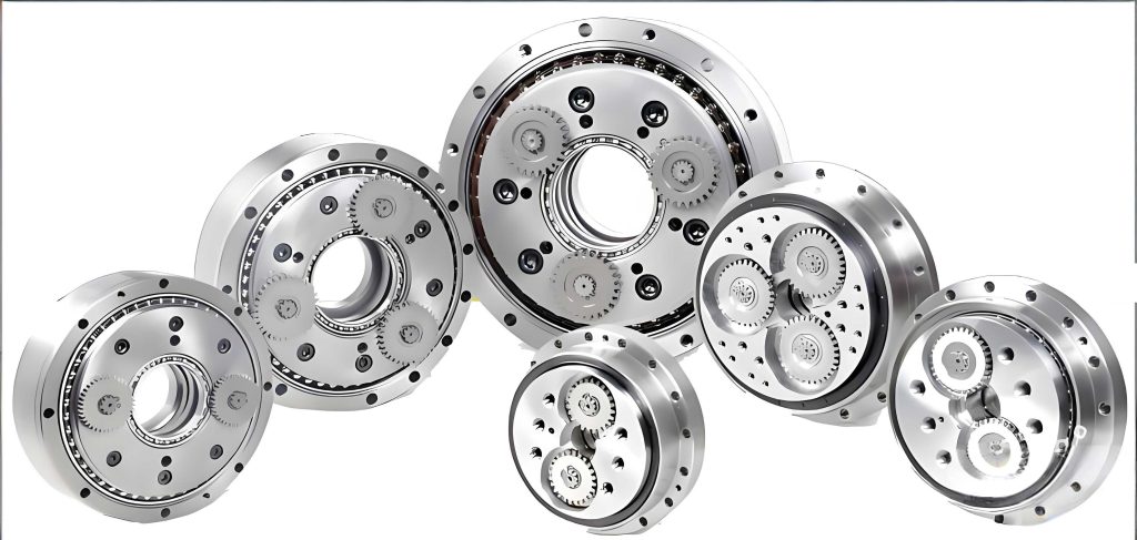
To understand the operational principles of the rotary vector reducer, consider its transmission mechanism. The rotary vector reducer consists of two main stages: a high-speed stage based on a K-H type involute planetary gear train and a low-speed stage based on a K-H-V type cycloid-pin gear planetary transmission. When the motor drives the central gear in a clockwise rotation, with the pin gear housing fixed and the planetary frame as the output, the central gear’s motion causes the planetary gears to rotate both on their own axes and around the central axis, achieving the first stage of speed reduction. The planetary gears are fixed to the crankshafts, which transfer motion to the low-speed stage. The crankshafts rotate counterclockwise, driving the cycloid gears to revolve counterclockwise. Due to the meshing constraints imposed by the pins, the cycloid gears also rotate clockwise on their own axes while revolving. This self-rotation of the cycloid gears drives the crankshafts to revolve clockwise, which in turn rotates the planetary frame clockwise, resulting in the second stage of speed reduction. This dual-stage mechanism is what gives the rotary vector reducer its high reduction ratio and efficiency.
The relationship between the crankshaft and pin gear housing angles is crucial for dynamic analysis. Based on planetary gear train theory, when the pin gear housing is fixed and the planetary frame is the output, the transmission ratio of the rotary vector reducer can be derived. Let \( \theta_1 \) be the rotation angle of the central gear, \( \theta_5 \) be the rotation angle of the planetary frame, \( z_1 \) be the number of teeth on the central gear, \( z_2 \) be the number of teeth on the planetary gear, and \( z_6 \) be the number of pins. The transmission ratio is given by:
$$ i_{15} = 1 + \frac{z_2}{z_1} z_6 = \frac{\theta_1}{\theta_5} $$
Alternatively, when the planetary frame is fixed and the pin gear housing is the output, the transmission ratio is:
$$ i_{16} = \frac{z_2}{z_1} z_6 = \frac{\theta_1}{\theta_6} $$
where \( \theta_6 \) is the rotation angle of the pin gear housing. For the high-speed stage, the transmission ratio between the central gear and planetary gear is:
$$ i_{12} = \frac{z_2}{z_1} = \frac{\theta_1}{\theta_2} $$
with \( \theta_2 \) as the rotation angle of the planetary gear. Since the planetary gear is fixed to the crankshaft, \( \theta_2 = \theta_3 \), where \( \theta_3 \) is the crankshaft angle. Substituting into the above equations, the relationship between the crankshaft and pin gear housing angles for the rotary vector reducer is:
$$ \theta_6 = \frac{\theta_3}{z_6} $$
This equation is fundamental for simulating the dynamic meshing process of the rotary vector reducer.
Analyzing the dynamic meshing process of the cycloid-pin gear transmission in the rotary vector reducer involves examining how the cycloid gear teeth engage with the pins over time. In this study, I consider the working mode where the planetary frame is fixed, the crankshaft serves as the input, and the pin gear housing is the output. As the crankshaft rotates, the cycloid gear undergoes translational motion without self-rotation. For instance, as a cycloid gear tooth engages with a pin, the pin rolls along the tooth profile from the entry point to the exit point. The tooth profile can be divided into a load-bearing surface and a non-load-bearing surface. During one complete rotation of the crankshaft, the cycloid gear advances by one tooth, and the meshing load zone sweeps across all cycloid gear teeth. This sweeping action allows for the identification of maximum meshing forces, which is essential for contact stress analysis. The dynamic meshing process is illustrated in the figure below, where the cycloid gear’s center moves relative to the pin gear center, and the instantaneous center of rotation traces a circle. The force direction on each cycloid gear tooth is along the common normal at the contact point, always pointing toward the instantaneous center. This geometric relationship ensures that as the crankshaft rotates, the load distribution changes, enabling the search for peak contact stresses in the rotary vector reducer.
To perform finite element dynamic simulation of the rotary vector reducer, I developed a detailed model using ANSYS software. The model focuses on the cycloid-pin gear transmission, with refined mesh elements in the contact regions to accurately capture stress concentrations. Areas away from the meshing zone, such as the gear spokes and pin gear housing, are meshed coarsely to conserve computational resources. The planetary frame is modeled using rigid beam elements connected in a truss configuration, with released rotational degrees of freedom at the beam ends to simulate planetary frame arm bearings. To connect disparate mesh densities, coupling and constraint equations are employed, ensuring a seamless assembly of the rotary vector reducer components. The final finite element model of the cycloid-pin gear transmission is shown in the table below, summarizing key components and their modeling approaches.
| Component | Modeling Approach | Mesh Density | Remarks |
|---|---|---|---|
| Cycloid Gear Teeth | Refined hexahedral elements | Fine | Contact region for fatigue analysis |
| Cycloid Gear Spoke | Tetrahedral elements | Coarse | Elastic deformation considered |
| Pin Gear Teeth | Refined hexahedral elements | Fine | Contact with cycloid gear |
| Planetary Frame | Rigid beam elements (truss) | Coarse | Simulates arm bearings |
| Bearing Connections | MPC184 constraint equations | N/A | Multi-point constraints for rotation |
To simulate the rotational motion between the cycloid gear and crankshaft, I used the MPC184 element type in ANSYS, which generates multi-point constraint equations automatically. This approach involves creating a node at the center of the cycloid gear bearing hole and connecting it to nodes on the inner surface of the hole via constraint equations. Similarly, a node at the crankshaft crank center is connected to the outer surface nodes. A revolute joint is then established between the cycloid gear center node and crankshaft center node along the z-axis, enabling dynamic rotation simulation. This method effectively mimics bearing behavior in the rotary vector reducer, though it introduces some simulation error, which I will discuss later.
For the finite element solution, boundary conditions are set to reflect the operational mode of the rotary vector reducer. The planetary frame is fully constrained, the crankshaft is driven with a counterclockwise rotational displacement, and the pin gear housing is allowed tangential freedom while radial freedom is constrained, with a clockwise working torque of 206 N·m applied. Through dynamic meshing simulation, I obtained the maximum contact stress on the cycloid gear tooth surface as a function of crankshaft rotation angle. The curve reveals that the maximum contact stress varies with crankshaft angle due to elastic deformation of the cycloid gear spokes. In a rigid-spoke assumption, the stress would be constant, but in reality, the spokes have varying thicknesses, leading to stress fluctuations. The peak contact stress occurs at a crankshaft angle of 189°, with a value of 847.874 MPa, primarily distributed near the edges of the cycloid gear tooth surface. The equivalent stress distribution and contact patch at this position are shown in the analysis results, highlighting the deformation of thin spoke regions under load.
The theoretical calculation of maximum contact stress for the rotary vector reducer is based on Hertzian contact theory. Assuming linear load-deformation relationship, the meshing force on the i-th cycloid gear tooth is:
$$ F_i = F_{\text{max}} \frac{l_i}{l_{\text{max}}} $$
where \( F_{\text{max}} \) is the maximum meshing force, \( l_i \) is the moment arm from the cycloid gear center, and \( l_{\text{max}} = r_c \), the cycloid gear pitch circle radius. The maximum meshing force is given by:
$$ F_{\text{max}} = \frac{4 T_c}{K_1 z_c r_p} $$
Here, \( T_c \) is the torque on a single cycloid gear, \( z_c \) is the number of cycloid gear teeth, \( K_1 = \frac{a z_p}{r_p} \) is the shortening coefficient, \( a \) is the eccentricity, \( z_p \) is the number of pins, and \( r_p \) is the pin gear pitch circle radius. From geometric relations, the moment arm can be expressed as:
$$ l_i = r_c \Phi^{-1} \sin \phi $$
with \( \Phi = \sqrt{1 + K_1^2 – 2 K_1 \cos \phi} \), where \( \phi \) is the engagement angle. The curvature radius of the cycloid gear tooth profile is:
$$ \rho_1 = \frac{r_p (1 + K_1^2 – 2 K_1 \cos \phi)^{3/2}}{K_1 (z_p + 1) \cos \phi – (1 + z_p K_1^2)} $$
Using Hertzian stress formula, the maximum contact stress is:
$$ \sigma_{H \text{max}} = 0.418 \sqrt{\frac{F_i E}{w} \cdot \frac{\rho_1 + \rho_2}{\rho_1 \rho_2}} $$
where \( E \) is the elastic modulus, \( w \) is the contact width (cycloid gear tooth width), and \( \rho_2 \) is the pin curvature radius. For an RV40E rotary vector reducer with parameters: \( z_c = 39 \), \( z_p = 40 \), \( r_c = 50.7 \, \text{mm} \), \( r_p = 64 \, \text{mm} \), \( w = 9 \, \text{mm} \), \( a = 1.3 \, \text{mm} \), \( \rho_2 = 3 \, \text{mm} \), \( E = 20600 \, \text{MPa} \), and \( T_c = 206 \, \text{N·m} \), the theoretical maximum contact stress is calculated as 1107.343 MPa. This differs from the finite element result of 847.874 MPa, primarily due to the elastic deformation of the cycloid gear spokes in the simulation, which alters the contact state and number of engaged teeth. This discrepancy underscores the importance of dynamic simulation in the rotary vector reducer analysis.
To verify the simulation error introduced by bearing modeling, I compared the results from the MPC-based model with a model incorporating actual arm bearing elements. In the MPC approach, forces are distributed via flexible units that interpolate between nodes, approximating bearing deformation without geometric gaps. The actual bearing model includes detailed bearing components, providing a more realistic representation. Under identical boundary conditions and crankshaft angle, the maximum contact stress from the actual bearing model is 827.722 MPa, resulting in an error of only 2.4% compared to the MPC model. This small error validates the use of MPC constraints for bearing simulation in the rotary vector reducer, making it a feasible and efficient alternative for dynamic analysis.
The contact fatigue failure mechanism in the rotary vector reducer’s cycloid-pin gear transmission is driven by cyclic shear stresses below the contact surface. When two cylindrical bodies like a cycloid gear tooth and a pin come into contact, the maximum shear stress occurs at a depth of 0.5b below the surface, where b is the contact half-width. As the pin rolls along the cycloid tooth profile, points in the subsurface experience alternating shear stress directions. Specifically, at the O point located 0.5b below the surface and 0.85b from the contact center, the shear stress cycles from positive to negative with each tooth engagement. For every rotation of the crankshaft in the rotary vector reducer, the cycloid gear advances by one tooth, subjecting the O point to one complete cycle of shear stress. Over repeated cycles, cracks initiate near the O point and propagate to the surface, leading to contact fatigue spalling. This process is summarized in the table below, outlining the stress cycle and failure progression.
| Stage | Description | Stress State at O Point |
|---|---|---|
| Initial Engagement | Pin at entry point on cycloid tooth | Shear stress positive |
| Mid-Engagement | Pin at midpoint of tooth profile | Shear stress zero |
| Exit Engagement | Pin at exit point on cycloid tooth | Shear stress negative |
| Cycle Completion | Crankshaft rotates one full turn | One full shear stress cycle |
| Fatigue Failure | Crack initiation and growth | Spalling after N cycles |
For contact fatigue strength design of the rotary vector reducer, I rely on the S-N curve approach, where stress amplitude is correlated with the number of cycles to failure. The contact fatigue S-N curve is derived from experimental data, with the relationship expressed as:
$$ \sigma_H^m N = C $$
Here, \( \sigma_H \) is the maximum contact stress, \( N \) is the number of stress cycles, and \( m \) and \( C \) are material constants. Taking logarithms:
$$ \log N = \log C – m \log \sigma_H $$
In this study, the cycloid gear material is bearing steel GCr15, with a failure probability of 50%. The material constants are \( C = 2.4497 \times 10^{25} \) and \( m = 4.7065 \). From the finite element dynamic simulation of the rotary vector reducer, the maximum contact stress is \( \sigma_H = 847.874 \, \text{MPa} \). Substituting into the equation:
$$ \log N = \log(2.4497 \times 10^{25}) – 4.7065 \log(847.874) $$
Calculating step-by-step:
$$ \log(2.4497 \times 10^{25}) = 25 + \log(2.4497) = 25 + 0.3892 = 25.3892 $$
$$ \log(847.874) = \log(8.47874 \times 10^2) = 2 + \log(8.47874) = 2 + 0.9283 = 2.9283 $$
$$ m \log \sigma_H = 4.7065 \times 2.9283 = 13.780 $$
$$ \log N = 25.3892 – 13.780 = 11.6092 $$
$$ N = 10^{11.6092} = 4.0448 \times 10^{11} \, \text{cycles} $$
This represents the number of stress cycles before contact fatigue failure. For the RV40E rotary vector reducer, the pin gear housing output speed is 15 rpm. From the angle relationship \( \theta_6 = \theta_3 / z_6 \), with \( z_6 = 40 \), the crankshaft speed is \( 15 \times 40 = 600 \, \text{rpm} \). Since one stress cycle occurs per crankshaft rotation, the fatigue life in hours is:
$$ T = \frac{N}{60 \times \text{crankshaft speed}} = \frac{4.0448 \times 10^{11}}{60 \times 600} = \frac{4.0448 \times 10^{11}}{36000} = 1.1247 \times 10^7 \, \text{hours} $$
This life estimate approaches infinite fatigue life, indicating that the rotary vector reducer design meets rigorous engineering requirements. Supporting this, similar models like the RV80E rotary vector reducer have shown no contact fatigue failures in testing, with high safety factors in meshing regions, further validating the methodology.
In conclusion, my analysis of the rotary vector reducer through finite element dynamic simulation and contact fatigue strength design yields several key insights. First, the dynamic meshing process reveals that as the crankshaft rotates, the load zone sweeps across all cycloid gear teeth, enabling the identification of maximum contact stresses. Second, the finite element modeling approach, incorporating MPC constraints and truss-based planetary frames, proves feasible for simulating the rotary vector reducer, with bearing simulation errors as low as 2.4%. Third, the elastic deformation of cycloid gear spokes significantly influences contact stress distribution, leading to discrepancies between theoretical and simulated values. Fourth, the contact fatigue life estimation based on S-N curves shows that the rotary vector reducer can achieve near-infinite life under operational conditions, highlighting its durability. These findings underscore the importance of dynamic simulation in designing reliable rotary vector reducers for high-precision applications. Future work could explore material optimizations or advanced lubrication effects to further enhance the performance of rotary vector reducers.
Throughout this article, I have emphasized the rotary vector reducer as a cornerstone of modern transmission systems. By integrating dynamic simulation with fatigue analysis, I provide a comprehensive framework for evaluating and improving the rotary vector reducer’s performance. The use of tables and formulas, as summarized below, facilitates a clear understanding of the complex interactions within the rotary vector reducer.
| Aspect | Key Formula/Value | Significance for Rotary Vector Reducer |
|---|---|---|
| Transmission Ratio | \( i_{15} = 1 + \frac{z_2}{z_1} z_6 \) | Defines speed reduction in fixed pin housing mode |
| Crankshaft-Pin Angle | \( \theta_6 = \frac{\theta_3}{z_6} \) | Essential for dynamic meshing simulation |
| Maximum Meshing Force | \( F_{\text{max}} = \frac{4 T_c}{K_1 z_c r_p} \) | Determines load on cycloid gear teeth |
| Contact Stress (Hertz) | \( \sigma_{H \text{max}} = 0.418 \sqrt{\frac{F_i E}{w} \cdot \frac{\rho_1 + \rho_2}{\rho_1 \rho_2}} \) | Calculates theoretical stress for fatigue analysis |
| Fatigue S-N Curve | \( \sigma_H^m N = C \) | Estimates contact fatigue life based on stress cycles |
| Simulated Max Stress | 847.874 MPa at 189° crankshaft angle | Highlights effect of spoke deformation in simulation |
| Theoretical Max Stress | 1107.343 MPa | Assumes rigid spokes, showing simulation advantage |
| Fatigue Life Estimate | \( 1.1247 \times 10^7 \) hours | Demonstrates near-infinite life for rotary vector reducer |
This comprehensive analysis not only validates the design of the rotary vector reducer but also provides a methodology for ongoing optimization. As industries continue to demand higher precision and reliability, the insights gained from this study will contribute to the advancement of rotary vector reducer technology, ensuring its role in critical applications for years to come.