
The global race to build a capable humanoid robot has moved from laboratory curiosity to public spectacle and industrial strategy. In China, 2024 became a breakout year for the humanoid robot sector, with machines appearing on national television, in manufacturing pilots, and in public demonstrations. The humanoid robot has become a symbol of progress in artificial intelligence, mechanical engineering, and advanced control theory. Yet behind every stable step lies a difficult engineering problem: how can a humanoid robot maintain balance while moving through a world built for human bodies? A master’s dissertation completed in April 2025 at Hefei University of Technology by Liu Haohua, under the supervision of Professor Zheng Hongmei and Senior Engineer Chen Xianmin, directly addresses this question. The work focuses on lower-limb motion control and stability for a humanoid robot, treating stable walking as the first essential milestone before more complex human-like capabilities can be achieved.
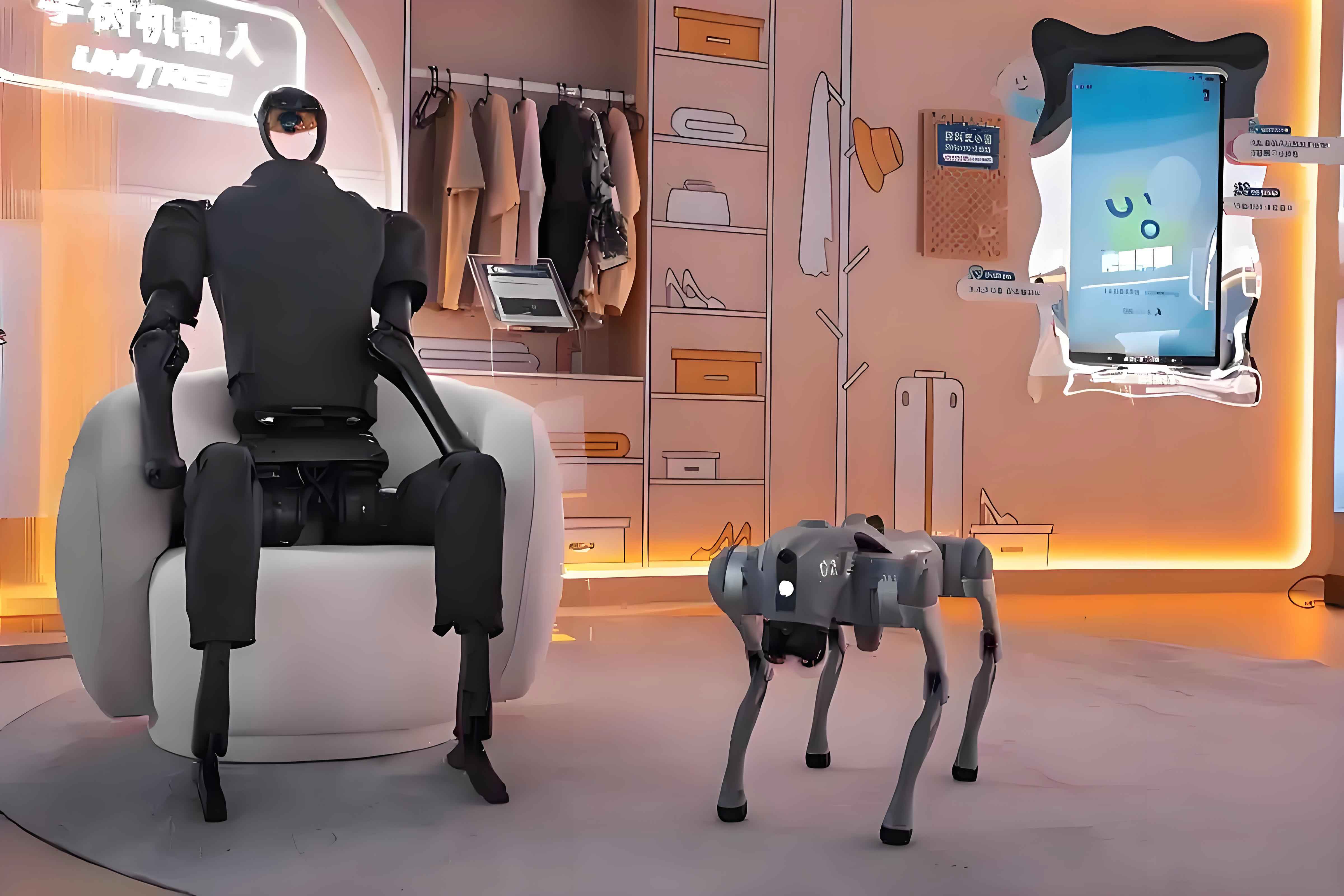
The research arrives at a moment when the humanoid robot is being pushed from controlled laboratory settings into unstructured human environments. Industrial robots have long dominated structured factory floors, but the humanoid robot promises a different kind of versatility. Because its form is modeled after the human body, a humanoid robot can potentially use tools, climb stairs, enter vehicles, and operate in spaces designed for people. This potential explains why governments, universities, and private companies are investing heavily in the field. China’s Ministry of Industry and Information Technology issued guidance calling for the initial establishment of a humanoid robot innovation system by 2025, with batch production and demonstration applications in special operations, manufacturing, and public services. By 2027, the guidance envisions a safer and more reliable industrial chain and supply system, with internationally competitive humanoid robot products.
Despite rapid progress, the humanoid robot remains one of the most difficult machines to control. Unlike a wheeled robot, a humanoid robot is an underactuated system. It cannot directly command its floating base to move. Instead, it must push against the ground through its feet, using contact forces to generate motion. Every step involves a brief loss of balance, a controlled fall, and a rapid recovery. The humanoid robot must coordinate dozens of joints, manage ground reaction forces, and respond to disturbances in real time. The dissertation examined in this report narrows the problem to the lower limbs, treating the upper body as a rigid body to reduce complexity and focus on the core challenges of stability and gait. The humanoid robot studied here has four degrees of freedom per leg, eight active lower-limb joints in total, and a floating base that introduces six virtual degrees of freedom between the world frame and the body frame.
1. From Laboratory Prototypes to Public Demonstrations: The Humanoid Robot Trajectory
The history of the humanoid robot stretches back more than half a century. In 1973, Waseda University introduced WABOT-1, a machine with 26 joints, vision and tactile sensors, and the ability to walk on two legs. It was a foundational moment. WABOT-1 demonstrated that a humanoid robot could, in principle, stand and move like a human. In 1986, Honda began its E-series project, and after more than a decade of iteration, the company introduced ASIMO in 2000. ASIMO could walk dynamically, climb stairs, and interact with people. It became the most recognizable humanoid robot of its era and showed that dynamic balance was not merely a laboratory trick but an achievable engineering target.
Since then, the humanoid robot field has expanded rapidly. Boston Dynamics developed PETMAN and Atlas, using hydraulic actuation to achieve running, jumping, and acrobatic maneuvers. SoftBank’s Pepper, launched in 2014, focused on emotional interaction and became an early commercial service robot. Tesla’s Optimus and Agility Robotics’ Digit represent newer efforts to combine humanoid form with practical tasks in logistics, manufacturing, and service work. Each generation of humanoid robot has pushed control theory, hardware design, and system integration further.
China’s humanoid robot development followed a similar arc. In the 1980s, universities began exploring bipedal locomotion. In 1990, the National University of Defense Technology introduced the country’s first biped walking robot. By 2000, the same institution had produced a more complete humanoid robot with a head, arms, legs, and basic language capability. During the 2000s, universities including Beijing Institute of Technology, Zhejiang University, Northeastern University, and Harbin Institute of Technology tracked and adapted international progress. In the industrial era, UBTech became a prominent Chinese humanoid robot company. Its Alpha 1S robots performed on the Spring Festival Gala stage in 2016, and Walker X later demonstrated complex terrain walking and hand-eye coordination. More recently, Unitree, EngineAI, and AgiBot have introduced humanoid robot platforms capable of running, backflips, and household-oriented interaction. The humanoid robot has moved from a research curiosity to a fast-moving commercial and technological frontier.
Control theory has evolved alongside the hardware. Early humanoid robot control relied on simplified models such as the linear inverted pendulum and quasi-static walking. Researchers used preprogrammed trajectories and joint torque feedback to maintain balance. As computing power increased, dynamic walking became more practical. Whole-body control frameworks optimized joint torques and contact force distribution. Model predictive control allowed the humanoid robot to predict future states and adjust its motion in real time. More recently, reinforcement learning has enabled humanoid robot policies to be trained in simulation and transferred to hardware, though the gap between simulation and reality remains a major challenge. The dissertation places itself within the model-based control tradition, using kinematics, dynamics, stability criteria, and optimization to achieve reliable lower-limb motion.
2. Research Scope: Stable Walking as the First Milestone for a Humanoid Robot
The central premise of the research is straightforward: before a humanoid robot can manipulate objects, climb stairs, or interact socially, it must first walk stably. Stable walking is not a single problem but two tightly coupled problems. The first is stability: the humanoid robot must not fall. The second is gait: the humanoid robot must produce a sequence of foot placements and body motions that allows forward progress. These two problems shape the entire control architecture. The research therefore examines lower-limb kinematics, Jacobian mapping, foot-ground contact forces, static and dynamic stability criteria, gait planning, virtual model control, model predictive control, and robust joint motor control.
The humanoid robot platform used in the study is simplified for analysis. The upper body is treated as a rigid body, reducing the influence of arm swing and torso articulation on lower-limb stability. Each leg has four joints: a hip roll joint, a hip pitch joint, a knee joint, and an ankle pitch joint. The leg links include a side-swing bracket, a thigh link, a shank link, and a foot. The floating base concept is essential. Because the humanoid robot’s body is not fixed to the ground, a virtual six-degree-of-freedom joint is introduced between the world frame and the body frame. This virtual joint includes three translational and three rotational degrees of freedom. The lower-limb motion chain then contains eight active joints. This modeling approach allows the humanoid robot to be treated as a fixed-base system for kinematic analysis while preserving the floating-base dynamics that make walking difficult.
3. Kinematic Modeling of the Humanoid Robot Lower Limbs
3.1 Biological Inspiration and Mechanical Abstraction
The design of the humanoid robot lower limb begins with biological inspiration. The human leg can be abstracted into six major parts: hip joint, thigh, knee joint, shank, ankle joint, and foot. The hip connects the thigh to the pelvis, the knee connects the thigh to the shank, and the ankle connects the shank to the foot. The mechanical version of the humanoid robot follows this anatomical logic. Each leg is built from four joints and three main links. The hip roll joint allows lateral leg movement. The hip pitch joint allows forward and backward swing. The knee joint provides flexion and extension. The ankle pitch joint adjusts foot orientation. This simplified structure retains the essential degrees of freedom needed for walking while remaining tractable for real-time control.
The humanoid robot lower-limb model has eight active joints, four per leg. The body frame is located near the waist. The world frame is fixed to the ground. A transition frame is introduced at the hip height to simplify coordinate transformations. The left and right legs are modeled separately, but their kinematic structures are symmetric. The ankle joint does not affect the foot-end position in the same way as the hip and knee joints, so the position analysis primarily considers the hip roll, hip pitch, and knee angles. The foot orientation is handled separately through the ankle joint.
| Lower-Limb Component | Function in Humanoid Robot Walking | Active Joints per Leg |
|---|---|---|
| Hip roll | Controls lateral leg swing and balance adjustment | 1 |
| Hip pitch | Drives forward and backward leg motion | 1 |
| Knee | Provides flexion and extension for ground clearance and support | 1 |
| Ankle pitch | Adjusts foot orientation and contact force distribution | 1 |
| Total active lower-limb joints | Supports stance and swing phases for both legs | 8 |
3.2 Modified Denavit-Hartenberg Modeling
To describe the relationship between joint angles and foot positions, the research uses a modified Denavit-Hartenberg method. The traditional Denavit-Hartenberg approach can introduce parameter redundancy and singular configurations in dynamic analysis. The modified method adjusts coordinate system definitions and parameter coupling to better handle the closed-chain characteristics of the lower limbs. The body frame is set at the waist, with the x-axis pointing in the direction of motion and the y-axis pointing to the left side of the humanoid robot. The geometry includes waist height, hip spacing, thigh length, shank length, foot link length, and foot sole length.
The left leg is used as the primary example. The coordinate systems are established from the body frame through the hip, thigh, shank, and foot. The transformation matrices are derived for each link. The forward kinematics of the humanoid robot lower limb describes how joint angles produce the foot-end position in the body frame. The inverse kinematics problem is the opposite: given a desired foot position, determine the joint angles. The research derives both analytical and numerical solutions. The analytical solution uses geometric relationships and joint constraints to avoid multiple solutions. The numerical solution uses the forward kinematic model and iterative optimization, with a pseudo-inverse or damped least-squares method. The damping coefficient prevents singularity issues, and joint limits are enforced during iteration. Convergence is typically checked against an error threshold of 1e-6 or a maximum iteration count.
| Transformation | Twist Angle | Link Length | Joint Angle | Link Offset |
|---|---|---|---|---|
| 0 to 1 | 90 degrees | d | -90 + theta1 | 0 |
| 1 to 2 | -90 degrees | 0 | theta2 | l1 |
| 2 to 3 | 0 degrees | l2 | theta3 | 0 |
| 3 to 4 | 0 degrees | l3 | 0 | 0 |
The forward kinematic equations show that the foot-end position depends on the hip roll, hip pitch, and knee angles. The inverse kinematic equations are solved using geometric relationships in the YOZ and XOZ planes. The hip roll angle is determined first, followed by the hip pitch and knee angles. The ankle angle is then calculated from the desired foot orientation. This layered approach reduces the complexity of the inverse kinematic solution and makes it suitable for real-time control of the humanoid robot.
4. Inverse Kinematics and Jacobian Mapping for Humanoid Robot Legs
Inverse kinematics is essential for translating desired foot trajectories into joint commands. The research presents both analytical and numerical methods. The analytical method is intuitive and fast, but it must handle multiple solutions and joint limits. The numerical method is more general and can be used when the kinematic structure becomes more complex. The numerical method iteratively updates joint angles using the Jacobian matrix. The position error and orientation error are computed, and the joint angle update is obtained through a pseudo-inverse or damped least-squares formulation. Joint limits are enforced after each update, and singular configurations are avoided by increasing the damping coefficient when the Jacobian condition number becomes too large.
The Jacobian matrix is a central mathematical tool for the humanoid robot. It maps joint velocities to Cartesian velocities of the foot. For the left leg, the Jacobian relates the hip roll, hip pitch, and knee angular velocities to the linear velocity of the foot in the body frame. The right leg follows the same derivation with sign differences. When the Jacobian is invertible, a desired foot velocity can be converted into joint velocities. This relationship is later used to map desired foot forces into joint torques. The Jacobian also plays a critical role in the control architecture, because both the support-phase force controller and the swing-phase position controller rely on it to translate Cartesian commands into joint-level commands.
The humanoid robot’s floating base introduces an additional layer of complexity. The foot position in the world frame depends on both the body pose and the leg joint angles. The research establishes a transformation between the world frame and the body frame. The body pose includes position and orientation. In simulation, these values are available directly from the virtual sensors. On the real humanoid robot, orientation is obtained from an inertial measurement unit, and position is estimated by integrating velocity estimates from a state estimator such as a Kalman filter. This world-frame kinematic model allows the humanoid robot to plan foot placements and maintain balance relative to the ground.
5. Foot-Ground Contact Force Modeling
Contact is where the humanoid robot meets the world. Without accurate contact force modeling, stable walking is impossible. The research examines several contact models. In the simplest case, each foot is represented by four contact points with three-dimensional forces. However, this model cannot support normal pitch motion for the humanoid robot because it overconstrains the foot. A second model simplifies the contact points but still includes a rolling moment around the x-axis, which prevents proper rolling motion. The third model removes the external moment around the x-axis and is selected because it allows the humanoid robot to execute the required motions without overconstraint.
The foot force distribution is analyzed in both two-dimensional and three-dimensional forms. In the two-dimensional model, vertical and horizontal forces are distributed along the foot sole. These forces are equivalently represented by a resultant force and moment at a single point. In the three-dimensional model, the vertical pressure distribution and horizontal shear stress distribution are considered over the contact surface. The center of pressure, or zero moment point, is derived from the pressure distribution. The research also derives the contact constraint for the stance foot: in the world frame, the stance foot velocity is zero in all three directions. This constraint is essential for keeping the support foot planted while the humanoid robot moves its body forward.
The contact force model also includes friction constraints. The horizontal forces must remain within the friction cone determined by the normal force and the friction coefficient. The normal force must remain positive to ensure contact and below a maximum value to respect actuator and structural limits. These constraints are later embedded into the model predictive controller. For the humanoid robot, contact force modeling is not an abstract exercise. It determines whether the robot can accelerate, decelerate, turn, or recover from a disturbance without slipping or tipping.
6. Stability Criteria for Humanoid Robot Locomotion
Stability is the first requirement for any walking humanoid robot. The research distinguishes between static stability and dynamic stability. Static stability is evaluated by projecting the center of mass onto the support polygon. The support polygon is the smallest convex polygon containing all contact points between the feet and the ground. When the humanoid robot is standing still, the center of mass projection must remain inside this polygon. This criterion is useful for low-speed or quasi-static motion. It is simple and intuitive, but it is not sufficient for dynamic walking, because during walking the center of mass projection may temporarily move outside the support polygon.
Dynamic stability is evaluated using the zero moment point, commonly known as ZMP. The ZMP is the point on the ground where the horizontal moment of the ground reaction force is zero. In a stable humanoid robot, the ZMP must remain inside the support polygon. The ZMP criterion accounts for inertial forces and moments, making it suitable for dynamic walking. The research shows that the center of mass projection and the ZMP coincide only in special cases, such as when the humanoid robot is standing still. During motion, they diverge because of acceleration and angular momentum. The controller must therefore regulate the ZMP rather than simply the center of mass projection.
| Stability Criterion | Core Condition | Typical Application | Limitation |
|---|---|---|---|
| Center of mass projection | Projection remains inside the support polygon | Static standing and very low-speed walking | Ignores inertial effects during dynamic motion |
| Zero moment point | ZMP remains inside the support polygon | Dynamic walking and balance recovery | Requires accurate contact force and state estimation |
The zero moment point is defined through the ground reaction force and moment. In two dimensions, the ZMP is the point where the moment of the distributed vertical force is zero. In three dimensions, the ZMP is the point where the horizontal moment of the ground reaction force is zero. The research derives the ZMP equations from the foot force distribution and relates them to the center of mass motion. For a linear inverted pendulum model, the ZMP position is expressed as a function of the center of mass position and acceleration. This relationship is used extensively in gait planning and model predictive control. The humanoid robot can therefore plan a desired ZMP trajectory and generate a corresponding center of mass trajectory, or it can optimize contact forces to track a desired body motion while keeping the ZMP within the support polygon.
7. Gait Planning for Humanoid Robot Walking
7.1 Gait Cycle and Phase Decomposition
Gait planning determines how the humanoid robot moves its legs over time. The walking cycle is divided into stance and swing phases. During the stance phase, the foot is in contact with the ground and supports the body. During the swing phase, the foot leaves the ground and moves to the next foothold. The gait cycle also includes single-support and double-support phases. In single support, only one foot is on the ground. In double support, both feet are in contact. The research analyzes the human walking cycle and abstracts it into a form suitable for the humanoid robot. The cycle begins with a start phase, transitions into periodic walking, and ends with a stop phase. The periodic walking phase is the main focus.
Key gait parameters include step length, step width, step frequency, and duty factor. Step length is the horizontal distance between the two feet during double support. Step width is the lateral distance between the feet. Step frequency is the number of steps per unit time. Duty factor is the fraction of the gait cycle spent in stance. The research focuses on forward walking, although backward walking, turning, and marching are also mentioned as basic gaits. The humanoid robot starts from a crouched double-support posture to lower its center of mass and increase stability. It then shifts its weight to one leg, swings the other leg forward, lands, and repeats the process. The upper body is treated as a rigid body, so the gait is generated primarily by the lower limbs.
Two foot-ground contact strategies are considered. The first is full-sole parallel contact, in which the foot remains parallel to the ground throughout the gait cycle. The second is rolling contact, in which the heel touches first, followed by the sole, and the support foot rolls from heel to toe. The rolling contact strategy is more biologically realistic and can produce smoother force transitions, but it requires precise coordination of multiple joints and high-bandwidth torque control. Given the actuator bandwidth and state estimation accuracy of the available humanoid robot platform, the research selects the full-sole parallel strategy. This choice reduces kinematic complexity and simplifies the control problem while still allowing stable walking.
7.2 Bézier Curve Trajectory Planning
Bézier curves are used to generate smooth foot trajectories. A Bézier curve is defined by control points, and its shape can be adjusted without complex optimization. The research uses a sixth-degree Bézier curve with seven control points. This choice allows control over position, velocity, and acceleration at the start and end of the swing phase. The trajectory is planned in the x and z directions. The control points are selected to satisfy initial and final position, velocity, and acceleration constraints. Because the curve is symmetric, the middle control point is placed at half the step length and at a specified height. The step length, step height, and middle coefficient determine the final trajectory.
In a simulation example, the step length is set to 85 mm, the step height is 35 mm, and the swing time is 1 s. The position, velocity, and acceleration curves show smooth transitions. The velocity starts and ends near zero, and the acceleration remains continuous. This smoothness is important because abrupt changes in foot velocity or acceleration can cause impact forces, slip, or instability. The Bézier curve method is computationally efficient and suitable for real-time implementation on the humanoid robot. It also allows the swing leg to clear the ground and land softly, reducing the disturbance to the support leg.
7.3 Linear Inverted Pendulum Model
The linear inverted pendulum model is another core tool for gait planning. In this model, the humanoid robot is simplified as a point mass at the center of mass, connected to the ground by a massless telescopic leg. The center of mass height is assumed constant. The ground reaction force passes through the center of mass, and the moment is assumed to be zero. Under these assumptions, the horizontal motion of the center of mass follows a linear differential equation. The model predicts that the center of mass will diverge exponentially unless the foot placement and timing are properly controlled.
The research uses orbital energy to describe the state of the linear inverted pendulum. Orbital energy is a virtual potential that reflects the motion state of the center of mass. For a given support foot position and center of mass height, the orbital energy determines whether the center of mass will cross the apex, reverse direction, or diverge. By choosing the orbital energy at each step, the humanoid robot can achieve a continuous walking pattern. The support foot switching condition is derived by equating the orbital energy before and after the switch. This leads to a simple relationship between step length, center of mass position, and orbital energy. The linear inverted pendulum model is extended to three dimensions, where the center of mass is constrained to a plane. The resulting equations relate the center of mass acceleration to the ZMP position. This model is used to estimate body velocity and predict future foot placement. It provides a fast, low-dimensional representation of the humanoid robot’s dynamics and is particularly useful for planning and control at the gait level.
8. Dynamic Control Architecture: VMC, MPC, and Robust Joint Control
8.1 Virtual Model Control for Support Phases
The first control approach examined in the research is virtual model control, or VMC. The idea is to define virtual forces and torques at the body center of mass and then map them to joint torques through the Jacobian. In single support, the stance leg is modeled as a chain from the foot to the body. The virtual vertical force and body pitch moment are selected as control inputs, and the horizontal virtual force is computed from the dynamic constraint. In double support, both legs contribute to the virtual force and moment. The force distribution between the legs is resolved through a matrix equation. A state machine coordinates the transitions between single support and double support.
Virtual model control is intuitive and computationally light. It can produce stable standing and simple walking motions. However, the research finds that VMC has significant limitations. It does not explicitly optimize ground reaction forces, and it struggles to adjust body posture when the humanoid robot encounters disturbances. The humanoid robot may walk, but the body attitude may not be well regulated. This limitation motivates the introduction of model predictive control.
8.2 Model Predictive Control for Support-Phase Force Optimization
Model predictive control, or MPC, is a model-based optimal control method. At each control step, it predicts the future evolution of the system over a finite horizon, solves an optimization problem, and applies only the first control input. The process repeats at the next step, creating a receding-horizon feedback law. The research examines two MPC strategies for the humanoid robot. The first is a ZMP-preview control approach that optimizes the center of mass trajectory to track a desired ZMP. The second is a force-based MPC approach that optimizes support-phase ground reaction forces while using PD control for the swing leg.
The ZMP-preview approach discretizes the linear inverted pendulum dynamics and defines a cost function that penalizes ZMP tracking error, state changes, and control effort. A preview controller uses future ZMP references to generate the center of mass trajectory. Simulations show that a standard preview algorithm can track the ZMP, but an improved algorithm that accounts for accumulated ZMP error performs better when the preview time is short. When the preview time is large, the difference between the two algorithms becomes small. The research notes that increasing the preview time beyond about 2 s does not provide significant additional benefit. Although ZMP-preview control can produce stable walking, it is relatively stiff and performs poorly on uneven terrain or in the presence of strong disturbances.
The second approach, force-based MPC, is selected as the main dynamic walking controller. The humanoid robot is modeled as a single rigid body with mass and inertia. The control inputs are the contact forces and moments at the feet. The dynamics relate the center of mass acceleration and angular momentum rate to the external forces and moments. The model is linearized around a reference trajectory. The MPC problem minimizes tracking error and control effort subject to dynamic constraints, friction cone constraints, normal force limits, and torque limits. The resulting quadratic program is solved at each control step. The support leg receives force and moment commands, which are mapped to joint torques through the Jacobian. The swing leg is controlled by a Cartesian PD controller that tracks the desired foot trajectory. The PD controller acts like a virtual spring-damper attached to the foot. Because the foot mass is much smaller than the body mass, it can be neglected in the force calculation. The resulting control architecture coordinates support-phase force optimization with swing-phase position tracking.
The MPC controller uses a simplified single-rigid-body model, but it captures the essential dynamics of the humanoid robot. It can adjust ground reaction forces to maintain balance, reject disturbances, and follow a desired body trajectory. The friction cone constraint prevents slipping. The normal force constraint ensures positive contact and respects structural limits. The torque limit ensures that the joint motors are not overloaded. The quadratic programming formulation is computationally efficient and suitable for real-time control. In simulation and experiments, the force-based MPC produces stable dynamic walking on flat ground.
8.3 Robust Control for High-Precision Joint Motor Tracking
At the joint level, the research introduces a model-based robust controller to replace conventional PD control. The motivation is that joint friction, parameter uncertainty, and external disturbances can degrade trajectory tracking. The robust controller is designed for a general uncertain mechanical system. The dynamics include inertia, Coriolis and centrifugal terms, gravity, and friction. Friction is modeled with viscous and Coulomb components. The sign function in the Coulomb friction model is approximated by a hyperbolic tangent function to avoid discontinuity. The controller consists of three terms: a nominal control term based on the Udwadia-Kalaba equation, an initial condition compensation term, and an uncertainty compensation term. The stability analysis uses a Lyapunov function to prove uniform boundedness and uniform ultimate boundedness. The error bound can be adjusted through design parameters.
The robust controller is first tested on a permanent magnet synchronous motor model. The motor dynamics include stator resistance, permanent magnet flux linkage, d-axis and q-axis inductances, electromagnetic torque, damping coefficient, inertia, and load torque. The controller is simulated with step and sinusoidal reference signals. The results show fast response, small overshoot, and accurate tracking. The robust controller is then implemented on a single-joint motor platform. Compared with PID control, the robust controller achieves faster response and smaller tracking error. The research notes that the robust controller has not yet been validated in full dynamic walking because of hardware platform limitations, but the single-joint results suggest that it could improve joint-level tracking in future humanoid robot systems.
| Control Method | Main Role in Humanoid Robot Walking | Strengths | Limitations Identified in the Research |
|---|---|---|---|
| Virtual model control | Maps virtual forces and moments to joint torques for support phases | Intuitive, computationally light, useful for standing and simple walking | Weak body posture regulation and limited disturbance rejection |
| Model predictive control | Optimizes support-phase ground reaction forces and coordinates swing-leg PD control | Handles constraints, rejects disturbances, supports dynamic walking | Requires accurate state estimation and real-time quadratic programming |
| Robust joint motor control | Replaces PD control for high-precision joint trajectory tracking | Fast response, low overshoot, smaller tracking error under uncertainty | Not yet validated in full dynamic walking on the humanoid robot |
9. Simulation and Experimental Validation on a Humanoid Robot Prototype
9.1 Prototype and Control System Composition
The control methods are validated on a physical humanoid robot prototype and in simulation. The prototype has 17 degrees of freedom. Each arm has four degrees of freedom, each leg has four degrees of freedom, and the waist has one degree of freedom. The humanoid robot integrates a MID-360 LiDAR and a D435 depth camera in the head for environmental and visual perception. The leg joints use the M107 motor. This motor has a maximum torque of 360 N·m and a maximum pull force of 10000 N under a 3.5 cm equivalent moment arm. It uses a hollow-shaft design, which reduces weight and improves compactness. Dual encoders provide accurate position and speed feedback.
The control system uses a distributed architecture. An upper monitoring system communicates with the main control unit over Ethernet. It collects robot state data, encodes motion commands, preprocesses sensor signals, and provides real-time visualization. The main computing unit uses an AMD R9-7940HS processor. It handles swing-leg trajectory control and support-phase balance adjustment. The swing-leg module uses gait parameters and joint encoder feedback to generate foot-end position commands. The support-phase module uses inertial measurement unit data, body attitude angles, angular velocity, and center of mass state estimates to generate posture compensation commands. The two modules run in parallel with a 1 ms control cycle. A motion control solver using an i5-1235U processor receives data from the upper algorithm processor over Ethernet and communicates with the joint motors over RS485. Each joint motor includes a driver board, stator, rotor, and planetary reducer. The dual encoders measure position and speed for closed-loop control and state estimation.
| System Element | Specification or Function |
|---|---|
| Total degrees of freedom | 17 |
| Arm degrees of freedom | 4 per arm |
| Leg degrees of freedom | 4 per leg |
| Waist degrees of freedom | 1 |
| Head sensors | MID-360 LiDAR and D435 depth camera |
| Leg joint motor | M107 with maximum torque of 360 N·m and maximum pull of 10000 N at 3.5 cm equivalent arm |
| Motor feedback | Dual encoders for position and speed |
| Main computing unit | AMD R9-7940HS processor |
| Motion control solver | i5-1235U processor |
| Communication | Ethernet and RS485 |
| Control cycle | 1 ms |
9.2 Static Standing and PVT Stability
The first experimental milestone is static standing. The humanoid robot must hold a stable crouched posture before dynamic walking can be attempted. The research uses position, velocity, and torque control, often referred to as PVT control, to achieve static stability. In the MuJoCo simulation, the body center of mass height is set to 0.9 m, the hip width is 0.15 m, and the initial knee angle is 0.1. The desired foot positions in the body frame and the joint motor PVT parameters are specified. The inverse kinematic solver adjusts the joint angles and foot positions to achieve the desired posture. The upper body is given an initial attitude and held fixed.
In simulation, the humanoid robot shows small oscillations at the beginning, but it stabilizes within about 2 s. The body attitude angles settle near zero. The joint angles follow their references, and the angular velocities return to near zero. The joint torques become symmetric and stable. These results confirm that the PVT controller can maintain the initial posture. The same controller is then deployed on the physical humanoid robot. In the experiment, the body attitude changes only slightly over 6 s. The joint angle errors remain within 0.5 degrees, and most are within 0.1 degrees. The angular velocities remain near 0 deg/s with some noise and fluctuation, which is considered acceptable. The joint torques are roughly symmetric between the left and right legs. The static standing experiment demonstrates that the humanoid robot can maintain a stable initial posture, which is essential for the subsequent dynamic walking experiments.
9.3 Dynamic Walking Experiments
After static stability is achieved, the research moves to dynamic walking. The force-based MPC controller is implemented in MuJoCo first. The controller parameters are tuned to achieve stable walking. Once the simulation results are satisfactory, the controller is deployed on the physical humanoid robot. The walking experiments are conducted on flat ground. Joint encoders and torque sensors measure the position, speed, and torque of the leg motors. An inertial measurement unit measures the body attitude angles, including roll, pitch, and yaw. The data show that the joint torques remain within reasonable limits. The body attitude angles are generally stable, although the yaw angle shows somewhat larger fluctuations. The research attributes this to sensor sensitivity. Roll and pitch remain within normal ranges. The humanoid robot walks stably, and the experimental data support the feasibility of the MPC-based dynamic walking controller.
The dynamic walking experiments also show the importance of the swing-leg PD controller. The MPC controller optimizes the support-phase ground reaction forces, but it does not directly control the swing foot. The swing leg must follow a planned trajectory to ensure proper foot placement and ground clearance. The Cartesian PD controller provides this tracking. The combination of support-phase force optimization and swing-phase position control allows the humanoid robot to maintain balance while advancing. The gait cycle is generated by a timing-based planner, and the state machine switches between support phases. The humanoid robot can walk forward on flat ground without falling, demonstrating the effectiveness of the overall control architecture.
9.4 Single-Joint Motor Robust Control Experiments
The robust joint controller is tested on a single-joint motor platform. Step response and sinusoidal tracking experiments are performed. The robust controller is compared with a PID controller. In the step response, the robust controller reaches the reference faster and with smaller overshoot. In the sinusoidal tracking experiment, the robust controller follows the reference trajectory more closely. The tracking error is smaller than that of the PID controller. These results indicate that the robust controller can improve joint-level tracking performance. Because the full humanoid robot walking controller still uses PD control at the joint level in the experiments, the robust controller has not yet been integrated into dynamic walking. However, the single-joint results provide a strong basis for future integration. If the robust controller is applied to all leg joints, it may improve trajectory tracking accuracy and disturbance rejection during walking.
| Experiment | Controller Used | Observed Outcome |
|---|---|---|
| Static standing in MuJoCo | PVT control | Small initial oscillation, stabilization within about 2 s, joint angles and torques settle |
| Static standing on physical humanoid robot | PVT control | Body attitude changes slightly over 6 s, joint angle errors mostly within 0.1 degrees to 0.5 degrees, torques symmetric |
| Dynamic walking on flat ground | Force-based MPC plus swing-leg PD control | Stable walking, joint torques within reasonable limits, yaw fluctuations attributed to sensor sensitivity |
| Single-joint motor step response | Robust control compared with PID | Faster response, smaller overshoot |
| Single-joint motor sinusoidal tracking | Robust control compared with PID | Smaller tracking error and better trajectory following |
10. Conclusions and Future Research Directions for Humanoid Robot Locomotion
The research delivers a complete model-based control pipeline for a humanoid robot lower limb. It begins with kinematic modeling, derives forward and inverse kinematics, and establishes the Jacobian relationship between joint space and Cartesian space. It then models foot-ground contact forces and introduces static and dynamic stability criteria. Gait planning is addressed with Bézier curves and the linear inverted pendulum model. At the control level, the work progresses from virtual model control to model predictive control and finally to robust joint motor control. Simulations and experiments validate the main components. Static standing is achieved through PVT control. Dynamic walking is achieved through force-based MPC and swing-leg PD control. Joint-level tracking is improved through a robust controller that outperforms PID in single-joint experiments.
The research also identifies several limitations and future directions. The robust controller was not validated in full dynamic walking because of hardware platform limitations. Future work could integrate the robust controller into all leg joints of the humanoid robot and test it during walking. The upper body was treated as a rigid body, so the influence of arm swing and torso motion was not considered. Future studies could include upper-body dynamics and investigate how a humanoid robot maintains stability when the upper body moves. The control methods used in the research are model-based, which means they require accurate models and careful parameter tuning. This can be time-consuming and difficult to deploy. Future work could explore reinforcement learning or hybrid model-based and learning-based approaches to reduce tuning effort and improve adaptability. The humanoid robot field is moving quickly, and the next generation of machines will need to combine robust low-level control with intelligent high-level decision-making.
11. Key Takeaways for the Humanoid Robot Community
- The humanoid robot must solve stability and gait together; neither can be treated in isolation.
- Kinematic modeling, Jacobian mapping, and contact force modeling form the foundation for lower-limb control.
- Static stability based on the center of mass projection is useful for standing but insufficient for dynamic walking.
- The zero moment point remains a practical and widely used dynamic stability criterion for the humanoid robot.
- Bézier curves provide smooth foot trajectories, while the linear inverted pendulum model provides efficient gait planning and body velocity prediction.
- Virtual model control is intuitive but limited in posture regulation and disturbance rejection.
- Force-based model predictive control offers a stronger framework for dynamic walking because it optimizes support-phase ground reaction forces under friction, force, and torque constraints.
- Swing-leg PD control complements support-phase force optimization by tracking the desired foot trajectory.
- Robust joint motor control can improve tracking accuracy and response speed, though full integration into walking remains future work.
- The humanoid robot prototype with 17 degrees of freedom, distributed control, LiDAR, depth camera, and high-torque M107 motors provides a realistic platform for validating these methods.
The broader significance of this research is that it turns abstract control theory into a working walking humanoid robot. It does not claim that the humanoid robot is ready for every real-world task. Instead, it establishes a rigorous foundation for stable lower-limb motion. The humanoid robot community can build on this foundation by expanding the controller to the full body, improving state estimation, integrating learning-based adaptation, and testing on more complex terrain. As the humanoid robot continues its transition from demonstration to deployment, studies like this one will help ensure that the next generation of machines can walk with the stability, efficiency, and confidence needed for everyday human environments.