
The precise transmission of motion in industrial robots, automated machinery, and other high-precision applications relies heavily on the performance of its core drive components. Among these, the Rotary Vector (RV) reducer has emerged as a preeminent solution, distinguished by its compact size, high torque density, exceptional torsional rigidity, and remarkable positioning accuracy with minimal backlash. The heart of this two-stage reduction mechanism lies in its unique cycloidal-pin gear planetary transmission. The geometric perfection and precise modification of the cycloidal gear’s tooth profile are paramount, directly dictating the RV reducer’s load distribution, transmission efficiency, operational smoothness, and ultimately, its service life and precision retention. This investigation delves into the intricate world of the cycloidal gear tooth profile, employing empirical measurement, mathematical modeling, and comparative analysis to unravel its characteristics and establish a robust methodology for its definition.
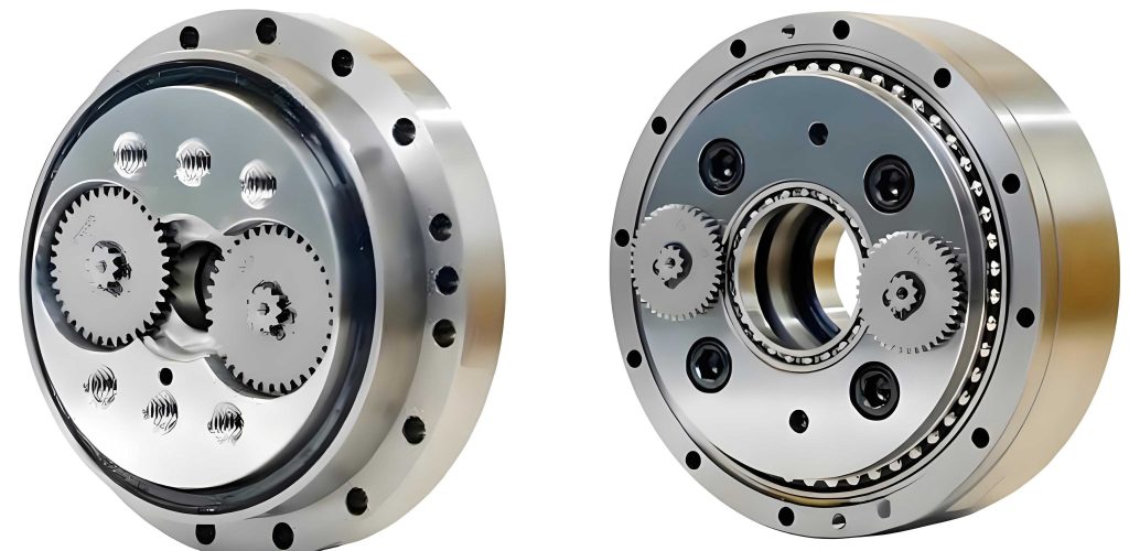
The fundamental working principle of the RV reducer is a harmonious combination of a primary planetary stage and a secondary cycloidal stage. The input rotation from a servo motor is first transmitted to a sun gear, which meshes with multiple planetary gears to achieve the first stage of speed reduction. Crucially, these planetary gears are rigidly connected to eccentric crankshafts. As the planetary gears rotate, they drive these crankshafts, which in turn cause the cycloidal gears to undergo an eccentric, planetary motion. The cycloidal gears mesh with a stationary ring of pin gears (the pinwheel) housed within the rigid casing. Due to the specific epitrochoidal shape of the cycloidal gear teeth and the constraint provided by the fixed pins, this eccentric motion is transformed. The cycloidal gear experiences both a revolution around the central axis of the RV reducer (carried by the crankshaft) and a reverse rotation about its own axis. This reverse rotation, which constitutes the second and most significant stage of reduction, is output through a compact and robust force-transmitting mechanism (often a set of needle rollers or a flange) connected to the output shaft. The overall reduction ratio $i_{RV}$ of this sophisticated system can be expressed as:
$$ i_{RV} = 1 + \frac{Z_p}{Z_c} $$
where $Z_p$ is the number of pin gears on the stationary ring and $Z_c$ is the number of teeth on the cycloidal gear. This equation highlights the direct relationship between the gear teeth counts and the high reduction ratios achievable by the RV reducer.
Theoretical Foundation of the Cycloidal Tooth Profile
The ideal, mathematically pure tooth form of a cycloidal gear that meshes perfectly with a theoretical pinwheel (with zero clearance) is known as the standard or conjugate profile. To derive this profile, we establish a coordinate system fixed to the cycloidal gear. The trajectory of the center of a pin gear, as observed from the rotating cycloidal gear, forms an epitrochoid. The standard tooth profile is then generated as the inner envelope curve of all possible positions of the pin circle (representing the pin gear and its bushing) as it rolls along this epitrochoidal path. The parametric equations for this standard cycloidal gear tooth profile are given by:
$$ x_s = R_p \sin\phi – \frac{K_1}{Z_p} \sin(Z_p \phi) – r_p \cos\beta $$
$$ y_s = R_p \cos\phi – \frac{K_1}{Z_p} \cos(Z_p \phi) + r_p \sin\beta $$
where:
$R_p$ is the radius of the pin gear center circle (Pitch Circle Radius),
$r_p$ is the radius of the pin gear (including its bushing),
$Z_p$ is the number of pin gears,
$\phi$ is the generating angle (the rotational parameter),
$K_1 = \frac{R_p \cdot e}{a}$ is the curtate ratio or shortening coefficient, with $e$ being the eccentricity of the crankshaft,
and $\beta$ is the pressure angle variable, defined as:
$$ \cos\beta = \frac{K_1 \sin(Z_p \phi) – \sin\phi}{\sqrt{1 + K_1^2 – 2K_1 \cos(Z_p \phi)}}, \quad \sin\beta = \frac{-K_1 \cos(Z_p \phi) + \cos\phi}{\sqrt{1 + K_1^2 – 2K_1 \cos(Z_p \phi)}} $$
However, a perfectly conjugate profile is impractical for a real-world RV reducer. Essential operational requirements such as lubrication, compensation for thermal expansion, accommodation of manufacturing tolerances, and control of backlash necessitate intentional modifications to this standard profile. This process is known as “tooth profile modification” or “correction.” The primary methodologies employed are:
- Offset Modification (Profile Shift): Altering the pin gear center circle radius $R_p$ by a small amount $\Delta R_p$.
- Equidistant Modification: Altering the effective pin gear radius $r_p$ by a small amount $\Delta r_p$.
- Rotational Angle Modification: Introducing a slight phase shift $\Delta \phi$ in the generating angle.
In practice, a combination of these methods is typically used to optimize contact stress distribution and backlash. The general modified tooth profile equations become:
$$ x_m = (R_p \pm \Delta R_p) \sin(\phi \pm \Delta\phi) – \frac{K_1′}{Z_p} \sin[Z_p (\phi \pm \Delta\phi)] – (r_p \pm \Delta r_p) \cos\beta’ $$
$$ y_m = (R_p \pm \Delta R_p) \cos(\phi \pm \Delta\phi) – \frac{K_1′}{Z_p} \cos[Z_p (\phi \pm \Delta\phi)] + (r_p \pm \Delta r_p) \sin\beta’ $$
where $K_1’$ is the modified curtate ratio, and $\beta’$ is calculated using the modified parameters. The precise combination and magnitude of $\Delta R_p$, $\Delta r_p$, and $\Delta \phi$ are the core intellectual property and optimization challenge for manufacturers of high-performance RV reducers.
Empirical Measurement and Data Acquisition
To bridge theory and practice, a physical inspection of a critical component was conducted. The subject was a cycloidal gear from a commercially produced RV-40E type reducer. The goal was to capture its true, as-manufactured tooth form with high fidelity. For this task, a precision coordinate measuring machine (CMM), specifically a Leitz PMM544 model, was employed. This instrument offers micron-level accuracy, making it ideal for reverse-engineering and quality verification of精密 parts like those found in an RV reducer.
The measurement strategy was meticulous. A coordinate system was established with its origin at the theoretical geometric center of the cycloidal gear. Data points were sampled densely along the entire tooth profile contour, with a target density of approximately 20 points per millimeter. This high-resolution scanning was essential to capture the subtle nuances of the profile, especially in the critical transition zones between the convex and concave sections of the tooth flank. In total, over 9,300 discrete $(x, y)$ coordinate pairs were collected from a single cycloidal gear. The key dimensional parameters identified for the RV-40E were:
| Parameter | Symbol | Value (mm) | Description |
|---|---|---|---|
| Pin Circle Radius | $R_p$ | 67.5 | Radius to the centers of the pin gears. |
| Pin Gear Radius | $r_p$ | 3.0 | Radius of the pin gear bushing. |
| Crank Eccentricity | $e$ | 1.5 | Eccentricity of the crankshaft. |
| Number of Pin Gears | $Z_p$ | 40 | Teeth on the fixed ring. |
| Number of Cycloid Teeth | $Z_c$ | 39 | Teeth on the moving cycloidal gear. |
Data Processing and Profile Segmentation Analysis
The raw point cloud data was not uniformly distributed. The profile of a cycloidal gear tooth is not a single continuous curve but comprises distinct regions: convex segments (tooth crests), concave segments (tooth roots), and the critical transition zones connecting them. These transition zones are particularly important for the lubrication and smooth engagement/disengagement of the pin in the RV reducer. The dataset was therefore segmented into these three categories for specialized analysis.
A key hypothesis was that the convex and concave regions might be closely approximated by circular arcs—a common simplification in gear analysis. To test this and extract parameters, the method of least squares fitting was applied separately to the points belonging to each convex and concave region. This method finds the circle that minimizes the sum of the squared distances from all data points in the set to the circle’s circumference, providing an optimal “best-fit” radius and center location.
The results of this arc-fitting analysis for the concave and convex regions are summarized below:
| Profile Region | Number of Fitted Arcs | Average Fitted Radius (mm) | Mean Fitting Error (mm) | Radius of Arc Centers (mm) |
|---|---|---|---|---|
| Concave (Root) | 10 | 3.0736 | ±0.0019 | ~62.7710 |
| Convex (Crest) | 10 | 3.1229 | ±0.0041 | ~59.1792 |
The analysis yielded profound insights. First, the average concave radius (3.0736 mm) is slightly larger than the measured pin gear radius (3.0 mm). This intentional clearance is a hallmark of modification, facilitating the formation of an oil film. Second, the convex radius is larger than the concave radius, indicating a non-conjugate, modified profile. Third, and most telling, the locus of centers for the concave arcs lies at a larger radius (~62.77 mm) than the locus for the convex arcs (~59.18 mm). This offset means that during meshing in the RV reducer, the pin does not roll purely but has a small sliding component, which must be properly managed with lubrication.
The transition zones, however, revealed the limitation of the simple arc-fitting model. When the best-fit convex and concave arcs were extended, they did not intersect smoothly. A significant gap on the order of 0.05–0.06 mm was observed in the normal direction between the extrapolated arcs. This gap was an order of magnitude larger than the fitting errors within the pure convex/concave regions. This unambiguously proved that the transition in an actual RV reducer cycloidal gear is not a simple circular arc blend. It is a sophisticated, purposefully designed curve that ensures continuous contact and proper force transmission as the pin moves from the convex to the concave flank.
Derivation of a Comprehensive Tooth Profile Equation
Given the inadequacy of piecewise circular arcs, especially in the transition zone, the focus shifted to synthesizing a single, continuous mathematical model that could describe the entire measured profile. By working backwards from the measured data and the known design parameters of the RV-40E reducer, a modified tooth profile equation was reverse-engineered. This process involved inferring the specific combination and values of the modification parameters ($\Delta R_p$, $\Delta r_p$, $\Delta \phi$) that would yield a theoretical curve best matching the empirical data.
The derived parametric equations for the modified cycloidal gear in the RV reducer are presented below. Note the introduction of a modification function $S(t)$ which blends the different correction methods:
$$ X(t) = \left(R_p – \Delta R(t)\right) \cos\left(\frac{Z_c}{Z_p}t\right) – \left( \frac{K_1′}{Z_p} – \delta(t) \right) \cos\left( \left(1 + \frac{Z_c}{Z_p}\right) t \right) $$
$$ Y(t) = -\left(R_p – \Delta R(t)\right) \sin\left(\frac{Z_c}{Z_p}t\right) + \left( \frac{K_1′}{Z_p} – \delta(t) \right) \sin\left( \left(1 + \frac{Z_c}{Z_p}\right) t \right) $$
For the specific RV-40E case, with inferred modification, this simplifies to a working model:
$$ X(t) = (67.5 – 3S(t)) \cos(0.02564t) – (1.29466 – 2.42779S(t)) \cos(1.02564t) $$
$$ Y(t) = (67.5 – 3S(t)) \sin(-0.02564t) + (1.29466 – 2.42779S(t)) \sin(1.02564t) $$
where the modification blend function $S(t)$ is:
$$ S(t) = \left(1.65491 – 1.61852 \cos t\right)^{-1/2} $$
and the parameter $t$ (related to the generating angle $\phi$) spans a specific interval, e.g., $t \in [0, 6.12611]$, to define one complete tooth flank of the RV reducer’s cycloidal gear.
A final coordinate rotation (by ~0.24171 radians) aligns this derived profile with the measurement coordinate frame:
$$ x = X \cos(0.24171) – Y \sin(0.24171) $$
$$ y = X \sin(0.24171) + Y \cos(0.24171) $$
Comparative Analysis and Practical Validation
The performance of the arc-fitting method and the derived equation method was rigorously compared against the actual measured data. The following table summarizes the key findings regarding profile error:
| Modeling Approach | Error in Convex/Concave Regions | Error in Transition Zone | Continuity | Practical Utility |
|---|---|---|---|---|
| Piecewise Arc Fitting | Excellent (< 0.004 mm) | Poor (~0.055 mm gap) | Discontinuous | Low – Useful only for approximate analysis of specific regions. |
| Derived Equation Model | Excellent (< 0.002 mm) | Excellent (< 0.002 mm) | Fully Continuous | High – Accurately represents the entire functional tooth form. |
Visually, when overlaid with the measured data and magnified, the derived equation profile was virtually indistinguishable from the actual scanned profile across the entire tooth, including the problematic transition. In contrast, the arc-fit model showed a clear and functionally significant divergence in the transition area.
To move from theory to tangible proof, a new cycloidal gear was manufactured based solely on the parameters and modification logic embedded within the derived equations. This prototype gear was then assembled into an RV reducer and subjected to rigorous testing on a dedicated fatigue life and precision evaluation bench. The performance results were critical: the reducer incorporating the equation-derived gear exhibited equivalent or superior performance in terms of transmission accuracy, torsional stiffness, backlash, and rated lifespan compared to units with the original gear. This practical validation confirmed that the mathematical model accurately captures the essential functional geometry of the RV reducer’s cycloidal gear.
Conclusions and Implications for RV Reducer Design
This comprehensive study, encompassing精密 measurement, advanced data analysis, mathematical modeling, and physical validation, yields several pivotal conclusions regarding the cycloidal gear within an RV reducer:
- The tooth profile is a sophisticated, continuously modified curve. The empirical data definitively shows that the operational profile is not standard, nor is it composed of simple circular arcs. It is the result of precise compound modifications (likely a combination of offset, equidistant, and angle corrections) tailored to optimize the RV reducer’s performance.
- The transition zone is critically important. The region connecting the convex and concave flanks is a uniquely designed curve, not a simple circular fillet. Its geometry is essential for ensuring smooth meshing, proper lubrication entry, and controlled stress distribution as pins engage and disengage in the RV reducer mechanism.
- A continuous mathematical model is superior to piecewise approximation. For design, analysis, and manufacturing, a single set of parametric equations that accurately describes the entire active profile—like the one derived—is far more practical and reliable than attempting to stitch together multiple circular arcs. This model faithfully replicates the gear’s functional form with micron-level accuracy.
- Modification strategy is the core technology. The ultimate performance of an RV reducer—its precision, backlash, efficiency, load capacity, and noise characteristics—is predominantly governed by the specific type, magnitude, and combination of tooth profile modifications applied to the cycloidal gear. Mastering the relationship between modification parameters and system-level performance is the key differentiator in advanced RV reducer design and manufacturing.
The pursuit of perfection in the RV reducer is, in large part, the pursuit of the optimal cycloidal tooth profile. As demands for higher precision, greater reliability, and more compact designs increase, the insights gained from such detailed geometrical studies will continue to drive innovation in this fundamental component of modern precision motion control.