
The development and integration of robotic systems across various industries represents a significant technological advancement. Within the textile and apparel manufacturing sector, the concept of “robots replacing human labor” has emerged as a practical strategy for achieving sustainable development. While numerous robotic solutions have been introduced for specific textile applications, a critical gap persists in fully automated garment production lines: the autonomous grasping and manipulation of flexible fabrics. This operation, which remains largely manual, breaks the continuity of intelligent manufacturing systems. The dexterous robotic hand, serving as the end-effector that directly interacts with the environment, offers a promising solution to bridge this gap and complete the automated workflow.
A dexterous robotic hand is essentially a complex system of coordinated robotic manipulators. Research into its capabilities encompasses multiple challenging domains, including kinematics, dynamics, and geometrical analysis. Due to the high cost and physical constraints of prototyping advanced manipulators, simulation-based analysis has become an indispensable tool. Utilizing software like Matlab to model the three-dimensional structure and simulate the dynamic behavior of a dexterous robotic hand provides invaluable insights prior to physical implementation. This work focuses on the comprehensive modeling, trajectory planning, and simulation of a three-fingered dexterous robotic hand specifically designed for the stable grasping of soft, pliable fabrics.
Structural Design of the Three-Fingered Dexterous Robotic Hand
The human hand’s unparalleled dexterity stems from its ability to reconfigure its posture to accommodate objects of varying shapes, sizes, and material properties. For a dexterous robotic hand, the number of fingers critically influences the number of potential contact points with an object, thereby affecting grasp stability, manipulability, and the range of feasible tasks. Grasping a pile of flexible fabric, whose shape is inherently uncertain and non-rigid, presents a significant challenge, placing high demands on the hand’s design.
From a principles of mechanics perspective, a two-finger gripper can provide force closure in one direction. However, a two-point contact grasp on a fabric sheet lacks constraints against rotation about the axis connecting the two contact points, leading to potential slippage and instability. In contrast, three points not colinear define a plane and can stably constrain an object in space. Therefore, a three-fingered configuration is the minimum necessary for achieving a stable and reliable grasp on flexible fabrics. While increasing the number of fingers enhances potential dexterity, it also introduces kinematic redundancy, significantly complicating the mechanical design, control algorithms, and actuation systems. For an optimal balance between functionality, complexity, and cost-effectiveness, a three-fingered architecture is selected for this dexterous robotic hand.
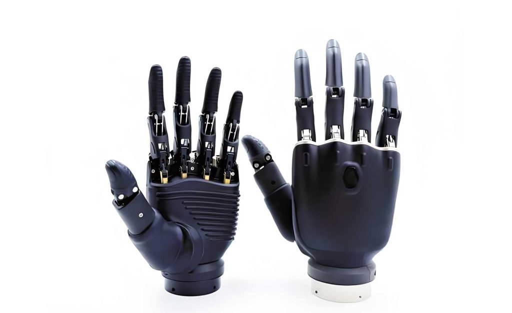
Following the determination of the finger count, the joint type for each finger must be specified. The two fundamental joint types are prismatic (linear) and revolute (rotary). Considering the nature of fabric grasping—which often involves enveloping and pinching motions—and the desire for human-like manipulation, revolute joints are chosen. To maximize dexterity within the operational workspace, each finger is designed with four degrees of freedom (4-DOF). A key design feature is the orientation of the first joint axis (proximal) perpendicular to the axes of the subsequent three joints. This configuration allows each finger to achieve a high degree of spatial flexibility. All three fingers of the dexterous robotic hand are structurally identical, simplifying analysis, control, and manufacturing. The conceptual structure is shown in the figure above.
Kinematic Modeling Using the Denavit-Hartenberg Convention
Kinematic modeling is fundamental for controlling the dexterous robotic hand. It involves establishing the mathematical relationship between the joint variables (angles for revolute joints) and the position and orientation (pose) of the fingertip. This encompasses both forward and inverse kinematics. Forward kinematics computes the fingertip pose given the joint angles, while inverse kinematics solves for the required joint angles to achieve a desired fingertip pose.
Forward Kinematics Analysis
We analyze a single finger, as the other two are kinematically identical. The Denavit-Hartenberg (D-H) convention provides a systematic method to assign coordinate frames to each link and derive the transformation matrices between them. The D-H parameters for one finger of the dexterous robotic hand are defined as follows:
Where $a_i$ is the link length, $\alpha_i$ is the link twist, $d_i$ is the link offset, and $\theta_i$ is the joint angle. For this design, all joints are revolute, the first joint axis is perpendicular to the others ($\alpha_1 = 90^\circ$), and there are no link offsets ($d_i = 0$).
| Link $i$ | $\alpha_{i-1}$ (deg) | $a_{i-1}$ (mm) | $d_i$ (mm) | $\theta_i$ (deg, range) |
|---|---|---|---|---|
| 1 | 0 | 0 | 0 | $\theta_1$ (0–120) |
| 2 | -90 | $L_1=10$ | 0 | $\theta_2$ (0–90) |
| 3 | 0 | $L_2=200$ | 0 | $\theta_3$ (0–180) |
| 4 | 0 | $L_3=135$ | 0 | $\theta_4$ (0–180) |
The homogeneous transformation matrix ${^{i-1}T_i}$, which defines the frame of link $i$ relative to link $i-1$, is given by the standard D-H formula:
$$ {^{i-1}T_i} = \begin{bmatrix}
\cos\theta_i & -\sin\theta_i\cos\alpha_{i-1} & \sin\theta_i\sin\alpha_{i-1} & a_{i-1}\cos\theta_i\\
\sin\theta_i & \cos\theta_i\cos\alpha_{i-1} & -\cos\theta_i\sin\alpha_{i-1} & a_{i-1}\sin\theta_i\\
0 & \sin\alpha_{i-1} & \cos\alpha_{i-1} & d_i\\
0 & 0 & 0 & 1
\end{bmatrix} $$
Substituting the parameters from the table yields the individual transformation matrices:
$$ {^0T_1} = \begin{bmatrix}
\cos\theta_1 & -\sin\theta_1 & 0 & 0\\
\sin\theta_1 & \cos\theta_1 & 0 & 0\\
0 & 0 & 1 & 0\\
0 & 0 & 0 & 1
\end{bmatrix},\quad {^1T_2} = \begin{bmatrix}
\cos\theta_2 & -\sin\theta_2 & 0 & L_1\\
0 & 0 & 1 & 0\\
-\sin\theta_2 & -\cos\theta_2 & 0 & 0\\
0 & 0 & 0 & 1
\end{bmatrix} $$
$$ {^2T_3} = \begin{bmatrix}
\cos\theta_3 & -\sin\theta_3 & 0 & L_2\\
\sin\theta_3 & \cos\theta_3 & 0 & 0\\
0 & 0 & 1 & 0\\
0 & 0 & 0 & 1
\end{bmatrix},\quad {^3T_4} = \begin{bmatrix}
\cos\theta_4 & -\sin\theta_4 & 0 & L_3\\
\sin\theta_4 & \cos\theta_4 & 0 & 0\\
0 & 0 & 1 & 0\\
0 & 0 & 0 & 1
\end{bmatrix} $$
The complete forward kinematics transformation from the finger base (frame {0}) to the fingertip (frame {4}) is obtained by consecutive multiplication:
$$ {^0T_4} = {^0T_1} \cdot {^1T_2} \cdot {^2T_3} \cdot {^3T_4} $$
This results in:
$$ {^0T_4} = \begin{bmatrix}
n_x & o_x & a_x & p_x\\
n_y & o_y & a_y & p_y\\
n_z & o_z & a_z & p_z\\
0 & 0 & 0 & 1
\end{bmatrix} $$
Where the orientation vectors ($\hat{n}, \hat{o}, \hat{a}$) and the position vector $\vec{p}$ are functions of the joint angles. The position of the fingertip is particularly crucial for trajectory planning:
$$ p_x = L_3 c_{234} + L_2 c_{23} + L_1 c_2 $$
$$ p_y = L_3 s_{234} + L_2 s_{23} + L_1 s_2 $$
$$ p_z = 0 $$
Here, we use the shorthand notation $c_{23} = \cos(\theta_2+\theta_3)$, $s_{234} = \sin(\theta_2+\theta_3+\theta_4)$, etc. Note that $\theta_1$ governs the rotation of the entire finger about the base z-axis, affecting the $x$ and $y$ components in the full 3D formulation, but for a single finger’s planar motion in its own bending plane, the above $p_x$ and $p_y$ are defined relative to its local frame after the $\theta_1$ rotation. The full 3D position is derived from the complete ${^0T_4}$ matrix.
Inverse Kinematics Considerations
Inverse kinematics for this dexterous robotic hand finger involves solving the nonlinear trigonometric equations derived from the forward kinematics matrix for the joint angles $(\theta_1, \theta_2, \theta_3, \theta_4)$ given a desired fingertip pose. Due to the kinematic structure (a 4-DOF planar chain within its bending plane after the first joint), the inverse kinematics problem can be solved geometrically or algebraically. For a desired planar position $(p_x, p_y)$ in the finger’s bending plane (post-$\theta_1$ rotation), the problem reduces to solving for a 3-link planar arm. This often yields multiple solutions (elbow-up vs. elbow-down configurations), requiring the selection of the most appropriate one based on collision avoidance, joint limits, and energy minimization. The first joint angle $\theta_1$ is typically solved independently based on the desired approach direction towards the fabric. The closed-form solutions, while not derived in full here, are essential for real-time control of the dexterous robotic hand.
Cartesian Space Trajectory Planning for Coordinated Motion
Once the dexterous robotic hand is modeled kinematically, planning the motion of its fingers from an initial pose to a target grasping pose is the next critical step. For grasping tasks, it is often imperative that all fingers reach their respective contact points simultaneously and with a specified velocity profile to ensure stable acquisition. Trajectory planning in Cartesian (task) space is preferred when the path of the fingertip itself needs to be precisely controlled, such as moving in a straight line to avoid obstacles or approach the fabric at a specific angle.
We employ linear interpolation with parabolic blends for Cartesian space trajectory planning. This method generates a straight-line path between the start point $P_0$ and the end point $P_f$, while ensuring smooth transitions at the beginning and end by blending parabolic acceleration/deceleration phases with a constant velocity phase. This results in continuous position and velocity profiles, which are essential for stable control and reducing mechanical stress on the dexterous robotic hand.
Let the start pose be defined by position $\vec{P}_0 = (x_0, y_0, z_0)$ and orientation $\vec{O}_0 = (\alpha_0, \beta_0, \gamma_0)$ (e.g., Euler angles). The target pose is $\vec{P}_f = (x_f, y_f, z_f)$ and $\vec{O}_f = (\alpha_f, \beta_f, \gamma_f)$. The total linear distance $L$ and orientation change $\Omega$ are:
$$ L = \sqrt{(x_f – x_0)^2 + (y_f – y_0)^2 + (z_f – z_0)^2} $$
$$ \Delta\vec{O} = (\alpha_f – \alpha_0, \beta_f – \beta_0, \gamma_f – \gamma_0) $$
The trajectory is parameterized by a normalized time variable $\lambda(t)$, which goes from 0 to 1 over the total motion time $T$. The interpolated pose at time $t$ is:
$$ \vec{P}(t) = \vec{P}_0 + \lambda(t) (\vec{P}_f – \vec{P}_0) $$
$$ \vec{O}(t) = \vec{O}_0 + \lambda(t) \Delta\vec{O} $$
The function $\lambda(t)$ for the parabolic blend linear trajectory is defined by an acceleration $A$ and a cruise velocity $V$. The duration $T_b$ and displacement $L_b$ of each parabolic blend segment are:
$$ T_b = \frac{V}{A}, \quad L_b = \frac{1}{2} A T_b^2 = \frac{V^2}{2A} $$
The total motion time $T$ is:
$$ T = \begin{cases}
2\sqrt{\frac{L}{A}} & \text{if } L < 2L_b \text{ (no constant velocity phase)}\\
\frac{L}{V} + \frac{V}{A} & \text{if } L \ge 2L_b
\end{cases} $$
The normalized blend time $\lambda_b = T_b / T$ and blend distance $\Lambda_b = L_b / L$. The normalized trajectory function $\lambda(t’)$ where $t’ = t/T$ is:
$$
\lambda(t’) =
\begin{cases}
\frac{1}{2} \frac{A T^2}{L} t’^2 & 0 \le t’ \le \lambda_b\\
\frac{V T}{L} (t’ – \frac{T_b}{2T}) & \lambda_b < t’ \le 1-\lambda_b\\
1 – \frac{1}{2} \frac{A T^2}{L} (1 – t’)^2 & 1-\lambda_b < t’ \le 1
\end{cases}
$$
This planning algorithm ensures that each fingertip of the dexterous robotic hand follows a smooth, straight-line path to its target, which is critical for predictable and reliable interaction with delicate fabrics. The joint space trajectories are then obtained by applying the inverse kinematics solution at each interpolated Cartesian pose along the path.
Simulation and Analysis in Matlab Environment
To validate the design, kinematics, and trajectory planning of the dexterous robotic hand, a comprehensive simulation environment was developed in Matlab. The simulation serves multiple purposes: verifying the correctness of the D-H model, visualizing the finger’s reachable workspace, testing the trajectory planning algorithm, and analyzing the coordinated motion of three fingers for a sample fabric-grasping task.
Workspace Visualization
The forward kinematics equations were implemented in a Matlab function. By randomly sampling joint angles within their specified limits ($\theta_1: [0, 120^\circ]$, $\theta_2: [0, 90^\circ]$, $\theta_3: [0, 180^\circ]$, $\theta_4: [0, 180^\circ]$) using a Monte Carlo method, the set of all reachable fingertip positions was generated and plotted in 3D space. The resulting point cloud clearly shows the dexterous workspace of a single finger, which resembles a complex volumetric sector. This visualization confirms that the chosen link lengths and joint limits provide a sufficiently large and practical workspace for interacting with fabric lying on a surface within the robot’s reach.
Trajectory Simulation
The Cartesian linear interpolation algorithm with parabolic blends was coded. For a single finger, a sample trajectory was defined from an open, extended pose to a closed, pinching pose near a simulated fabric location. The simulation calculated the sequence of Cartesian poses $\vec{P}(t), \vec{O}(t)$ over time. The following key plots were generated:
- Position vs. Time: Graphs of $x(t)$, $y(t)$, $z(t)$ showing the smooth S-curve profile characteristic of the parabolic blend, with a linear central segment if the distance is long enough.
- Velocity vs. Time: The first derivative of the position, showing a trapezoidal profile (or triangular if $L < 2L_b$), confirming continuous velocity from zero to a maximum cruise value and back to zero.
- Joint Angle Trajectories: By applying inverse kinematics to each Cartesian pose along the path, the required joint angles $\theta_i(t)$ were computed and plotted. These curves are smooth and continuous, demonstrating the feasibility of tracking the Cartesian path within the joint limits of the dexterous robotic hand.
Three-Fingered Coordinated Grasping Simulation
The core of the simulation involved coordinating three identical fingers. The base positions of the fingers were arranged symmetrically (e.g., at 120-degree intervals) around a central workspace. A target fabric object was modeled as a simple geometric primitive (e.g., a sphere or a crumpled point cloud) at a known location. For each finger, a target grasp point on the object’s surface was selected to form a stable three-point grasp. Independent Cartesian trajectories were planned for each finger from their respective home positions to their target grasp points, with identical motion time $T$ to ensure synchronized arrival.
The simulation animated the simultaneous motion of all three fingers. The animation visually verified the collision-free paths (self-collision detection was a basic part of the check) and the successful, stable enclosure of the target object by the fingertips. The simulation also allowed for the analysis of force closure by computing the contact normals and evaluating the grasp quality metric based on the positions of the three contact points, confirming the fundamental stability of the three-fingered design for fabric grasping.
| Aspect | Parameter / Method | Simulation Outcome / Observation |
|---|---|---|
| Kinematics | D-H Parameters (Table 1), Forward Kinematics | Model verified: Fingertip position calculations match graphical model poses. Workspace is ample for task. |
| Trajectory Planning | Linear Interpolation with Parabolic Blends, $A=100 mm/s^2$, $V=50 mm/s$ | Smooth, continuous Cartesian and joint space trajectories generated. No discontinuities in velocity. |
| Coordination | Synchronized timing for 3 fingers, independent target points. | Fingers reach grasp points simultaneously. Animation shows stable three-point contact formation. |
| Grasp Stability | Geometric force closure analysis based on contact points. | The three non-colinear contact points generated by the dexterous robotic hand confirm force closure in the plane. |
Discussion and Conclusion
The modeling and simulation study presented herein demonstrates a viable approach to designing and evaluating a dexterous robotic hand for automating fabric manipulation. The systematic process—from determining the optimal three-fingered structure based on stability requirements, through rigorous kinematic modeling using the D-H convention, to implementing smooth Cartesian trajectory planning—provides a solid foundation for control system development.
The Matlab simulation environment proved to be an effective tool for validating the conceptual design without physical prototyping. It confirmed that the selected link lengths and joint ranges produce a functional workspace. More importantly, it verified that the proposed straight-line path planning algorithm with parabolic blends generates trajectories that are not only smooth but also kinematically feasible for the dexterous robotic hand to execute. The coordinated motion simulation of three fingers successfully illustrated the core grasping sequence, visually affirming the stability inherent in the three-point contact strategy.
This work primarily addresses the kinematic and geometric aspects of control. The next critical layer for reliable fabric grasping involves dexterous robotic hand force control and tactile sensing. Flexible fabrics require compliant and adaptive grip forces to prevent slippage without causing damage or deformation. Integrating force/torque sensors at the wrist or tactile sensor arrays on the fingertips would enable impedance or hybrid force/position control strategies. Furthermore, advanced grasp planning algorithms that consider the deformable nature of fabric, potentially using vision-based feedback to estimate shape and select optimal grasp points, are essential for robust autonomous operation.
In conclusion, the comprehensive modeling, trajectory planning, and simulation framework establishes that a properly designed three-fingered dexterous robotic hand is kinematically capable of performing the delicate task of flexible fabric grasping. The results indicate reasonable structural design, accurate and reliable modeling, and satisfactory trajectory planning performance. This foundational research paves the way for the development of advanced robotic end-effectors that can seamlessly integrate into fully automated textile and apparel manufacturing systems, ultimately achieving the goal of a continuous, intelligent production chain.