
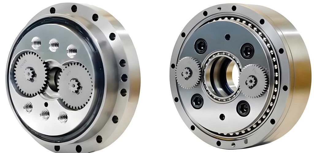
As a researcher focused on precision transmission systems, I have dedicated significant effort to improving the performance of robotic components. The Rotary Vector (RV) reducer, a core component in industrial robots, exemplifies the challenge of balancing high transmission accuracy with operational robustness. This two-stage closed differential gear train, evolved from cycloidal-pin gear planetary drives, is prized for its high reduction ratio, exceptional torsional stiffness, and smooth motion. However, its transmission precision, crucial for robotic positioning accuracy, is fundamentally governed by the design and manufacturing of its central component: the cycloidal gear. In its ideal theoretical form, a standard cycloidal gear meshes with needle teeth without backlash, but this state is impractical. It offers no compensation for manufacturing errors, assembly deformations, or thermal effects, leading to difficulties in assembly, poor lubrication, and potentially high contact stresses. Therefore, deliberate modification of the cycloidal gear tooth profile is not merely an option but a necessity for functional RV reducers.
The prevailing engineering practice often approaches this modification with a single objective in mind, typically minimizing transmission error or achieving a specific backlash. Some studies combine objectives through weighted sums. However, from my practical experience, this simplification fails to capture the inherent nonlinear trade-offs in real-world engineering. Optimizing for minimal transmission error might inadvertently increase backlash to unacceptable levels, and vice-versa. A true multi-objective optimization framework is required to navigate this design space effectively and find a set of optimal compromises, or Pareto-optimal solutions. This study presents my work on establishing such a framework. I developed mathematical models for backlash and transmission error as functions of modification parameters, implemented an enhanced Multi-Objective Particle Swarm Optimization (MOPSO) algorithm to explore the trade-offs, and validated the optimized profile through dynamic simulation.
Mathematical Modeling of Modification and Its Effects
Tooth Profile Equation for Modified Cycloidal Gear
The standard cycloidal profile is generated by a rolling circle. Modification is applied during the grinding process by altering the tool path or size. The two primary and most practical methods are:
- Offset Modification (Δrrp): Increasing the effective grinding wheel radius, creating uniform clearance around each needle tooth.
- Move Distance Modification (Δrp): Translating the grinding wheel radially inward, effectively reducing the generating circle radius.
A combined modification utilizing both methods simultaneously offers greater control over the final meshing characteristics. The parametric equations for the tooth profile after combined modification are given by:
$$
\begin{aligned}
x &= \left[ (r_p + \Delta r_p) – (r_{rp} + \Delta r_{rp}) \cdot S^{-1/2} \right] \cos[(1-i)\varphi] – \frac{a}{r_p + \Delta r_p} \left[ r_p + \Delta r_p – z_p (r_{rp} + \Delta r_{rp}) S^{-1/2} \right] \cos(i\varphi) \\
y &= \left[ (r_p + \Delta r_p) – (r_{rp} + \Delta r_{rp}) \cdot S^{-1/2} \right] \sin[(1-i)\varphi] – \frac{a}{r_p + \Delta r_p} \left[ r_p + \Delta r_p – z_p (r_{rp} + \Delta r_{rp}) S^{-1/2} \right] \sin(i\varphi)
\end{aligned}
$$
where the intermediate term \( S \) is defined as:
$$
S = 1 + k_1^2 – 2k_1 \cos(\varphi), \quad \text{with } k_1 = \frac{a z_p}{r_p}, \quad i = \frac{z_p}{z_c}
$$
Here, \( r_p \) is the needle tooth distribution radius, \( r_{rp} \) is the needle tooth radius, \( z_p \) and \( z_c \) are the numbers of needle teeth and cycloidal gear teeth respectively, \( a \) is the eccentricity, \( \varphi \) is the generating angle, and \( \Delta r_p \) and \( \Delta r_{rp} \) are the move distance and offset modification amounts, the key design variables in this study.
Analysis of Backlash Induced by Modification
Backlash, the lost motion during direction reversal, is critical for the positioning repeatability of a robot joint driven by an RV reducer. Modification intentionally introduces clearance, which directly translates to backlash. The contributions from each modification type can be derived geometrically.
Offset Modification (Δrrp): This creates a radial gap. To achieve contact, the cycloidal gear must rotate through a small angle \( \gamma \). Considering both forward and reverse directions, the total backlash contribution is:
$$
\Delta \phi_1 = \frac{2 \Delta r_{rp}}{a z_c}
$$
Move Distance Modification (Δrp): This effectively changes the center distance. Its contribution to the angular backlash is:
$$
\Delta \phi_2 = -\frac{2 \Delta r_p \cdot k_1^2}{a z_c}
$$
Therefore, the total nominal backlash \( \Delta \phi_b \) resulting from the combined modification is the sum:
$$
\Delta \phi_b = 2(|\Delta \phi_1| + |\Delta \phi_2|) = \frac{2}{a z_c} ( |\Delta r_{rp}| + |\Delta r_p| \cdot k_1^2 )
$$
This equation establishes a clear, linear relationship between the modification parameters and one of our target objectives: minimizing backlash.
Analysis of Transmission Error Using Tooth Contact Analysis (TCA)
Transmission Error (TE) is the deviation of the actual output position from the theoretically ideal position, a key metric for smoothness and accuracy. I employed the Tooth Contact Analysis method to model TE for the modified RV reducer. TCA involves solving for the kinematic relationship enforced by contact between the mating profiles.
Coordinate systems are attached to the cycloidal gear (\( S_c \)), the needle gear (\( S_p \)), and the fixed frame (\( S_f \)). The transformation matrix from \( S_c \) to \( S_f \) is:
$$
M_{f,c} =
\begin{bmatrix}
\cos \phi_2 & \sin \phi_2 & 0 & a \cos \phi_1 \\
-\sin \phi_2 & \cos \phi_2 & 0 & a \sin \phi_1 \\
0 & 0 & 1 & 0 \\
0 & 0 & 0 & 1
\end{bmatrix}
$$
where \( \phi_1 \) is the input crank angle and \( \phi_2 \) is the rotation of the cycloidal gear.
The conditions for continuous contact are: (1) the position vectors of the contact point on both gears coincide in the fixed frame, and (2) the unit normal vectors at the contact point are collinear. The surface coordinates and normals for the modified cycloid \( \mathbf{R_c} \) and the needle tooth \( \mathbf{R_p} \) are derived. After transformation to \( S_f \), the TCA equations are:
$$
\begin{cases}
\mathbf{^f r_p}(\beta) = \mathbf{^f r_c}(\phi_1, \phi_2, \phi_{TC}) \\
\mathbf{^f n_p}(\beta) = \mathbf{^f n_c}(\phi_1, \phi_2, \phi_{TC})
\end{cases}
$$
This system contains three unknowns: \( \phi_2 \), \( \phi_{TC} \) (the cycloid profile parameter), and \( \beta \) (the needle contact angle). For a given input angle \( \phi_1 \) and a set of modification parameters \( (\Delta r_p, \Delta r_{rp}) \), the system can be solved numerically to find the actual output \( \phi_2 \). The Transmission Error \( \Delta \phi_{TE} \) is then calculated as:
$$
\Delta \phi_{TE} = \phi_2 – \frac{\phi_1}{i_{total}}
$$
where \( i_{total} \) is the total reduction ratio of the RV reducer. By evaluating this over a full mesh cycle, the peak-to-peak transmission error can be determined, forming our second objective: minimizing \( \max(|\Delta \phi_{TE}|) \).
Multi-Objective Optimization Framework
With the two performance metrics mathematically defined as functions of the modification amounts, the design problem can be formally stated as a multi-objective optimization.
Objective Functions and Constraints
The goal is to find the Pareto-optimal set of modification parameters that best balance the conflict between low backlash and low transmission error.
Decision Variables:
$$
\mathbf{x} = [\Delta r_p, \quad \Delta r_{rp}]^T
$$
Objective Functions (to be minimized):
$$
\begin{aligned}
f_1(\mathbf{x}) &= \Delta \phi_b(\mathbf{x}) = \frac{2}{a z_c} ( |\Delta r_{rp}| + |\Delta r_p| \cdot k_1^2 ) \\
f_2(\mathbf{x}) &= \max(|\Delta \phi_{TE}(\mathbf{x})|)
\end{aligned}
$$
Constraints: Practical manufacturing and assembly limits must be considered.
$$
\begin{aligned}
& -0.05 \text{ mm} \leq \Delta r_p \leq 0.0 \text{ mm} \quad \text{(Typically negative for clearance)} \\
& 0.0 \text{ mm} \leq \Delta r_{rp} \leq 0.02 \text{ mm} \\
& \Delta r = |\Delta r_{rp}| + |\Delta r_p| \cdot (1 + k_1) \approx 0.01 – 0.10 \text{ mm} \quad \text{(Total radial clearance)}
\end{aligned}
$$
Improved Multi-Objective Particle Swarm Optimization (MOPSO)
The standard MOPSO algorithm is effective but can suffer from premature convergence or poor distribution of solutions along the Pareto front. To enhance its performance for this specific engineering problem, I introduced two modifications.
1. Exponential Nonlinear Decreasing Inertia Weight: Instead of a linear decrease, an exponential strategy provides a more aggressive search in early iterations and finer tuning later.
$$
\omega’ = \omega_0 + \frac{2 r_4}{3} (1 – \omega_0)^{iter / iter_{max}}
$$
where \( \omega_0 \) is the initial weight, \( r_4 \) is a random number in [0,1], \( iter \) is the current iteration, and \( iter_{max} \) is the maximum iteration.
2. Iteratively Updated Learning Factors: The cognitive (\( c_1 \)) and social (\( c_2 \)) factors are varied to shift emphasis from individual to social learning over time.
$$
\begin{aligned}
c_1 &= c_{1min} + (c_{1max} – c_{1min}) \cdot \frac{iter^2}{iter_{max}^2} \\
c_2 &= c_{2min} + (c_{2max} – c_{2min}) \cdot \frac{iter^2}{iter_{max}^2}
\end{aligned}
$$
The enhanced velocity and position update equations become:
$$
\begin{aligned}
\mathbf{v}_i^{new} &= \omega’ \mathbf{v}_i + c_1 r_1 (\mathbf{pbest}_i – \mathbf{x}_i) + c_2 r_2 (\mathbf{gbest} – \mathbf{x}_i) \\
\mathbf{x}_i^{new} &= \mathbf{x}_i + \mathbf{v}_i^{new}
\end{aligned}
$$
An external archive maintains the non-dominated solutions found during the search. The performance of this improved algorithm was first verified on standard test functions (ZDT1, ZDT2), showing better convergence and coverage of the true Pareto front compared to the standard version.
Optimization Results and Selection
The improved MOPSO was applied to the RV reducer modification problem with a population of 200 for 200 generations. The algorithm successfully generated a well-distributed Pareto front, illustrating the trade-off: reducing transmission error generally requires accepting slightly higher backlash. To select a single optimal compromise from the Pareto set for implementation, a fuzzy membership function was employed. This function assigns a satisfaction degree between 0 and 1 for each objective for every solution. The solution with the highest overall membership value is chosen.
| Solution | Δrp (mm) | Δrrp (mm) | Backlash, f1 (arc-min) | Trans. Error, f2 (arc-sec) | Membership Value, Φ |
|---|---|---|---|---|---|
| 1 | -0.048 | 0.018 | 0.22 | 20.1 | 0.75 |
| 2 | -0.052 | 0.015 | 0.20 | 21.5 | 0.82 |
| 3 | -0.054 | 0.019 | 0.19 | 22.5 | 0.88 |
| 4 | -0.0542 | 0.0192 | 0.188 | 22.2 | 0.92 |
| 5 | -0.058 | 0.012 | 0.17 | 24.8 | 0.79 |
As shown in Table 1, Solution #4 was selected as the final optimal compromise, with modification amounts \( \Delta r_p = -0.0542 \) mm and \( \Delta r_{rp} = +0.0192 \) mm. The resulting tooth profile closely follows the offset-modified shape in the working region, ensuring good conjugate action while providing the necessary clearance.
Simulation Verification and Comparative Analysis
To validate the performance of the optimized modification design, a detailed multi-body dynamics model of the complete RV reducer was built using a commercial software (Adams). The 3D components, including the cycloidal gear with the optimized profile, were modeled, and appropriate joints and contacts were defined.
| Component 1 | Component 2 | Joint Type |
|---|---|---|
| Input Shaft | Planet Carrier (Crank) | Revolute |
| Planet Gear | Planet Carrier | Revolute |
| Planet Carrier | Ground | Fixed |
| Crankshaft | Planet Gear | Revolute |
| Crankshaft | Cycloidal Gear | Revolute |
| Needle Gear Shell | Ground | Fixed |
| Output Disk | Cycloidal Gear | Fixed |
Backlash Simulation
Backlash was measured by applying a bidirectional step motion to the input. The output rotation was recorded, and the lost motion during reversal was calculated. Simulations were run for four different modification scenarios for comparison. The results, shown in Figure X (simulated data plot), clearly demonstrate that the optimized combined modification yields a lower backlash than single-method modifications.
| Modification Method | Δrp (mm) | Δrrp (mm) | Simulated Backlash (arc-min) |
|---|---|---|---|
| Standard (Theoretical) Profile | 0.0 | 0.0 | ~0.0 |
| Offset Only | 0.0 | 0.127 | 0.04 |
| Move Distance Only | -0.127 | 0.0 | 0.06 |
| Optimized Combined (This Study) | -0.0542 | 0.0192 | 0.018 |
The simulated backlash for the optimized profile was 0.018 arc-min, closely matching the theoretical prediction of 0.0188 arc-min from the model. It represents a reduction of 0.022 arc-min (55%) compared to the offset-only modification and 0.042 arc-min (70%) compared to the move-distance-only modification.
Transmission Error Simulation
Transmission error was evaluated by driving the input at a constant speed and measuring the instantaneous output speed. The theoretical output speed was calculated based on the reduction ratio, and the difference was integrated over time to obtain the positional transmission error. The peak-to-peak value was extracted.
| Modification Method | Peak-to-Peak Transmission Error (arc-seconds) | Reduction vs. Single Method |
|---|---|---|
| Standard Profile | 27.6 | – |
| Offset Only | 24.1 | Base |
| Move Distance Only | 24.4 | Base |
| Optimized Combined (This Study) | 22.5 | 6.6% (vs. Offset), 7.8% (vs. Move) |
The optimized profile achieved a peak-to-peak transmission error of 22.5 arc-seconds, which is in excellent agreement with the TCA model prediction of 22.2 arc-seconds. This represents a 6.6% improvement over the offset-only modification and a 7.8% improvement over the move-distance-only modification. The standard, unmodified profile exhibited the highest error due to the simulated effects of minor misalignments and deformations, which the modified profiles can compensate for.
Conclusion
In this study, I addressed the critical design challenge of cycloidal gear modification for high-performance RV reducers by developing and applying a comprehensive multi-objective optimization framework. The core contributions are threefold. First, I established precise mathematical models linking the key modification parameters (offset and move distance) to the two primary performance indicators: backlash and transmission error. The backlash model provides a direct analytical relationship, while the transmission error model employs a robust Tooth Contact Analysis (TCA) method suitable for modified profiles. Second, recognizing the limitations of single-objective or weighted-sum approaches, I implemented an enhanced Multi-Objective Particle Swarm Optimization algorithm. The introduced exponential inertia weight and adaptive learning factors improved the algorithm’s ability to explore the design space and find a well-distributed set of Pareto-optimal solutions, effectively mapping the trade-off between the conflicting objectives. Third, the selected optimal solution from the Pareto front was rigorously validated through dynamic multi-body simulation. The results conclusively demonstrate that the proposed optimized combined modification strategy outperforms traditional single-method modifications. Specifically, for the studied RV reducer configuration, the optimized profile simultaneously reduced backlash by 55-70% and peak-to-peak transmission error by 6.6-7.8% compared to using only offset or move-distance modification, respectively. This work provides a practical and effective methodology for the integrated design of cycloidal gear profiles, enabling the development of RV reducers with superior overall transmission performance, which is essential for advancing the precision and reliability of industrial robotics.