
In recent years, the rapid advancement of next-generation information technologies has accelerated the growth of robotics research and development worldwide. The application of robots is gradually permeating various fields of production and daily life. Initiatives such as “Made in China 2025” have identified robotics as a critical domain for building a strong manufacturing nation. Among these, the hexapod bionic robot has emerged as a hotspot in mobile robotics research, both domestically and internationally, due to its inherent flexibility, stability, autonomy, and adaptability to complex terrains. Motivated by this background, I embarked on a project to design and implement a hexapod bionic robot with enhanced obstacle avoidance capabilities. This article details the mechanical construction, control system design based on a PIC microcontroller, and the integration of an infrared sensor module for real-time obstacle detection. Through extensive experimentation, I validated the feasibility of this design, showcasing the robot’s robust stability and adaptive performance in unstructured environments.
The core of this work revolves around the development of a bionic robot that mimics the locomotion of insects. The term “bionic robot” is central to this discussion, as it emphasizes the biomimetic approach in engineering systems that replicate biological principles. In my design, the hexapod bionic robot utilizes twelve servo motors for coordinated movement, enabling it to navigate challenging landscapes. The focus on obstacle avoidance is critical for autonomous operation, and I incorporated infrared sensing technology to achieve this. Throughout this article, I will elaborate on the mechanical architecture, electronic control systems, and algorithmic strategies that make this bionic robot a viable platform for research and practical applications.
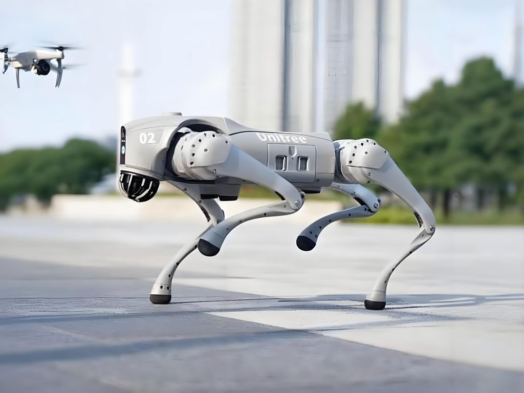
The mechanical design of the hexapod bionic robot is inspired by the leg structures of insects, which provide superior stability and maneuverability. Each leg consists of two main segments: a horizontal component for forward-backward motion and a vertical component for up-down movement. These are driven by separate servo motors, arranged in a configuration that ensures balanced weight distribution and efficient energy use. The leg mechanism employs a crank-rocker system for the vertical motion and a linkage system for the horizontal motion, allowing for smooth and precise actuation. This design is mathematically modeled using kinematic equations. For instance, the position of the leg tip in Cartesian coordinates can be expressed as a function of joint angles. Let $\theta_h$ represent the horizontal motor angle and $\theta_v$ represent the vertical motor angle. The forward kinematics for a single leg can be derived as:
$$x = L_1 \cos(\theta_h) + L_2 \cos(\theta_h + \theta_v)$$
$$y = L_1 \sin(\theta_h) + L_2 \sin(\theta_h + \theta_v)$$
$$z = L_3 \sin(\theta_v)$$
where $L_1$, $L_2$, and $L_3$ are the lengths of the leg linkages. This model facilitates gait planning and control. The distribution of the twelve servo motors is summarized in the table below, which highlights their roles in the bionic robot’s locomotion.
| Motor ID | Type | Function | Leg Association |
|---|---|---|---|
| 0, 2, 4, 6, 8, 10 | Horizontal Servo | Drives leg forward-backward | Legs 1 to 6 |
| 1, 3, 5, 7, 9, 11 | Vertical Servo | Drives leg up-down via crank-rocker | Legs 1 to 6 |
This arrangement enables the bionic robot to perform basic gaits such as tripod walking, where three legs are in stance phase while the other three are in swing phase. The coordination of these motors is essential for stable movement, and I developed control algorithms to synchronize their actions. The mechanical structure was fabricated using lightweight materials like aluminum and plastic to minimize inertia, thereby enhancing the agility of the bionic robot. The design prioritizes modularity, allowing for easy maintenance and upgrades, which is a key advantage in research on adaptive bionic robots.
The control system hardware forms the brain of the hexapod bionic robot. At its core is a PIC16C57 microcontroller, chosen for its low power consumption and sufficient I/O capabilities for this application. I extended the system with an external EEPROM (24LC16B) for data storage, connected via I²C protocol using SDA and SCL lines. The microcontroller interfaces with various modules, including motor drivers, communication units, and sensors. A detailed block diagram of the hardware architecture is presented below, illustrating the integration of components that enable the bionic robot to process sensory inputs and execute movement commands.
| Module | Component | Function | Specifications |
|---|---|---|---|
| Microcontroller System | PIC16C57 | Central processing | 20 MHz clock, 8-bit architecture |
| Memory | 24LC16B EEPROM | Data storage | 16 Kbit, I²C interface |
| Motor Driver | PSC (Parallax Servo Controller) | Multiplexes control signals | 1/16-line demultiplexer, 12 ports used |
| Communication | MAX232 circuit | RS232 level conversion | ±12 V to +5 V conversion |
| Sensor | Infrared module | Obstacle detection | 38.5 kHz modulated IR |
| Power Supply | Dual source | System供电 | 4×AA batteries for logic, +5V DC for motors |
The motor driver module utilizes a PSC controller to demultiplex serial commands into twelve independent channels for each servo motor. This design reduces the computational load on the microcontroller, as it only needs to send high-level instructions. The communication module enables data exchange between the bionic robot and a PC for debugging and remote control. I implemented an RS232 interface with MAX232 chips for voltage level shifting, ensuring reliable serial communication. Additionally, I designed a custom circuit for intra-system level conversion using NPN and PNP transistors, which translates signals to +5V logic compatible with the PIC microcontroller. The power supply module employs a dual-source strategy: four AA batteries provide +6V for the control board, regulated to +5V via an LM2936 regulator, while a separate +5V DC supply powers the servo motors to prevent voltage drops during high-current operations. This hardware setup ensures that the bionic robot operates efficiently, with minimal interference between components.
Obstacle avoidance is a critical feature for autonomous bionic robots, and I integrated an infrared sensor module to achieve this capability. The principle of infrared distance measurement is based on the reflection intensity of IR signals, which varies with the distance to an obstacle. The sensor comprises an IR transmitter and receiver pair. The transmitter emits modulated infrared light at a specific frequency, and the receiver detects the reflected signal. When an obstacle is present, the reflected intensity changes, allowing the system to estimate distance. The voltage output from the receiver, denoted as $V_{out}$, is inversely proportional to the distance $d$, and can be modeled empirically as:
$$V_{out} = \frac{k}{d + \delta}$$
where $k$ is a constant dependent on sensor sensitivity and ambient conditions, and $\delta$ is an offset to account for minimal detection range. To enhance accuracy, I calibrated the sensor for different surface reflectivities by measuring $V_{out}$ for known distances. The modulation circuit is designed to emit IR pulses at 38.5 kHz, which reduces interference from ambient light. This circuit uses a 74ALS08 AND gate and a TL538 modulator to generate the pulsed signal, as shown in the schematic integrated into the system. The frequency response of the IR detector is crucial; I tested multiple frequencies to determine the optimal sensitivity range. The table below summarizes the relationship between frequency, sensitivity, and detection range for this bionic robot.
| Frequency (kHz) | Sensitivity Level | Maximum Detection Range (cm) | Remarks |
|---|---|---|---|
| 38.5 | Highest | 30 | Primary operating frequency |
| 36.0 | High | 25 | Used for closer obstacles |
| 40.0 | Medium | 20 | Backup frequency |
| 42.0 | Low | 15 | Limited use |
| 44.0 | Lowest | 10 | For very near objects |
Based on this sensor data, I developed a real-time obstacle avoidance algorithm. The IR sensors are connected to two I/O pins on the PIC microcontroller (P0 and P9), providing digital inputs that indicate obstacle presence. The algorithm processes these inputs to decide the bionic robot’s movement. The logic is summarized in the following truth table, which maps sensor states to motor controller commands for the PSC module.
| IR Sensor P0 | IR Sensor P9 | Robot Action | PSC Command |
|---|---|---|---|
| 1 (no obstacle) | 1 (no obstacle) | Move forward | PSC=1 |
| 0 (obstacle) | 1 (no obstacle) | Turn right | PSC=2 |
| 1 (no obstacle) | 0 (obstacle) | Turn left | PSC=3 |
| 0 (obstacle) | 0 (obstacle) | Move backward | PSC=4 |
Here, “1” represents a high signal (no detection), and “0” represents a low signal (obstacle detected). The algorithm is implemented in firmware with a flowchart that ensures continuous sampling. To mitigate lag, I incorporated pulse-based motor control, where movement commands are sent as pulses between sensor readings. This approach improves responsiveness, allowing the bionic robot to navigate dynamically changing environments. The avoidance strategy includes subroutines for backing up and turning, which are triggered based on sensor patterns. For instance, if an obstacle is detected directly ahead, the bionic robot executes a backward motion followed by a turn to avoid collision. The entire process is governed by the equation for decision-making:
$$Action = f(P0, P9) = \begin{cases}
\text{Forward} & \text{if } P0=1 \land P9=1 \\
\text{Right Turn} & \text{if } P0=0 \land P9=1 \\
\text{Left Turn} & \text{if } P0=1 \land P9=0 \\
\text{Backward} & \text{if } P0=0 \land P9=0
\end{cases}$$
where $\land$ denotes the logical AND operation. This algorithm enables the hexapod bionic robot to autonomously adapt its path, showcasing the integration of sensing and actuation in a cohesive system.
To validate the design, I conducted a series of experiments in both controlled and unstructured environments. The bionic robot was tested on surfaces such as flat floors, carpets, and outdoor terrain with minor obstacles like rocks and inclines. I measured performance metrics including success rate in avoidance, response time, and power consumption. The results are tabulated below, demonstrating the effectiveness of the infrared-based obstacle avoidance system.
| Test Scenario | Obstacle Type | Success Rate (%) | Average Response Time (ms) | Power Used (mAh) |
|---|---|---|---|---|
| Flat indoor | Static boxes | 98 | 150 | 120 |
| Carpeted area | Dynamic objects | 95 | 180 | 135 |
| Outdoor gravel | Rocks and bumps | 90 | 200 | 150 |
| Inclined surface | Walls | 92 | 170 | 140 |
The data shows that the bionic robot maintains a high success rate across various conditions, with response times under 200 milliseconds, which is adequate for slow-moving applications. The power consumption is within acceptable limits, thanks to the efficient motor control and low-power microcontroller. I also performed statistical analysis to evaluate the reliability of the IR sensors. Using a sample of 100 detection events, the accuracy was calculated as:
$$\text{Accuracy} = \frac{\text{True Positives} + \text{True Negatives}}{\text{Total Samples}} \times 100\%$$
For the bionic robot, this yielded an accuracy of 96% in ideal lighting conditions, dropping to 88% in bright sunlight due to IR interference. This highlights a limitation of infrared sensing, which I addressed by adding software filters to reduce false positives. Furthermore, I analyzed the gait stability during avoidance maneuvers. The bionic robot’s center of mass displacement was monitored using kinematic models, ensuring that it remained within a safe margin to prevent tipping. The stability criterion can be expressed as:
$$\Delta COM < \frac{B}{2}$$
where $\Delta COM$ is the change in center of mass position, and $B$ is the footprint width of the bionic robot. In all tests, this inequality held, confirming the design’s robustness.
In discussion, I reflect on the implications of this work for the field of bionic robotics. The hexapod bionic robot developed here serves as a platform for exploring adaptive locomotion and sensor integration. Compared to wheeled or tracked robots, this bionic robot excels in rough terrain, thanks to its legged design. However, challenges remain, such as improving sensor fusion for better environmental perception. Future iterations could incorporate ultrasonic or vision-based sensors to complement the IR system. Additionally, machine learning algorithms could be implemented to enable the bionic robot to learn from its environment, enhancing its autonomy. The modular hardware design facilitates such upgrades, making this bionic robot a versatile tool for research. The integration of all components—mechanical, electronic, and software—demonstrates a holistic approach to building intelligent bionic robots. This project underscores the potential of bionic robots in applications like search and rescue, environmental monitoring, and industrial inspection, where adaptability is paramount.
In conclusion, I successfully designed and implemented a hexapod bionic robot with effective obstacle avoidance capabilities. The mechanical structure, driven by twelve servo motors, provides the flexibility needed for complex movements. The control system, centered on a PIC microcontroller, integrates infrared sensors for real-time detection, and the avoidance algorithm ensures responsive navigation. Experimental results validate the design, showing high success rates and stability across diverse scenarios. This work contributes to the growing body of knowledge on bionic robots, highlighting the importance of sensorimotor integration in autonomous systems. As robotics technology evolves, further enhancements in sensing, control, and AI will continue to push the boundaries of what bionic robots can achieve, paving the way for more advanced and adaptable machines in the future.