
In the realm of high-precision transmission systems, such as those used in industrial robotics and CNC machine tools, the rotary vector reducer has emerged as a critical component due to its compact size, high load capacity, large transmission ratio, and superior efficiency. This type of reducer, often abbreviated as RV reducer, evolved from cycloidal pin wheel transmissions and represents a significant advancement in motion control technology. The complexity and variety of rotary vector reducer designs necessitate efficient modeling approaches to support modern engineering analyses like finite element analysis (FEA) and multibody dynamics simulation. In this article, I present a comprehensive methodology for three-dimensional parametric modeling and virtual assembly of a rotary vector reducer using Pro/ENGINEER (Pro/E) software, focusing on feature-based techniques that enable rapid design iterations and reduce reliance on physical prototypes.
The adoption of virtual prototyping technology allows engineers to create digital models that mimic the behavior of physical systems, facilitating performance evaluation and design optimization without the costs and time associated with building hardware. For the rotary vector reducer, which comes in numerous specifications and involves intricate moving parts, parametric modeling is particularly advantageous. By defining key geometric parameters as variables, one can generate entire families of reducer configurations with minimal effort. This approach not only streamlines the design process but also ensures consistency when integrating models into simulation environments like ANSYS for stress analysis or ADAMS for dynamic response studies. Throughout this discussion, I will emphasize the practical steps involved in constructing and validating a virtual prototype of a rotary vector reducer, highlighting how parameterization enhances flexibility and accuracy.
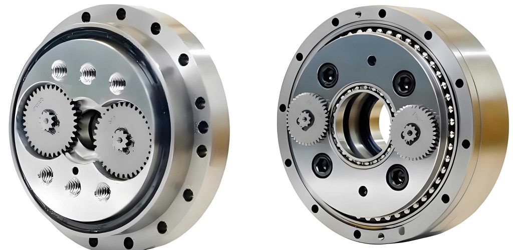
To begin the parametric modeling of a rotary vector reducer, it is essential to understand its fundamental transmission principle. The reducer typically consists of an input shaft, involute gears, crank shafts, cycloidal discs, an output plate, pin teeth, a pin gear housing, and various bearings. The motion is transferred through a two-stage process: the first stage involves involute gear meshing to reduce speed, while the second stage employs cycloidal pin engagement for further reduction and torque amplification. This dual-stage mechanism contributes to the high performance of the rotary vector reducer, but it also introduces modeling challenges due to the precise tooth profiles and assembly constraints. In the following sections, I will detail the parameterization of individual components, starting with the cycloidal disc, which is a core element of the rotary vector reducer.
Parametric Modeling of Cycloidal Disc
The cycloidal disc, responsible for the second-stage speed reduction in a rotary vector reducer, features a tooth profile derived from cycloidal equations. Each tooth is symmetric, allowing for efficient modeling by creating half a tooth profile and mirroring it to form a complete tooth, then arraying it circumferentially. In Pro/E, this is achieved by defining a set of characteristic parameters that control the geometry. The table below summarizes these parameters for a typical rotary vector reducer, such as the RV-40E model:
| Parameter | Example Value | Description |
|---|---|---|
| zg | 39 | Number of teeth on cycloidal disc |
| zb | 40 | Number of pin teeth |
| rz | 66 mm | Radius of pin tooth center circle |
| rrz | 3 mm | Radius of pin tooth |
| e | 1.5 mm | Eccentricity |
| m | 0 mm | Shift modification amount |
| n | 0 mm | Equidistant modification amount |
| k | Calculated | Short-width coefficient |
| a | Calculated | Rotation angle between crank and pin center |
These parameters are input into Pro/E’s parameter dialog, and relationships are established to compute dependent variables. For instance, the short-width coefficient k and angle a are derived using the following formulas, which are embedded in Pro/E’s relation editor:
$$ k = \frac{e \cdot z_b}{(r_z + m) / (z_b – z_g)} $$
$$ a = \frac{180}{z_g} $$
Once the parameters are set, the cycloidal tooth profile curve is generated via an equation-driven curve feature. In a Cartesian coordinate system, the parametric equations for the cycloid are defined as follows, where t is a Pro/E system variable ranging from 0 to 1:
$$ \text{ang} = a \cdot t $$
$$ p = \frac{k \cdot \sin(z_b \cdot \text{ang}) – \sin(\text{ang})}{\sqrt{1 + k^2 – 2k \cdot \cos(z_g \cdot \text{ang})}} $$
$$ q = \frac{-k \cdot \cos(z_b \cdot \text{ang}) + \cos(\text{ang})}{\sqrt{1 + k^2 – 2k \cdot \cos(z_g \cdot \text{ang})}} $$
$$ x = (r_z + m) \cdot \sin(\text{ang}) – e \cdot \sin(z_b \cdot \text{ang}) + (r_{rz} + n) \cdot p $$
$$ y = (r_z + m) \cdot \cos(\text{ang}) – e \cdot \cos(z_b \cdot \text{ang}) – (r_{rz} + n) \cdot q $$
$$ z = 0 $$
This creates half of a tooth profile, which is then mirrored across a reference plane to form a full tooth. A circular pattern is applied with an angle of \(360/z_g\) and an instance count of \(z_g\), resulting in the complete two-dimensional cycloidal disc profile. To parameterize the pattern, the angle and count are linked to the parameters through relations. Finally, the profile is extruded to a specified thickness (e.g., 10 mm) and features like bearing holes or shaft bores are added via extrusion cuts. The resulting three-dimensional model of the cycloidal disc adapts automatically when any of the characteristic parameters are modified, showcasing the power of parametric design for a rotary vector reducer.
Parametric Modeling of Involute Gear
The involute gear, part of the first reduction stage in a rotary vector reducer, is modeled using a similar parametric approach. The process involves creating a base circle, generating an involute curve, mirroring it to form a tooth profile, extruding it into a solid, and then arraying it around the gear axis. Key parameters for the involute gear are listed in the table below:
| Parameter | Example Value | Description |
|---|---|---|
| m | 1.5 mm | Module |
| z | 32 | Number of teeth |
| alpha | 20° | Pressure angle |
| hax | 1 | Addendum coefficient |
| cx | 0.25 | Dedendum coefficient |
| b | 7 mm | Gear width |
| ha | Calculated | Addendum height |
| hf | Calculated | Dedendum height |
| x | 0 | Profile shift coefficient |
| da | Calculated | Tip diameter |
| db | Calculated | Base diameter |
| df | Calculated | Root diameter |
| d | Calculated | Pitch diameter |
Relations are used to compute derived dimensions based on these parameters. For example, the addendum height ha, dedendum height hf, and diameters are calculated with the following equations:
$$ h_a = (h_{ax} + x) \cdot m $$
$$ h_f = (h_{ax} + c_x – x) \cdot m $$
$$ d = m \cdot z $$
$$ d_a = d + 2 \cdot h_a $$
$$ d_b = d \cdot \cos(\alpha) $$
$$ d_f = d – 2 \cdot h_f $$
In the sketching environment, four concentric circles representing the tip, pitch, root, and base circles are drawn with dimensions tied to these parameters. The involute curve is then created using parametric equations in a Cartesian coordinate system:
$$ \text{ang} = 90 \cdot t $$
$$ r = \frac{d_b}{2} $$
$$ s = \pi \cdot r \cdot t / 2 $$
$$ x_c = r \cdot \cos(\text{ang}) $$
$$ y_c = r \cdot \sin(\text{ang}) $$
$$ x = x_c + s \cdot \sin(\text{ang}) $$
$$ y = y_c – s \cdot \cos(\text{ang}) $$
$$ z = 0 $$
This curve is mirrored across a plane offset by \(360/(4z)\) degrees to form a symmetric tooth profile. Fillet radii at the tooth root are added with dimensions conditioned on the addendum coefficient; for instance, if \(h_{ax} \geq 1\), the fillet radius is set to \(0.38 \cdot m\). The resulting planar profile is extruded to the gear width, and a circular pattern with \(z\) instances completes the involute gear model. Like the cycloidal disc, this gear model is fully parametric, allowing quick adjustments for different rotary vector reducer specifications.
Parametric Modeling of Other Components
Additional parts of the rotary vector reducer, such as the input shaft, crank shaft, output plate, support disc, and bearings, are modeled using basic extrusion and revolution features in Pro/E. To maintain consistency for assembly, all sketches are oriented on standard reference planes—typically, extrusions are sketched on the FRONT plane and revolutions on the TOP plane—ensuring that the Z-axes of all parts align. Key dimensions for these components are also parameterized by adding them to relations. For simulation efficiency, some geometric details like chamfers, bolt holes, or complex spline connections can be simplified; for example, splines on the crank shaft may be replaced with simple cylinders since parts are often treated as rigid bodies in dynamics software. This simplification reduces computational load in subsequent analyses without compromising the functional integrity of the rotary vector reducer model.
Virtual Assembly of Rotary Vector Reducer
Assembly in Pro/E leverages the concept of parent-child relationships, where certain features or components depend on others for their placement and orientation. This is crucial for maintaining assembly constraints when parameters change. For the rotary vector reducer, a strategic assembly sequence is adopted to ensure robustness. First, a sub-assembly of pin teeth is created by patterning a single pin tooth around a circle; this sub-assembly is then imported into the main assembly and fixed as a default reference. Next, the primary moving components are added in the following order: output plate, crank shaft, cycloidal disc, involute gear, and input shaft. These are connected using pin joints to allow rotational motion for animation and simulation. The output plate, crank shaft, and input shaft are defined as pin joints, with the crank shaft childed to the output plate, and the cycloidal disc and involute gear childed to the crank shaft. To prevent gear interference during assembly, datum planes are created at the symmetry planes of gear teeth and aligned temporarily, then removed before motion definition. Constraints like “align” and “mate” are applied to position parts accurately.
After the core components are assembled, secondary parts such as the support disc, bearings, and pin gear housing are added. The support disc and main bearing are childed to the output plate, while crank bearings are childed to the crank shaft, and the pin gear housing is childed to the pin tooth sub-assembly. This hierarchical structure ensures that if any part’s parameters are modified, the entire assembly updates accordingly without losing constraints. The completed virtual assembly of the rotary vector reducer provides a fully parametric digital mock-up ready for export to analysis tools.
Validation of Parametric Model
To verify the correctness of the rotary vector reducer parametric model, a kinematic simulation is performed within Pro/E’s mechanism module. Before animation, an interference check is conducted to confirm no geometric clashes exist. Then, gear pairs are defined: one between the input shaft gear and the involute gear with a transmission ratio of 16:32 (based on tooth counts), and a hypothetical pair representing the cycloidal disc’s motion relative to the pins, with a ratio of 40:1 to account for the speed reduction in the second stage. A servo motor is applied to the input shaft, rotating it at 1500 rpm. A kinematic analysis runs the simulation, and the motion of all components is observed to ensure smooth operation. Finally, a velocity measurement on the output plate yields a speed of approximately 18.52 rpm, which matches the theoretical value calculated as \(1500 / 81 = 18.52\) rpm (since the total reduction ratio is 81:1 for this rotary vector reducer configuration). This agreement validates the accuracy of the parametric model, confirming that it faithfully represents the mechanical behavior of a physical rotary vector reducer.
Parametric Analysis of Rotary Vector Reducer
With a validated virtual prototype, various analyses can be conducted to study the performance of the rotary vector reducer. These analyses fall into three categories: pure kinematics, dynamics, and clearance studies, each offering insights into different aspects of reducer behavior.
Kinematic Analysis
In pure kinematic analysis, all joints are idealized as perfect constraints without considering forces or contacts. This approach is useful for visualizing motion patterns and verifying transmission ratios. For the rotary vector reducer, kinematic simulation demonstrates how input rotation propagates through the gears and cycloidal mechanism to produce output rotation, highlighting the motion coordination between stages. Since velocities are constant and no fluctuations occur, kinematics serves as a baseline for understanding the structural functionality of the rotary vector reducer.
Dynamic Analysis
Dynamic analysis incorporates material properties, masses, and contact forces to simulate real-world operating conditions. For the rotary vector reducer, this can be done in stages to isolate effects. First, by keeping the second stage as a kinematic pair and modeling the first-stage gear mesh as a contact pair, one can assess how gear啮合 forces influence output dynamics, such as torque ripple or vibration. Conversely, by modeling the cycloidal-pin contacts dynamically while keeping the first stage kinematic, the impact of the second stage on overall performance can be evaluated. Finally, a full dynamic model with both stages as contact pairs reveals coupled effects, providing a comprehensive view of the rotary vector reducer’s dynamic response under load. Such analyses are valuable for optimizing durability and efficiency.
Clearance Analysis
Clearance analysis focuses on the effects of manufacturing tolerances and intentional modifications, such as tooth profile corrections in the cycloidal disc. In the parametric model, this involves adjusting parameters like the shift modification amount m and equidistant modification amount n in the cycloidal equations. By varying these parameters and running dynamic simulations, one can study how clearances affect backlash, transmission error, and stress distribution in the rotary vector reducer. Similarly, modifications to other components, such as bearing fits or gear backlash, can be explored parametrically. This capability allows designers to tolerance specifications and improve the robustness of the rotary vector reducer design without physical testing.
Advantages and Applications
The parametric modeling and virtual assembly methodology described here offers several key benefits for developing rotary vector reducers. First, it significantly reduces repetitive modeling efforts across different reducer specifications, as changing a few parameters automatically regenerates the entire assembly. Second, it ensures assembly consistency through careful parent-child relationships, preventing misalignment when dimensions are updated. Third, the models are directly usable in advanced simulation software like ANSYS for finite element analysis or ADAMS for multibody dynamics, streamlining the workflow from design to validation. This integration is particularly important for complex systems like the rotary vector reducer, where performance depends on precise interactions between components. Additionally, the approach is accessible to engineers with basic Pro/E skills, avoiding the need for complex secondary development tools that require specialized programming knowledge.
In practical terms, this parametric framework supports a wide range of applications. For instance, in robotics, where rotary vector reducers are commonly used in joint actuators, designers can quickly adapt the model to different robot sizes or payload requirements. In academic research, the model facilitates studies on transmission accuracy, fatigue life, or noise reduction. Moreover, by coupling the parametric model with optimization algorithms, one can automate design explorations to find optimal parameters for specific performance criteria, such as minimizing weight while maximizing torque capacity. The flexibility and efficiency of this method make it a valuable tool in the ongoing advancement of rotary vector reducer technology.
Conclusion
In summary, this article has detailed a feature-based parametric modeling and virtual assembly strategy for rotary vector reducers using Pro/E software. By defining characteristic parameters and relationships for each component, such as the cycloidal disc and involute gear, and by structuring assembly constraints with appropriate parent-child dependencies, we have created a flexible digital prototype that adapts to design changes seamlessly. The model has been validated through kinematic simulation, confirming its accuracy in representing the transmission behavior of a rotary vector reducer. Furthermore, the parametric approach enables comprehensive analyses—including kinematics, dynamics, and clearance studies—that provide deep insights into reducer performance without the need for physical prototypes. This methodology not only accelerates the design cycle but also enhances the reliability and precision of rotary vector reducers, supporting their critical role in high-tech industries. As demand for efficient motion control grows, such parametric techniques will continue to be indispensable in the development of advanced rotary vector reducer systems.
To reiterate, the core strength of this approach lies in its simplicity and practicality. Engineers can implement it with standard CAD tools, avoiding complex programming, while still achieving a high degree of automation and integration with simulation platforms. Future work may involve extending the parametric model to include thermal effects or incorporating real-time sensor data for digital twin applications. Nonetheless, the foundation presented here offers a robust starting point for anyone engaged in the design and analysis of rotary vector reducers, empowering innovation in this vital field of mechanical engineering.