
In this comprehensive analysis, I delve into the intricate motion characteristics of the rotary vector reducer, a pivotal component in modern robotic joints. The rotary vector reducer, often abbreviated as RV reducer, exemplifies a sophisticated planetary closed differential system. My exploration begins by distinguishing between planetary differential mechanisms and planetary closed differential mechanisms, followed by a detailed examination of the rotary vector reducer’s evolution from one-tooth differential cycloid-pin drives. I introduce the concept of the crank shaft as a negative one-tooth sun gear, perform equivalent transmission ratio calculations, and derive power flow distribution formulas. This work aims to illuminate the underlying principles of planetary closed differential motion in rotary vector reducers, providing a foundation for forward design methodologies.
The rotary vector reducer has gained prominence due to its compact size, high stiffness, low backlash, wide transmission ratio range, and exceptional load-bearing capacity. Its application in industrial robot joints underscores its critical role in precision motion control. However, the design and manufacturing of rotary vector reducers remain dominated by a few companies, necessitating deeper independent research. Through this analysis, I seek to demystify the planetary closed differential nature of the rotary vector reducer, leveraging mathematical models and kinematic equivalences.
| Mechanism Type | Degrees of Freedom | Key Characteristics | Example Applications |
|---|---|---|---|
| Planetary Differential | 2 or more | Splits one input into multiple outputs based on load; open power flow. | Automotive differentials, NGW-type speed variators. |
| Planetary Closed Differential | 1 | Power flow splits and recombines within the mechanism; single output. | Wind turbine gearboxes (e.g., Rexroth, MAAG), rotary vector reducers. |
Planetary differential mechanisms, such as automotive differentials, possess two degrees of freedom, allowing motion division. In contrast, planetary closed differential mechanisms, like those in wind turbine gearboxes, have one degree of freedom and feature internal power splitting and recombination. The rotary vector reducer falls into the latter category, which is fundamental to its high performance.
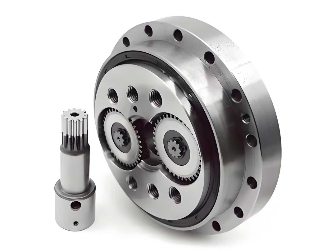
The structural evolution of the rotary vector reducer from a one-tooth differential cycloid-pin drive is pivotal. In the basic cycloid drive, a crank shaft inputs motion to a cycloid gear meshing with a fixed pin gear, yielding high reduction ratios. The rotary vector reducer enhances this by offsetting the crank shaft from the center, employing multiple crank shafts (typically 2-3), and adding a planetary gear stage. This modification reduces bearing loads and allows flexible ratio adjustment via the planetary gear teeth. The core innovation lies in treating the crank shaft as a planetary element with both rotation and revolution.
To analyze the transmission ratio, I employ an equivalent mechanism approach. For a one-tooth differential cycloid-pin drive, the crank shaft can be equivalently represented as a sun gear with negative one tooth. This analogy stems from the kinematic similarity to NGW planetary gears. In an NGW system with fixed ring gear, sun input, and carrier output, the ratio is:
$$ i_{\text{planetary}} = \frac{z_{\text{sun}} + z_{\text{ring}}}{z_{\text{sun}}} $$
Where \( z_{\text{sun}} \) and \( z_{\text{ring}} \) are tooth counts. For the cycloid drive, let \( z_5 = -1 \) represent the crank shaft (equivalent sun), \( z_3 \) be the cycloid gear teeth, and \( z_4 \) be the pin gear teeth. Since \( z_4 – z_3 = 1 \), the reduction ratio becomes:
$$ i_{\text{cycloid}} = \frac{z_5 + z_4}{z_5} = \frac{-1 + z_4}{-1} = -(z_4 – 1) = -z_3 $$
This negative sign indicates direction reversal, but magnitude-wise, it matches the known cycloid ratio. Extending to the rotary vector reducer, which combines a planetary stage (sun gear \( z_1 \), planet gear \( z_2 \), carrier \( H \)) with the cycloid stage (crank shaft as planet shaft), the overall ratio is derived from relative motion equations. Let \( n_1 \) be sun input speed, \( n_H \) carrier output speed, and \( n_4 = 0 \) fixed pin gear speed. The kinematic relation is:
$$ \frac{n_1 – n_H}{n_4 – n_H} = (-1) \cdot \frac{z_2}{z_1} \cdot (-1) \cdot \frac{z_3}{z_5} \cdot \frac{z_4}{z_3} $$
Simplifying with \( z_5 = -1 \) and \( z_4 = z_3 + 1 \), the total ratio for the rotary vector reducer is:
$$ i_{\text{RV}} = \frac{n_1}{n_H} = \frac{z_2}{z_1} \cdot z_4 + 1 $$
This formula highlights how the rotary vector reducer’s ratio depends on both planetary and cycloid stages, offering wide adjustability. The equivalence confirms the negative one-tooth sun concept’s validity for the rotary vector reducer.
The planetary closed differential motion of the rotary vector reducer is characterized by power flow splitting. I equivalent the system into two parallel paths: Path 1 transmits power directly from the planetary carrier to the output, while Path 2 routes power through the planetary gear mesh and cycloid stage before recombination at the carrier. This closed differential behavior ensures single-degree-of-freedom operation.
| Power Flow Path | Description | Transmission Ratio Contribution | Power Percentage Formula |
|---|---|---|---|
| Path 1 (Direct) | From sun gear through planets to carrier without cycloid stage. | \( i_1 = \frac{z_2}{z_1} + 1 \) | \( Q_1 = \frac{i_1}{i_{\text{RV}}} \) |
| Path 2 (Indirect) | From sun gear through planets, crank shafts, cycloid gears to carrier. | \( i_2 = \frac{z_2}{z_1} \cdot z_3 \) | \( Q_2 = \frac{i_2}{i_{\text{RV}}} \) |
The total ratio \( i_{\text{RV}} \) is the sum of the individual path ratios, a hallmark of planetary closed differential systems:
$$ i_{\text{RV}} = i_1 + i_2 = \left( \frac{z_2}{z_1} + 1 \right) + \left( \frac{z_2}{z_1} \cdot z_3 \right) = \frac{z_2}{z_1} \cdot (z_3 + 1) + 1 = \frac{z_2}{z_1} \cdot z_4 + 1 $$
The power distribution percentages are derived as follows, where \( P \) is total input power, \( P_1 \) and \( P_2 \) are powers in Paths 1 and 2, and \( Q_1 \), \( Q_2 \) are their fractions:
$$ Q_1 = \frac{P_1}{P} = \frac{i_1}{i_{\text{RV}}} = \frac{ \frac{z_2}{z_1} + 1 }{ \frac{z_2}{z_1} \cdot z_4 + 1 } $$
$$ Q_2 = \frac{P_2}{P} = \frac{i_2}{i_{\text{RV}}} = \frac{ \frac{z_2}{z_1} \cdot z_3 }{ \frac{z_2}{z_1} \cdot z_4 + 1 } $$
With \( Q_1 + Q_2 = 1 \). This distribution reveals that the cycloid gears do not transmit full power, reducing their load and enhancing durability. To verify, consider the tangential forces. For the planetary stage, sun gear radius \( r_1 \), planet gear radius \( r_2 \), and tangential force \( F_t \). The torque on the carrier from Path 1 is \( T = F_t \times (r_1 + r_2) \). The power via Path 1 is \( P_1 = F_t \times \omega_H \times (r_1 + r_2) \), where \( \omega_H = \omega_1 / i_{\text{RV}} \). Total input power is \( P = F_t \times \omega_1 \times r_1 \). Thus,
$$ \frac{P_1}{P} = \frac{ F_t \times \frac{\omega_1}{i_{\text{RV}}} \times (r_1 + r_2) }{ F_t \times \omega_1 \times r_1 } = \frac{r_1 + r_2}{r_1} \cdot \frac{1}{i_{\text{RV}}} = \frac{ \frac{z_2}{z_1} + 1 }{ \frac{z_2}{z_1} \cdot z_4 + 1 } $$
Matching the earlier formula. This consistency underscores the planetary closed differential nature of the rotary vector reducer.
Further analysis involves efficiency and load distribution. The rotary vector reducer’s closed differential design minimizes losses by balancing power across paths. Efficiency \( \eta \) can be modeled as a weighted sum of path efficiencies \( \eta_1 \) and \( \eta_2 \):
$$ \eta_{\text{RV}} = Q_1 \eta_1 + Q_2 \eta_2 $$
Typical values for well-lubricated rotary vector reducers exceed 90%, attributable to rolling contacts in cycloid meshes and optimized gear geometry. Load sharing among multiple crank shafts in the rotary vector reducer reduces stress concentrations. For \( N \) crank shafts, the load per crank shaft \( F_{\text{crank}} \) relates to total torque \( T_{\text{in}} \) and offset distance \( a \):
$$ F_{\text{crank}} = \frac{T_{\text{in}}}{N \cdot a} $$
This distribution is critical for high-torque applications, such as robotic arms, where the rotary vector reducer excels.
| Parameter | Symbol | Typical Range | Influence on Performance |
|---|---|---|---|
| Sun Gear Teeth | \( z_1 \) | 10-30 | Affects ratio and power split; smaller \( z_1 \) increases ratio. |
| Planet Gear Teeth | \( z_2 \) | 20-50 | Modulates ratio and load capacity. |
| Cycloid Gear Teeth | \( z_3 \) | 30-100 | Determines cycloid reduction; higher \( z_3 \) increases ratio. |
| Pin Gear Teeth | \( z_4 \) | \( z_3 + 1 \) | Fixed by one-tooth difference; ensures proper meshing. |
| Number of Crank Shafts | \( N \) | 2-3 | Improves load sharing; more shafts reduce bearing stress. |
| Offset Distance | \( a \) | 1-5 mm | Impacts cycloid motion and compactness. |
In forward design of rotary vector reducers, these parameters are optimized via kinematic and dynamic simulations. The planetary closed differential model aids in predicting behavior under varying loads. For instance, torque ripple can be minimized by selecting tooth counts that smooth power flow transitions. The rotary vector reducer’s stiffness, crucial for robotic precision, derives from the preloaded cycloid pins and gear meshes. Stiffness \( K \) approximates as:
$$ K \approx \frac{E \cdot A}{L} + \sum_{i} k_{\text{gear}, i} $$
Where \( E \) is Young’s modulus, \( A \) cross-sectional area, \( L \) length, and \( k_{\text{gear}, i} \) mesh stiffnesses. High stiffness in rotary vector reducers ensures minimal deflection under load.
Comparative studies with other reducers, like harmonic drives, highlight the rotary vector reducer’s advantages. Harmonic drives offer high ratios but suffer from fatigue in flex splines. In contrast, rotary vector reducers use rigid components, enhancing longevity. The planetary closed differential architecture allows the rotary vector reducer to achieve similar ratios with better load distribution. This makes the rotary vector reducer preferred for heavy-duty robotics.
Thermal management is another aspect. Power losses generate heat, affecting lubrication and wear. The efficiency formulas above help estimate heat dissipation. For a rotary vector reducer with input power \( P_{\text{in}} \), heat generation \( Q_{\text{heat}} \) is:
$$ Q_{\text{heat}} = P_{\text{in}} (1 – \eta_{\text{RV}}) $$
Proper cooling ensures stable operation, especially in continuous-use scenarios like assembly lines.
Manufacturing tolerances significantly impact the performance of rotary vector reducers. Precise machining of cycloid profiles and pin positions is essential to avoid backlash. Backlash \( B \) can be modeled as a function of tooth errors \( \Delta z \):
$$ B \propto \frac{\Delta z}{z_3} $$
Tight tolerances, often within micrometers, are required for high-precision rotary vector reducers. This challenges mass production but is achievable with advanced CNC techniques.
Future trends in rotary vector reducer design include integration with sensors for smart monitoring. Embedding torque or temperature sensors enables predictive maintenance. Additionally, additive manufacturing may allow complex geometries for weight reduction. The planetary closed differential principle remains central, but materials like composites could enhance strength-to-weight ratios.
In summary, the rotary vector reducer embodies a planetary closed differential system where power splits and recombines internally, yielding a single-degree-of-freedom mechanism with superior characteristics. My analysis confirms the equivalence of the crank shaft to a negative one-tooth sun gear, validates transmission ratio and power distribution formulas, and underscores the design insights for rotary vector reducers. This understanding facilitates forward design, enabling optimization for specific applications in robotics and beyond. The rotary vector reducer’s evolution from simple cycloid drives to multi-stage closed differentials exemplifies mechanical innovation, and continued research will further unlock its potential.