
In recent years, the development of quadruped robots, commonly referred to as robot dogs, has garnered significant attention due to their potential applications in various fields such as search and rescue, surveillance, and entertainment. Traditional methods for programming these robot dogs often rely on coordinate-based point design, which can be time-consuming and require repetitive adjustments. To address this challenge, we propose a novel remote drag-and-drop programming approach for gait modeling and transformation in a quadruped robot dog. This method leverages kinematic models and coordinate transformations to simplify the control process, enabling real-time motion execution based on user-defined actions. By integrating a virtual environment with a physical robot dog, we establish a seamless connection system that facilitates intuitive interaction and efficient gait design.
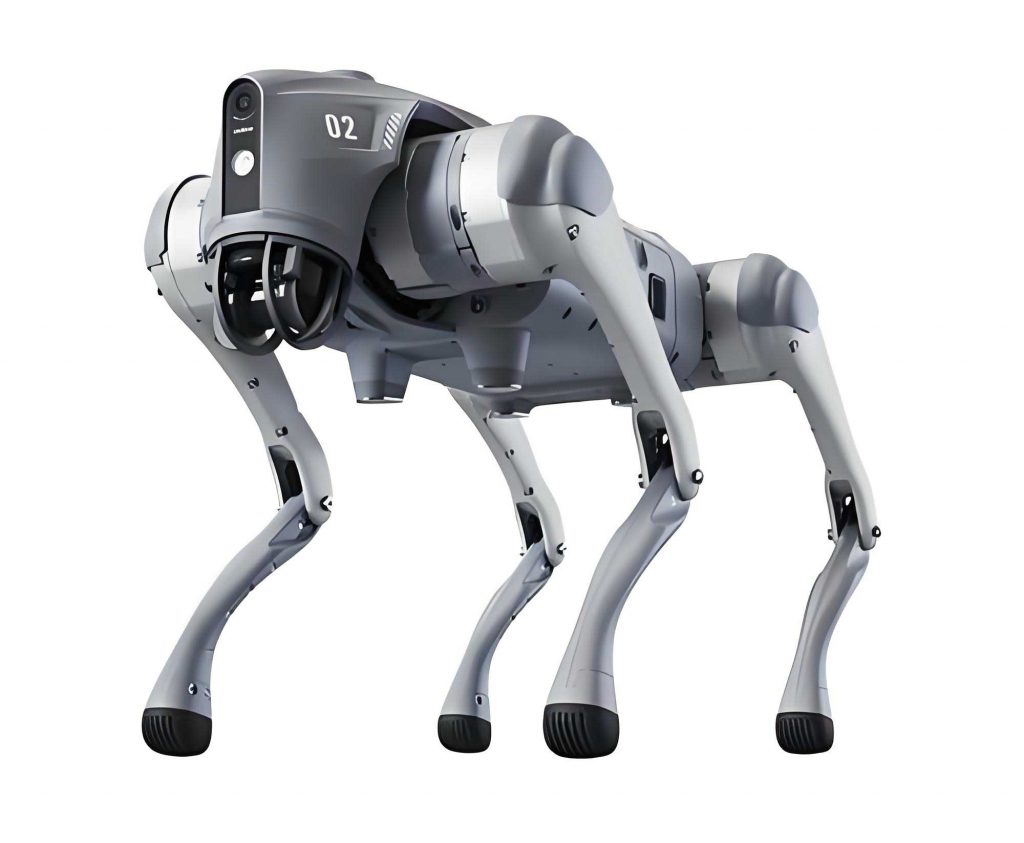
The core of our approach involves modeling the robot dog’s posture and gait using a simplified representation in a virtual space. The robot dog under consideration features eight degrees of freedom overall, with each leg having two degrees of freedom. This structure allows for flexible movement but requires precise control to achieve stable gaits. Our system utilizes a PC-based client and a server embedded in the robot dog, communicating via wireless networks to transmit motion commands. The virtual environment projects three-dimensional coordinates of the robot dog’s key points onto a two-dimensional plane, making it easier for users to manipulate the robot dog’s posture through mouse drag-and-drop actions. This projection is based on mathematical transformations that ensure accuracy and realism in the simulated motions.
To model the gait of the quadruped robot, we start with the kinematic analysis of a single leg. Each leg consists of two segments connected by joints, analogous to the thigh and shin in biological systems. The position of the foot tip, denoted as point A, is critical for determining the joint angles. Let the lengths of the segments be $a$ and $b$, both set to 75 units in our implementation. The angles $\alpha$ and $\beta$ control the servo motors for the joints, with $\alpha$ representing the angle between the segments and $\beta$ the angle of the base joint relative to the horizontal axis. The coordinates $(x, y)$ of point A can be expressed as:
$$x = a \cos \beta + b \cos (\beta – \alpha)$$
$$y = a \sin \beta + b \sin (\beta – \alpha)$$
Given the mechanical constraints, $\alpha$ and $\beta$ are bounded within specific ranges: $\alpha \in [30^\circ, 170^\circ]$ and $\beta \in [0^\circ, 180^\circ]$. The inverse kinematics, which compute the angles from the foot position, are derived as:
$$\alpha = 2 \arccos \left( \frac{x}{150 \cos(\arctan(x/y))} \right)$$
$$\beta = \frac{\alpha}{2} + \arctan \left( \frac{x}{y} \right)$$
This formulation allows us to control the robot dog’s leg positions accurately. However, in a virtual environment, we must extend this to the entire quadruped robot. We define a global coordinate system with an origin at a reference point $P$, and each leg is assigned an offset vector based on the robot dog’s dimensions. For instance, the offset vectors for the four legs—left front (leg 1), right front (leg 2), right rear (leg 3), and left rear (leg 4)—are given by:
| Leg | Offset Vector |
|---|---|
| 1 | $\begin{bmatrix} x \\ y \\ z \end{bmatrix}$ |
| 2 | $\begin{bmatrix} x \\ y – W \\ z \end{bmatrix}$ |
| 3 | $\begin{bmatrix} x + L \\ y – W \\ z \end{bmatrix}$ |
| 4 | $\begin{bmatrix} x + L \\ y \\ z \end{bmatrix}$ |
Here, $W$ and $L$ represent the width and length of the robot dog, respectively, and $(x, y, z)$ is the initial position. The coordinates of key points on each leg, such as the foot tip (A), knee joint (B), and hip joint (O), are transformed into this global coordinate system using vector additions. For example, the position of point A in leg 1 is $\vec{PA} = \vec{PM} + \vec{AA}$, where $\vec{PM}$ is the offset vector. This enables us to compute all joint positions in three-dimensional space.
Next, we project these 3D coordinates onto a 2D plane for display in the virtual environment. This projection mimics the view from a camera and is defined by a projection plane with the equation $A(x – x_0) + B(y – y_0) + C(z – z_0) = 1$, where $(x_0, y_0, z_0)$ is a point on the plane and $\vec{n} = (A, B, C)$ is the normal vector. For any point $Q(x_q, y_q, z_q)$ on the robot dog, we find its projection $N$ by solving the line equations parallel to $\vec{n}$:
$$x = x_q + A t$$
$$y = y_q + B t$$
$$z = z_q + C t$$
Substituting into the plane equation yields the parameter $t$, and thus the coordinates of $N$:
$$x_N = x_q + A \left[ \frac{1 + A(x_0 – x_q) + B(y_0 – y_q) + C(z_0 – z_q)}{A^2 + B^2 + C^2} \right]$$
$$y_N = y_q + B \left[ \frac{1 + A(x_0 – x_q) + B(y_0 – y_q) + C(z_0 – z_q)}{A^2 + B^2 + C^2} \right]$$
$$z_N = z_q + C \left[ \frac{1 + A(x_0 – x_q) + B(y_0 – y_q) + C(z_0 – z_q)}{A^2 + B^2 + C^2} \right]$$
To convert this to 2D screen coordinates, we define a local coordinate system on the projection plane using vectors $\vec{U}$ and $\vec{V}$. The 2D coordinates $(u, v)$ are computed based on the angle $\theta$ between the projection vector and the reference axis:
$$u = |\vec{UN}| \cos \theta$$
$$v = |\vec{UN}| \sin \theta$$
where $\theta$ is determined using cross products to ensure correct quadrant placement. Finally, we apply offsets $m$ and $n$ to align with the display window, resulting in screen coordinates $(U, V)$:
$$U = u – m$$
$$V = n – v$$
This projection allows users to visualize and interact with the robot dog in a 2D interface. The drag-and-drop functionality is implemented by detecting mouse events and updating the coordinates of the foot tips. For example, if the user drags point A, the new coordinates are calculated as $U_{\text{new}} = U + \Delta x$ and $V_{\text{new}} = V + \Delta y$, and the inverse kinematics are recomputed to update the joint angles. This real-time feedback ensures that the virtual model reflects the intended posture.
On the server side, the robot dog decodes the transmitted data, which is sent as character strings and converted to floating-point values. Specific commands, such as “RunAction”, trigger the execution of pre-defined motion sequences stored in a list. By iterating through these sequences, the robot dog performs the actions in real-time. This system is built using Python, with the Raspberry Pi 4B serving as the controller for the physical robot dog. The communication protocol ensures reliable data transfer over wireless networks, enabling remote control and monitoring.
To validate our approach, we conducted experiments with a prototype robot dog. The virtual environment was set up with an initial posture and a projection plane defined by $x + y + z = 500$. The simulation window had dimensions of 512 by 600 pixels. We tested various gaits and postures by dragging the legs in the virtual interface and observing the corresponding movements in the physical robot dog. The results demonstrated a high degree of correspondence between the simulated and actual motions, confirming the accuracy of the projection transformations and the effectiveness of the drag-and-drop programming method.
In terms of performance, we evaluated the system’s responsiveness and stability. The table below summarizes key parameters used in the experiments:
| Parameter | Value | Description |
|---|---|---|
| Segment lengths ($a$, $b$) | 75 units | Lengths of thigh and shin segments |
| Angle ranges ($\alpha$, $\beta$) | 30°–170°, 0°–180° | Servo motor constraints |
| Projection plane | $x + y + z = 500$ | Equation for 3D to 2D mapping |
| Window size | 512 × 600 pixels | Simulation display dimensions |
The experiments revealed that the robot dog could successfully perform actions like walking, turning, and balancing based on the drag-and-drop inputs. For instance, we designed a walking gait by sequentially positioning the legs in a cyclic pattern. The joint angles computed from the foot positions ensured stable support and smooth transitions. The projection transformations maintained consistency between the 3D model and 2D display, allowing users to intuitively design complex gaits without deep expertise in robotics.
Moreover, we incorporated constraints to enhance realism in the virtual environment. For example, when only two legs (e.g., front and rear) are in contact with the ground, the system checks for balance by comparing the Y-coordinates of the legs. Legs with higher Y-values are considered supporting, while others are lifted. This prevents unnatural postures and improves the reliability of the gait design. The mathematical foundation for these constraints is derived from the kinematics and dynamics of the quadruped robot, ensuring that the simulated motions are physically plausible.
In conclusion, our remote drag-and-drop programming system offers a user-friendly approach to gait modeling and transformation for quadruped robot dogs. By leveraging coordinate transformations and projection techniques, we bridge the gap between virtual design and physical execution. This method reduces the time and effort required for motion programming, making it accessible to a broader audience. Future work will focus on integrating machine learning for adaptive gait optimization and expanding the system to support more complex environments. The versatility of this approach underscores its potential for advancing the field of quadruped robotics, particularly in applications requiring rapid prototyping and intuitive control.
The success of this project highlights the importance of accurate kinematic modeling and efficient communication systems in robotics. As robot dogs become more prevalent, tools like this will play a crucial role in democratizing their programming and enhancing their capabilities. We believe that our contributions will inspire further innovations in the design and control of quadruped robots, paving the way for more intelligent and autonomous systems.