
As a critical component in modern industrial robotics and precision machinery, the rotary vector reducer is renowned for its compact structure, high torque capacity, large reduction ratio, and excellent torsional stiffness. The pursuit of higher positioning accuracy and repeatability in robotic applications has placed increasingly stringent demands on the transmission performance of these reducers. Among all performance indicators, angular transmission error stands out as the most vital parameter, directly influencing the end-effector’s positioning precision. For high-precision rotary vector reducer models, the angular transmission error is typically required to be less than 1 arcminute. Achieving such exceptional precision necessitates a deep understanding and meticulous control of numerous influencing factors. The two predominant sources of error are the intentional profile modification of the cycloidal gears, essential for assembly, lubrication, and load distribution, and the inevitable clearances within the supporting bearings. While previous research has often investigated these factors in isolation, the complex, nonlinear interaction between cycloidal gear modification and bearing clearance in a complete rotary vector reducer system remains a challenging and critical area for exploration. This article delves into the development of a high-fidelity virtual prototype for a rotary vector reducer, leveraging advanced multibody dynamics simulation techniques. The model uniquely integrates detailed gear contact mechanics, precise cycloidal tooth profile modifications, and realistic bearing clearances, providing a novel and powerful platform to study their combined and individual effects on the overall angular transmission error.
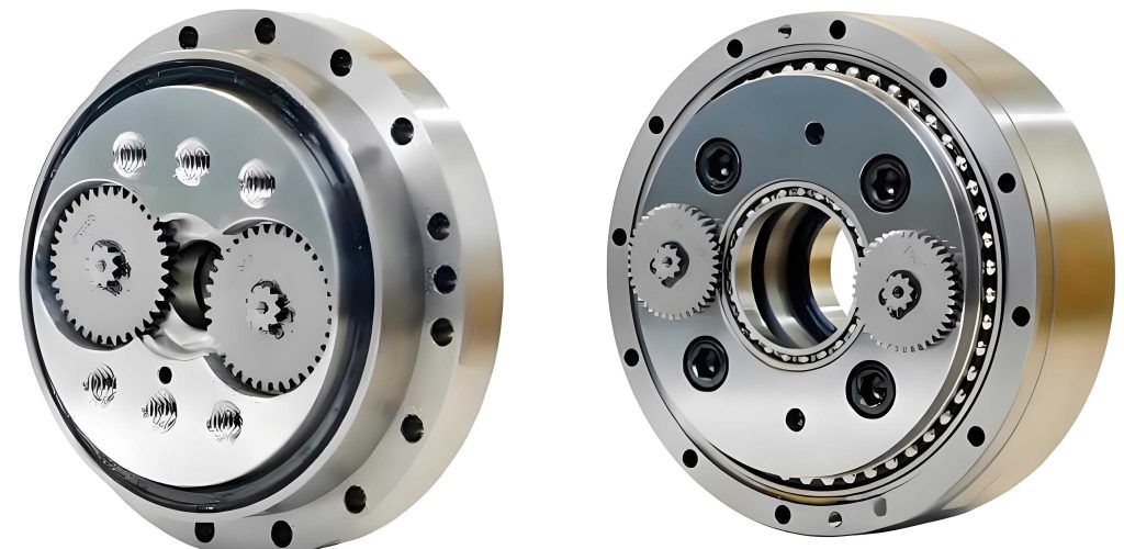
The rotary vector reducer employs a two-stage speed reduction mechanism. The first stage is a conventional involute planetary gear train, and the second stage is the unique cycloidal-pin gear (or “RV”) mechanism. This design inherently introduces multiple parallel load paths and statically indeterminate structures to enhance rigidity. For instance, the eccentric motion of the cycloidal disks is typically driven by three or more crankshafts arranged in parallel, forming a parallel double-crank mechanism. While beneficial for load sharing, this creates numerous redundant constraints, or “virtual constraints,” within the system from a purely kinematic perspective. Accurately modeling the dynamics of a rotary vector reducer requires resolving these constraints while simultaneously capturing the nonlinear contact forces between all mating gear teeth and the effects of internal clearances. My approach centers on building a multibody dynamics simulation model that addresses these complexities through a combination of the most advanced contact algorithms and a specialized method for modeling bearing joints.
Mathematical Foundation and Virtual Prototype Development
The cornerstone of an accurate dynamic model for a rotary vector reducer lies in the precise mathematical description of the gear contacts and joint constraints. The contact forces between all interacting components—the sun and planetary gears, the cycloidal disk and pins, and the pins and their housing—are governed by impact dynamics. The model employed here utilizes a modified Hertzian contact law, specifically the Lankarni-Nikravesh formulation, which is well-suited for the intermittent contacts that can occur due to clearances. The normal contact force \( f_n \) is calculated as:
$$ f_n = k \delta^{m_1} + D \dot{\delta} \delta^{m_1} $$
where \( k \) is the contact stiffness, \( \delta \) is the penetration depth between the contacting geometries, \( \dot{\delta} \) is the penetration velocity, \( D \) is a damping coefficient, and \( m_1 \) is a stiffness exponent (often 1.5 for metallic contact). This formulation is applied pairwise to define the force interactions across the entire gear mesh network of the rotary vector reducer.
To detect these contacts efficiently within the complex 3D geometry of a rotary vector reducer, a hybrid contact detection algorithm is implemented. This algorithm combines the efficiency of the Boundary Box (BBox) method for initial broad-phase search with the precision of the Relative Coordinate Configuration Space method for narrow-phase, accurate penetration calculation. This combination is essential for handling the large number of potential contact pairs (e.g., 40 pins against two cycloidal disks, each with 39 teeth) in a computationally feasible manner.
The most critical and innovative aspect of this rotary vector reducer model is the treatment of bearings and redundant constraints. Traditional kinematic joints (revolute, cylindrical) would over-constrain the parallel mechanisms in the RV stage. To eliminate these virtual constraints while introducing realistic bearing clearances, key bearings are replaced with nonlinear spring-damper force elements, which I refer to as “Spring Force Bearing Units.”
Consider a radial bearing connecting Body A and Body B. A local coordinate system is defined at the bearing’s nominal position. The spring force unit calculates the relative displacement vector \( \mathbf{r}_{AB} \) between the connection points on A and B projected into this local system. The radial clearance \( C_r \) is defined. The effective radial deformation \( \delta_r \) used to compute a restoring force is zero when the magnitude of the radial displacement \( |\mathbf{r}_{AB}| \) is less than \( C_r \). Once the displacement exceeds the clearance, the force activates:
$$ \delta_r = \begin{cases}
0 & \text{if } |\mathbf{r}_{AB}| \le C_r \\
|r_{AB}| – C_r & \text{if } |\mathbf{r}_{AB}| > C_r
\end{cases}
$$
$$ \mathbf{F}_{bearing} = – (k \delta_r + c \dot{\delta}_r) \cdot \frac{\mathbf{r}_{AB}}{|\mathbf{r}_{AB}|}
$$
where \( k \) is the radial stiffness and \( c \) is the damping coefficient. This method is applied to the main support bearings, the crankshaft support bearings, and the crankshaft-eccentric bearing (turn-arm bearing) in the rotary vector reducer model. It perfectly simulates the “free play” within the clearance zone and the stiff, damped response upon contact, without introducing any rotational constraint, thus solving the redundancy issue.
Modeling the Cycloidal Gear Profile and Modifications
The performance of a rotary vector reducer is extraordinarily sensitive to the tooth profile of its cycloidal disk. The theoretical, conjugate profile is generated by the rolling of a circle (the generating circle of the cycloid) inside or outside the pin circle. The standard profile ensures theoretically continuous line contact with zero backlash under ideal conditions. However, in a practical rotary vector reducer, modifications are mandatory. The primary types of modification for a rotary vector reducer cycloidal gear are:
- equidistance modification: Altering the radius of the generating circle or the pin circle.
- profile shift modification: Shifting the tool profile relative to the workpiece during generation.
- Combined modification: A superposition of both to optimize contact pattern and backlash.
For the specific rotary vector reducer model analyzed here (akin to an RV-80E-81), a combined negative modification was applied. The mathematical description of the modified tooth profile is foundational to the virtual prototype. Starting from the standard cycloidal profile equations, the modification parameters are introduced. Let \( R_p \) be the pin circle radius, \( r_p \) the pin radius, \( E \) the eccentricity, \( z_c \) the number of cycloidal disk lobes, and \( z_p \) the number of pins. The standard tooth profile coordinates (in a coordinate system fixed to the cycloidal disk) are given by:
$$ x = (R_p – \Delta R) \sin(\psi) – (r_p – \Delta r) \sin(\psi + \xi) – E \sin(z_p \psi) $$
$$ y = (R_p – \Delta R) \cos(\psi) – (r_p – \Delta r) \cos(\psi + \xi) – E \cos(z_p \psi) $$
where \( \psi \) is the generating angle, \( \xi = \arcsin( E \sin(z_p \psi) / (R_p – \Delta R) ) \), \( \Delta R \) represents the profile shift modification (negative for tooth thinning), and \( \Delta r \) represents the equidistance modification (negative for reducing the generating circle effect). In the modeled rotary vector reducer, values of \( \Delta R = -0.027 \text{ mm} \) and \( \Delta r = -0.022 \text{ mm} \) were used. This intentional thinning creates a small, controlled backlash between the cycloidal disk and the pins, which is essential for lubrication, thermal expansion accommodation, and assembly tolerance absorption. The geometric model of the rotary vector reducer components is built using these precise parametric equations, ensuring the virtual prototype accurately reflects the manufactured part.
| Modification Type | Mathematical Parameter | Primary Effect on Tooth Profile | Typical Purpose in a Rotary Vector Reducer |
|---|---|---|---|
| Negative Equidistance ( -Δr ) | Reduces effective generating circle radius. | Uniformly reduces tooth thickness along the profile. | Creates radial clearance for lubrication and assembly. |
| Negative Profile Shift ( -ΔR ) | Shifts base circle inward. | Thins the tooth, primarily near the tip and root. | Compensates for elastic deformation under load, improves load distribution. |
| Combined ( -Δr, -ΔR ) | Both parameters applied. | Creates a complex, optimized clearance distribution. | Balances backlash, stress, and lubrication requirements for the specific rotary vector reducer application. |
Incorporating Bearing Clearances and System Assembly Effects
Beyond gear modifications, the internal clearances of the supporting bearings constitute the second major source of angular error in a rotary vector reducer. These clearances are inherent to rolling element bearings and are categorized into internal radial clearance, internal axial clearance, and running clearance after mounting and thermal stabilization. For the high-precision bearings used in a rotary vector reducer, the internal radial clearance is the most critical for transmission error.
The modeling of these clearances was achieved using the Spring Force Bearing Units described earlier. The clearance values are not arbitrary but are selected based on bearing manufacturer recommendations (e.g., NSK, SKF) for precision applications. For the analysis of the rotary vector reducer model, three distinct clearance levels were defined for the main set of bearings: the main support bearings (between the output flange and the housing), the crankshaft support bearings, and the turn-arm bearings (between the crankshaft eccentric and the cycloidal disk bore).
| Scenario Name | Main Bearing Radial Clearance (µm) | Crankshaft Support Bearing Clearance (µm) | Turn-Arm Bearing Clearance (µm) | Description |
|---|---|---|---|---|
| Ideal/Reference | 0 | 0 | 0 | Perfectly rigid joints, establishes baseline model accuracy. |
| Precision Grade | 10 | 10 | 10 | Typical high-precision bearing clearance level for a rotary vector reducer. |
| Commercial/Relaxed Grade | 20 | 20 | 20 | Larger clearance, may be found in standard or high-volume production. |
Furthermore, the “as-built” condition of the rotary vector reducer includes dimensional tolerances on other components. To simulate a worst-case or realistic scenario for backlash in the cycloid-pin stage, the model incorporates these tolerances. The pin diameter, the pin hole diameter in the pin gear housing, and the pin circle diameter (the diameter on which the pin centers lie) are all assigned values at the limits of their tolerance bands that maximize the effective operational backlash. This creates a comprehensive virtual prototype of a rotary vector reducer that includes both intentional design modifications (cycloid profile) and unavoidable manufacturing variations (bearing clearances, part tolerances).
Simulation Results and Angular Transmission Error Analysis
With the complete multibody dynamics model of the rotary vector reducer constructed, simulations were performed under no-load conditions with a constant input speed. The primary output is the angular transmission error (ATE), defined as the difference between the theoretical output rotation angle and the actual simulated output rotation angle at any given time \( t \):
$$ \theta_{er}(t) = \frac{\theta_{in}(t)}{R} – \theta_{out}(t) $$
where \( R \) is the nominal reduction ratio of the rotary vector reducer (e.g., 81 for the model studied), \( \theta_{in}(t) \) is the input shaft rotation, and \( \theta_{out}(t) \) is the output flange rotation. The ATE is typically measured in arcminutes or arcseconds.
The initial validation of the rotary vector reducer virtual prototype was conducted using a configuration with standard, unmodified cycloidal profiles and zero bearing clearances. The simulated angular velocities of the sun gear, planet gears, and output carrier were compared against theoretical kinematic calculations. The results showed a near-perfect match, with relative errors less than 0.2%, confirming the fundamental kinematic correctness of the model. The simulated ATE for this ideal configuration was found to be approximately 0.043 arcminutes. This residual error can be considered the inherent numerical “noise” or baseline accuracy of the simulation model itself, which is remarkably low and validates the model’s fidelity.
Next, the model was configured with the negatively modified cycloidal profile and the maximized pin gear backlash from dimensional tolerances, but still with zero bearing clearances. The simulation result was a marked increase in ATE to 0.196 arcminutes. This demonstrates the model’s high sensitivity to geometric changes in the gear teeth and confirms that the chosen modification scheme for this specific rotary vector reducer introduces a measurable, though still within specification, amount of kinematic error under no-load conditions.
The most significant insights came from introducing the bearing clearances. The following table and analysis summarize the key findings from simulating the three bearing clearance scenarios on the modified rotary vector reducer model.
| Cycloid Profile | Bearing Clearance Scenario | Peak-to-Peak Angular Transmission Error (Arcminutes) | Key Observation |
|---|---|---|---|
| Standard (Ideal) | Ideal (0 µm) | 0.043 | Baseline model numerical accuracy. |
| Modified (Realistic) | Ideal (0 µm) | 0.196 | Impact of cycloid modification and gear backlash alone. |
| Modified (Realistic) | Precision Grade (10 µm) | 0.760 | Clearance dramatically amplifies error; still near 1′ limit. |
| Modified (Realistic) | Commercial Grade (20 µm) | 1.362 | Error exceeds common high-precision spec (>1′), highlighting criticality of bearing selection. |
The results are unequivocal: bearing clearance is a dominant factor influencing the angular transmission error of a rotary vector reducer. The increase in ATE is not linear but significant. With precision-grade clearances (10 µm), the ATE increased nearly fourfold compared to the zero-clearance modified case. With commercial-grade clearances (20 µm), the ATE exceeded the 1 arcminute threshold commonly associated with high-precision rotary vector reducer units. The dynamics revealed that these clearances allow small, quasi-random relative motions between the crankshafts, cycloidal disks, and housing. These motions are intermittently arrested by contact within the bearings, generating impacts and transient vibrations that manifest as output angle jitter, thereby increasing the peak-to-peak ATE.
Additionally, the model successfully replicated the known multi-tooth contact behavior of the cycloidal stage. Under load, the force distribution across the pins was observed, showing that nearly half of the pins (a characteristic of the cycloidal design) share the load simultaneously, albeit with varying force magnitudes due to the modifications and clearances.
Extended Discussion: Loaded Conditions and Error Spectra
While the core analysis focused on no-load conditions to isolate kinematic and clearance effects, the developed virtual prototype for the rotary vector reducer is fully capable of simulating loaded operations. Applying an output torque load introduces elastic deformations in the teeth, shafts, and bearings, which will further influence the angular transmission error. The ATE under load typically consists of two main components: a periodic component synchronous with the gear mesh frequencies (both involute and cycloidal), and a non-periodic or stochastic component largely driven by clearance-induced impacts.
The Fourier transform of the ATE time-history signal is an invaluable tool. For a rotary vector reducer, one would expect prominent spectral peaks at the following frequencies and their harmonics:
- The cycloidal mesh frequency: \( f_{cyclo} = f_{in} \times z_{planet} \times (z_p / |z_p – z_c|) \), where \( f_{in} \) is input shaft frequency, \( z_{planet} \) is planet gear teeth, \( z_p \) is pin number, \( z_c \) is cycloid lobe number. This is usually the highest frequency component.
- The involute planetary mesh frequency: \( f_{inv} = f_{in} \times z_{sun} \).
- The planet pass frequency: \( f_{pass} = f_{in} \times N_{planets} \).
Simulations with the rotary vector reducer model show that increased bearing clearance not only raises the amplitude of the ATE but also broadens the spectral peaks and raises the noise floor across the frequency spectrum, indicating increased nonlinear, chaotic behavior due to impacting within the joints.
Conclusions and Implications for Rotary Vector Reducer Design
This comprehensive study has successfully established and validated a high-fidelity virtual prototyping methodology for analyzing the angular transmission error of a rotary vector reducer. The integration of advanced multibody contact algorithms with a novel spring-force-based bearing clearance modeling technique has proven to be a powerful and necessary approach. The model transcends the limitations of purely kinematic or isolated factor analyses by simultaneously incorporating cycloidal gear profile modifications, manufacturing tolerances, and realistic bearing clearances into a single dynamic system.
The key findings for this specific rotary vector reducer configuration are:
- The chosen negative equidistance and profile shift modifications for the cycloidal gear introduce a foundational, but acceptable, level of kinematic error (~0.2 arcminutes).
- Bearing internal radial clearance is a critical design parameter. For the studied rotary vector reducer, increasing the clearance from a precision grade (10 µm) to a more commercial grade (20 µm) caused the predicted no-load ATE to surpass the 1 arcminute performance benchmark.
- The interaction between gear backlash and bearing clearance is complex and nonlinear. Clearances amplify the kinematic error from modifications by enabling small, impactful relative motions within the drive train.
The developed virtual prototype of the rotary vector reducer serves as a potent digital twin. It provides a new modeling paradigm that enables designers to perform virtual sensitivity analyses, answering crucial questions: How much cycloid modification is optimal when combined with a specific bearing precision class? What is the tolerance stack-up limit before ATE degrades unacceptably? By enabling such explorations digitally, this approach can significantly reduce the cost and time associated with physical prototyping and testing of high-precision rotary vector reducer systems, guiding designers toward more robust and accurate designs.
Future work will involve coupling this multibody dynamics model with finite element analysis to capture component flexibility under high load, and integrating thermal models to predict the effects of running clearance changes due to operational heating on the long-term angular transmission error stability of the rotary vector reducer.