
Throughout my graduate research, I focused on enhancing the safety and intelligence of a humanoid robot system that operates without dedicated joint torque sensors or wrist force sensors. The central problem was how to provide the robot with a reliable force perception capability while keeping the hardware simple, low-cost, and mechanically stiff. In this article, I present a comprehensive solution that integrates system design, dynamic modeling, neural-network-based error compensation, sensorless external force detection, and impedance control for physical human-robot interaction. The proposed methods were verified on a real semi-humanoid robot platform with a wheeled mobile base and two seven-degree-of-freedom anthropomorphic arms. The experimental results demonstrate that the sensorless force detection method achieves high accuracy and real-time performance, and the safety interaction strategies effectively protect both humans and the robot.
Introduction and Motivation
The rapid development of artificial intelligence and robotics has shifted the expectation of robots from repetitive industrial manipulators to intelligent service platforms that can work in human-centered environments. A humanoid robot is particularly appealing because of its anthropomorphic appearance and natural motion compatibility. However, the deployment of humanoid robots in daily life requires strict safety guarantees. One of the most critical capabilities is the detection of external forces, which enables collision detection, compliant motion, direct teaching, and cooperative manipulation. Traditional methods rely on six-axis force/torque sensors at the wrist or torque sensors embedded in joints. These sensors are expensive, complicate the mechanical design, reduce system stiffness, and limit the operational load. For a humanoid robot intended for broad research and service use, a sensorless approach is highly desirable.
In this research, I proposed a sensorless external force detection method based on joint motor current sensing, dynamic model calculation, and neural network compensation. The key idea is to compare the actual joint torque, reconstructed from the motor current, with the theoretical joint torque computed from the inverse dynamics model. The difference between these two values represents the external torque applied to the robot joint, provided that the model is accurate. However, the dynamics model inevitably suffers from nonlinear factors such as friction, joint backlash, and flexibility. To compensate for these modeling errors, I employed a back-propagation neural network that learns the residual error from experimental data. The compensated external torque can be used both for collision response and for impedance-based compliant control. This approach significantly improves the force detection accuracy compared with traditional friction-model-based compensation methods while maintaining real-time performance.
Physical Humanoid Robot System Design
The humanoid robot system developed in this research adopts a semi-humanoid configuration. The upper body is anthropomorphic, including a head, a waist, two seven-degree-of-freedom arms, and four-finger dexterous hands. The lower body is a wheeled omnidirectional mobile platform equipped with a laser rangefinder, odometry, and ultrasonic sensors. This configuration balances human-like appearance with the practical requirements of indoor navigation and manipulation. The overall height of the robot is 160 cm, and the shoulder width is 50 cm, which resembles the proportions of an adult human.
Each anthropomorphic arm uses an unbiased non-spherical wrist configuration to mimic the human arm’s motion range. The arm has three intersecting joints at the shoulder, one revolute joint at the elbow, and three intersecting joints at the wrist. The upper arm and forearm lengths are both 25 cm. For each joint, a brushless DC motor drives a harmonic reducer. The reduction ratios and motor parameters are summarized in the following table.
| Joint | Power (W) | Torque constant (mNm/A) | Damping (mNm/rpm) | Peak current (A) | No-load speed (rpm) | Reduction ratio | Efficiency |
|---|---|---|---|---|---|---|---|
| 1 | 100 | 53.4 | 0.00561 | 4.43 | 3840 | 80 | 0.95 |
| 2 | 100 | 53.4 | 0.00561 | 4.43 | 3840 | 80 | 0.95 |
| 3 | 70 | 46.1 | 0.00210 | 2.73 | 6450 | 80 | 0.95 |
| 4 | 70 | 46.1 | 0.00210 | 2.73 | 6450 | 80 | 0.95 |
| 5 | 50 | 46.1 | 0.00210 | 1.61 | 6080 | 80 | 0.95 |
| 6 | 20 | 30.8 | 0.00210 | 1.50 | 9690 | 159 | 0.93 |
| 7 | 20 | 30.8 | 0.00210 | 1.50 | 9690 | 159 | 0.93 |
The control architecture is a hierarchical system. The top layer is a task manager implemented on an NVIDIA TX2 embedded platform, which handles environment perception, high-level decision making, and communication. The middle layer contains an upper-body motion planner and a base motion planner. The lower layer consists of joint servo controllers and base motor controllers. The joint servo controllers were custom-designed for this humanoid robot. They integrate a three-phase H-bridge, current sensing amplifiers, encoder interfaces, and CAN communication. The custom driver board is 80 mm × 65 mm × 12 mm, which fits compactly inside the robot arm. The current sensing circuit uses a differential amplifier to measure the voltage across a sampling resistor in series with the motor phase. This design ensures high-accuracy current acquisition, which is essential for sensorless torque estimation.
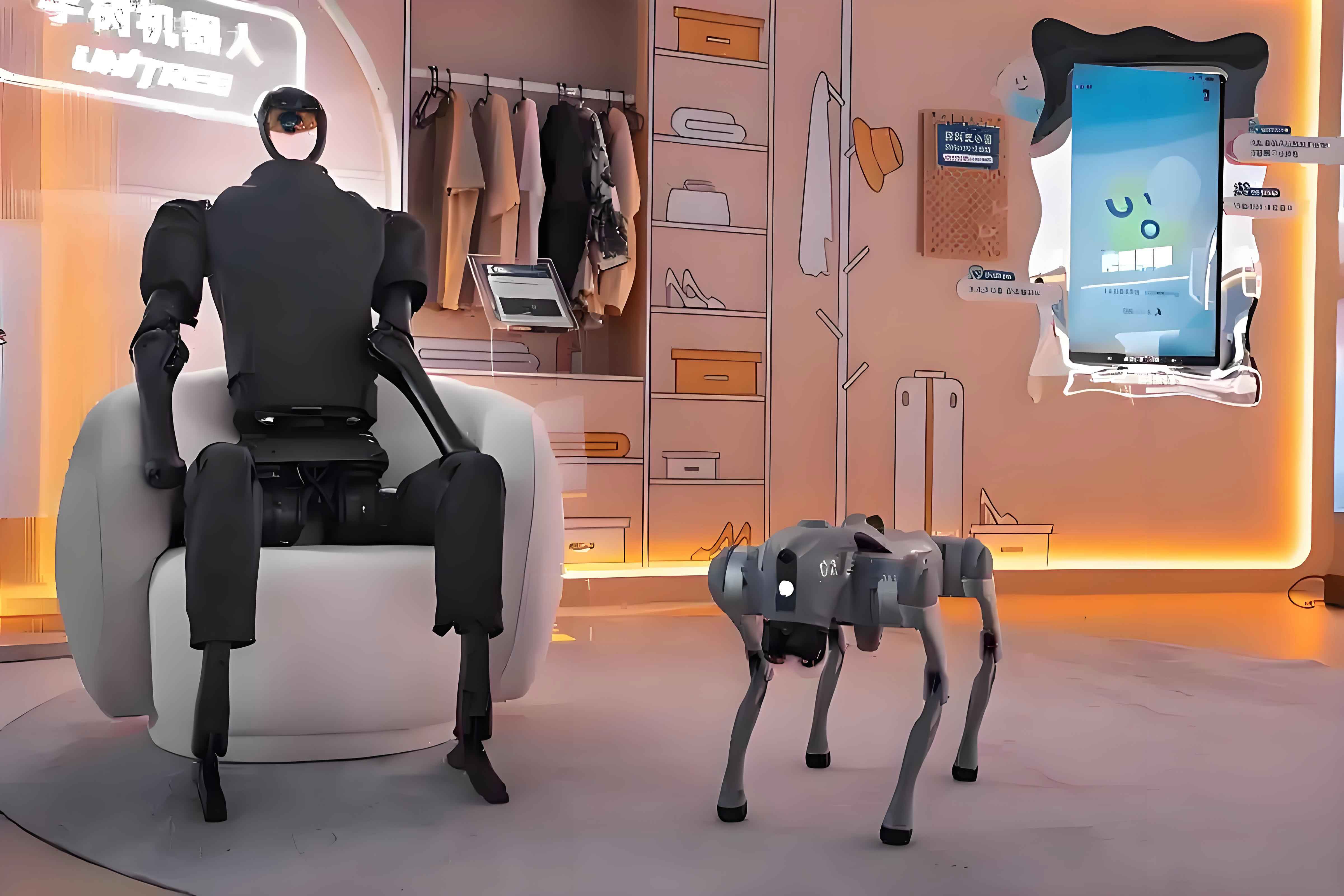
The robot is equipped with more than one hundred sensors, including nine-axis inertial measurement units, stereo cameras, microphones, a laser radar, ultrasonic transducers, wheel odometers, and torque measurement units based on the current sensing mentioned above. These sensors enable autonomous navigation, simultaneous localization and mapping (SLAM), object detection, face recognition, voice interaction, and remote teleoperation. In the autonomous control mode, the humanoid robot can receive voice commands, navigate to a target object, grasp it, and return to the user. In the teleoperation mode, an inertial motion-capture suit worn by the operator captures human joint angles and maps them directly to the robot arm joints, which is possible because the robot’s arm configuration closely matches a human arm.
Kinematic and Dynamic Modeling of the Humanoid Robot Arm
For the control and force estimation, I established both kinematic and dynamic models of the seven-degree-of-freedom anthropomorphic arm. The Denavit–Hartenberg (DH) convention was used to build the kinematic model. The DH frames are attached to each link according to standard rules. The following table lists the DH parameters for the right arm.
| Link \(i\) | \(a_{i-1}\) (m) | \(\alpha_{i-1}\) (°) | \(d_i\) (m) | \(\theta_i\) (°) |
|---|---|---|---|---|
| 1 | 0 | 0 | 0.225 | -90 |
| 2 | 0 | -90 | 0 | -90 |
| 3 | 0 | 90 | 0.25 | 90 |
| 4 | 0 | 90 | 0 | 0 |
| 5 | 0 | -90 | 0.25 | 90 |
| 6 | 0 | 90 | 0 | 90 |
| 7 | 0 | 90 | 0 | -90 |
The homogeneous transformation matrix between consecutive link frames is given by
$$
T_i^{i-1} =
\begin{bmatrix}
\cos\theta_i & -\sin\theta_i & 0 & a_{i-1}\\[2pt]
\sin\theta_i\cos\alpha_{i-1} & \cos\theta_i\cos\alpha_{i-1} & -\sin\alpha_{i-1} & -d_i\sin\alpha_{i-1}\\[2pt]
\sin\theta_i\sin\alpha_{i-1} & \cos\theta_i\sin\alpha_{i-1} & \cos\alpha_{i-1} & d_i\cos\alpha_{i-1}\\[2pt]
0 & 0 & 0 & 1
\end{bmatrix}.
$$
Multiplying all seven transformation matrices yields the forward kinematics \(T_7^0\), which relates the joint angles to the end-effector pose. The workspace of the designed arm covers a large portion of a sphere centered at the shoulder, enabling natural human-like reaching motions.
For dynamics, I used the Lagrangian formulation. The kinetic energy of the robot is the sum of link kinetic energies and actuator rotor kinetic energies. The total potential energy depends on the link masses and centers of mass. The resulting dynamic equation is expressed as
$$
\boldsymbol{\tau} = \mathbf{M}(\mathbf{q})\ddot{\mathbf{q}} + \mathbf{C}(\mathbf{q},\dot{\mathbf{q}})\dot{\mathbf{q}} + \mathbf{G}(\mathbf{q}),
$$
where \(\mathbf{M}(\mathbf{q})\) is the symmetric inertia matrix, \(\mathbf{C}(\mathbf{q},\dot{\mathbf{q}})\) contains Coriolis and centrifugal terms, and \(\mathbf{G}(\mathbf{q})\) is the gravity vector. The dynamic parameters, including masses, center-of-mass locations, and inertia tensors, were obtained from the CAD model of the humanoid robot. The table below lists these parameters for the first two links of the arm.
| Link | Mass (kg) | COM (mm) | Inertia tensor \(I\) (kg·m²) |
|---|---|---|---|
| 1 | 1.092 | (0.12, 120.15, 0.05) | \(\begin{bmatrix} 0.025 & 0 & 0 \\ 0 & 0.017 & 0 \\ 0 & 0 & 0.025 \end{bmatrix}\) |
| 2 | 0.534 | (22.53, 127.76, -0.01) | \(\begin{bmatrix} 0.024 & 0 & 0 \\ 0 & 0.016 & 0 \\ 0 & 0 & 0.024 \end{bmatrix}\) |
For the sensorless force detection algorithm, I simplified the seven-degree-of-freedom arm to a two-degree-of-freedom planar system by locking joints 2, 3, 5, 6, and 7. The simplified model consists of a shoulder joint \(q_1\) and an elbow joint \(q_2\), with link lengths \(l_1\) and \(l_2\), and concentrated masses \(m_1\) and \(m_2\). The dynamic equations for this two-link model are
$$
\begin{aligned}
\tau_1 &= (m_1+m_2)l_1^2 \ddot{q}_1 + m_2 l_2^2 (\ddot{q}_1+\ddot{q}_2) \\
&\quad + m_2 l_1 l_2 \cos q_2 (2\ddot{q}_1+\ddot{q}_2) – m_2 l_1 l_2 \sin q_2 (\dot{q}_2^2+2\dot{q}_1\dot{q}_2) \\
&\quad + (m_1+m_2) g l_1 \cos q_1 + m_2 g l_2 \cos(q_1+q_2),
\end{aligned}
$$
$$
\begin{aligned}
\tau_2 &= m_2 l_2^2 (\ddot{q}_1+\ddot{q}_2) + m_2 l_1 l_2 \cos q_2 \ddot{q}_1 + m_2 l_1 l_2 \sin q_2 \dot{q}_1^2 \\
&\quad + m_2 g l_2 \cos(q_1+q_2).
\end{aligned}
$$
This simplified model was used for the simulation of impedance control and for the generation of training data of the neural network compensator. Although the full seven-degree-of-freedom model is more accurate, the two-link model captures the essential dynamics for proving the effectiveness of the proposed compensation approach.
Sensorless External Force Detection Based on Motor Current
The fundamental idea of sensorless force detection is to estimate the actual joint torque from the motor current and compare it with the theoretical torque from the dynamic model. The residual is the external torque. The motor torque is proportional to the armature current in a permanent-magnet DC motor:
$$
T_e = C_{tm} i_s,
$$
where \(C_{tm}\) is the motor torque constant and \(i_s\) is the armature current. The motor dynamic equation is
$$
T_e – T_L – B_m \omega = J \frac{d\omega}{dt},
$$
where \(T_L\) is the load torque, \(B_m\) is the damping coefficient, \(J\) is the rotor inertia, and \(\omega\) is the motor angular speed. After the harmonic reducer, the joint torque is
$$
\tau_{\text{em}} = \eta i \, T_L,
$$
where \(i\) is the reduction ratio and \(\eta\) is the transmission efficiency. Combining these equations, the actual joint torque can be expressed as
$$
\tau_{\text{em}} = \eta i C_{tm} i_s – \eta i^2 B_m \dot{q} – \eta i^2 J \ddot{q},
$$
where \(q\), \(\dot{q}\), and \(\ddot{q}\) are the joint angle, velocity, and acceleration. Hence, the external torque at the joint is
$$
\tau_{\text{ext}} = \tau_{\text{em}} – \tau_{\text{md}},
$$
where \(\tau_{\text{md}}\) is the theoretical torque computed from the inverse dynamics model \(\tau_{\text{md}}=\mathbf{M}\ddot{q}+\mathbf{C}\dot{q}+\mathbf{G}\). Under ideal conditions when no external force exists, \(\tau_{\text{ext}}\) should be zero. In practice, however, due to friction, backlash, and other unmodeled effects, there is a significant residual error. The following figure shows the model error when the humanoid robot arm moved from 0° to 90° without any external disturbance.
In the figure, the green line is the joint speed, the red line is the joint acceleration, the blue line is the joint angle, the black line is the actual joint torque \(\tau_{\text{em}}\), and the magenta line is the theoretical torque \(\tau_{\text{md}}\). It is evident that large deviations occur especially during the acceleration and deceleration phases. These deviations come from nonlinear friction, harmonic drive effects, and motor driver quantization, all of which are difficult to model analytically.
Neural Network Compensation of Model Errors
To improve the accuracy of the sensorless external force detection, I introduced a back-propagation neural network to learn and compensate the model error. The network takes the joint state as input and outputs the predicted model error. The input vector is
$$
\mathbf{x} = [q_1,\ q_2,\ \dot{q}_1,\ \dot{q}_2,\ \ddot{q}_1,\ \ddot{q}_2]^T,
$$
and the target output is the model error
$$
\mathbf{y} = [\tau_{\text{em},1}-\tau_{\text{md},1},\ \tau_{\text{em},2}-\tau_{\text{md},2}]^T.
$$
The network has one hidden layer with 500 neurons and uses the mean squared error (MSE) as the loss function. Training data were collected by exciting the robot arm across the entire joint space. Data sets included single-joint motions and coordinated two-joint motions, both in positive and negative directions. In total, 56 datasets were collected. A subset of 40 datasets was used for training, and the remaining 16 datasets were used for testing. Several network architectures were evaluated; the following table summarizes the training and test MSE for a selection of configurations.
| Hidden layer 1 | Hidden layer 2 | Training MSE | Test MSE |
|---|---|---|---|
| 6 | 0 | 0.0340 | 0.0347 |
| 50 | 0 | 0.0086 | 0.0103 |
| 100 | 0 | 0.0079 | 0.0108 |
| 200 | 0 | 0.0059 | 0.0077 |
| 500 | 0 | 0.0013 | 0.0013 |
| 100 | 20 | 0.0246 | 0.0245 |
| 100 | 50 | 0.0261 | 0.0254 |
| 300 | 40 | 0.0013 | 0.0023 |
| 80 | 80 | 0.0039 | 0.0043 |
It was found that a single hidden layer with 500 neurons yielded the best generalization performance. The final compensation model is represented as
$$
\boldsymbol{\tau}_{nn} = \mathcal{N}(\mathbf{q}, \dot{\mathbf{q}}, \ddot{\mathbf{q}}).
$$
The compensated external torque is then
$$
\boldsymbol{\tau}_{\text{ext}} = \boldsymbol{\tau}_{\text{em}} – \boldsymbol{\tau}_{\text{md}} – \boldsymbol{\tau}_{nn}.
$$
At run time, the joint controller samples the motor current, position, and velocity at a high rate. The acceleration is obtained by numerical differentiation and low-pass filtering. The trained neural network is evaluated on the TX2 processor within the control loop. This process preserves real-time performance because the network has only one hidden layer and the input dimension is six.
Experimental Validation of Force Detection Accuracy
I performed a series of experiments to validate the proposed sensorless detection method on the humanoid robot. A high-precision force gauge was used to apply known forces to different points on the arm. The robot was placed in four distinct configurations to decouple the effects of the two joints. For joint 1, the arm was held such that the upper arm and forearm were perpendicular, and forces were applied along the forearm direction. For joint 2, forces were applied perpendicular to the forearm. The peak values of the measured force and the detected forces were compared. The following table shows the results for the two compensation methods: the Stribeck friction model compensation and the proposed neural network compensation.
| Motion | \(\tau_{\text{SB}}\) (N) | \(\tau_{\text{NN}}\) (N) | Force gauge (N) | ERR-SB (N) | ERR-NN (N) |
|---|---|---|---|---|---|
| Action 1-1 | 23.19 | 22.19 | 21.94 | 1.25 | 0.25 |
| Action 1-2 | 41.75 | 42.76 | 42.74 | -0.99 | 0.02 |
| Action 2-1 | 33.29 | 34.35 | 34.14 | -0.85 | 0.21 |
| Action 2-2 | 40.05 | 39.66 | 39.81 | 0.24 | -0.15 |
| Action 3-1 | 37.98 | 37.15 | 36.94 | 1.04 | 0.21 |
| Action 3-2 | 26.66 | 26.24 | 26.12 | 0.54 | 0.12 |
| Action 4-1 | 30.23 | 30.34 | 30.48 | -0.25 | -0.14 |
| Action 4-2 | 27.85 | 28.45 | 28.20 | -0.35 | 0.25 |
The average absolute error of the neural network method was below 0.3 N, while the Stribeck friction model method produced errors often exceeding 1 N. The improvement is significant, demonstrating that the neural network effectively captures complex nonlinear effects such as position-dependent friction and harmonic drive losses. The remaining small errors are mainly due to current measurement noise and minor variations in the force application angle.
In addition to static accuracy, I conducted tapping experiments to verify the real-time response. The robot was held in a fixed pose, and an experimenter tapped the end-effector with different objects: a hand, a ruler, a book, and a sheet of paper. The detected torque signals for joints 1 and 2 were recorded. The results showed that for sufficiently strong impacts, both joints detected the collision clearly. For the very light touch of paper, joint 2 could not detect a clear peak, while joint 1 recorded a small torque of about 0.12 Nm. This indicates that the detection threshold of the current system lies around 0.2 Nm. The humanoid robot is therefore able to detect collisions that could cause harm to humans or the robot itself, while ignoring tiny perturbations that are not safety-relevant.
Impedance Control for Safe Physical Human-Robot Interaction
With the sensorless external torque available in joint space, I implemented impedance control to achieve compliant behavior during physical human-robot interaction. Impedance control shapes the dynamic relationship between the external force and the robot motion. The target impedance model in joint space is described by
$$
\mathbf{M}_d (\ddot{\mathbf{q}}_c – \ddot{\mathbf{q}}_r) + \mathbf{B}_d (\dot{\mathbf{q}}_c – \dot{\mathbf{q}}_r) + \mathbf{K}_d (\mathbf{q}_c – \mathbf{q}_r) = \boldsymbol{\tau}_{\text{ext}},
$$
where \(\mathbf{q}_c\) is the commanded joint angle, \(\mathbf{q}_r\) is the reference joint angle, and \(\mathbf{M}_d\), \(\mathbf{B}_d\), \(\mathbf{K}_d\) are the desired inertia, damping, and stiffness matrices. In practice, these matrices are chosen as diagonal, so that each joint can be treated independently. The impedance control loop generates a joint position correction from the external torque:
$$
\mathbf{q}_c = \mathbf{q}_r + \frac{\boldsymbol{\tau}_{\text{ext}}}{\mathbf{K}_d}
$$
in the static case, or more generally through the second-order dynamics above. Since the sensorless detection method already provides joint-space torques, no Jacobian transformation is needed. This simplifies the implementation and reduces the computation time.
I first performed simulations to study the influence of the impedance parameters on the system response. The target system was modeled as a second-order system
$$
G(s) = \frac{1}{M s^2 + B s + K}.
$$
By selecting different values of \(M\), \(B\), and \(K\), I observed changes in overshoot, settling time, and stability. The following tables summarize the simulation results.
| \(M\) (kg) | Steady-state error (m) | Settling time (s) | Overshoot (%) |
|---|---|---|---|
| 0.5 | 0 | 0.85 | 7 |
| 1 | 0 | 1.63 | 0 |
| 3 | 0 | 4.51 | 0 |
| \(B\) (N·s/m) | Steady-state error (m) | Settling time (s) | Overshoot (%) |
|---|---|---|---|
| 5 | 0 | 0.81 | 19 |
| 10 | 0 | 1.63 | 0 |
| 20 | 0 | 1.86 | 0 |
| \(K\) (N/m) | Steady-state error (m) | Settling time (s) | Overshoot (%) |
|---|---|---|---|
| 10 | 0 | 0.69 | 4.3 |
| 20 | 0 | 1.63 | 0 |
| 30 | 0 | 3.30 | 0 |
Based on these simulations, I selected \(\mathbf{M}_d = 1\) (diagonal), \(\mathbf{B}_d = 20\) (diagonal), and \(\mathbf{K}_d = 20\) (diagonal) in appropriate units to operate the robot in a critically damped or slightly overdamped condition, avoiding excessive overshoot while maintaining a reasonable response speed.
Safety Strategy: Collision Response and Compliant Control
In a real human-robot coexisting environment, the humanoid robot must distinguish between unexpected collisions and intentional physical interactions. Unexpected collisions require an immediate escape motion, while intentional interactions require the robot to be compliant. I integrated the stereo vision system into the safety strategy. The vision system continuously detects whether a human is present in the robot’s workspace. If no human is detected, the robot operates in the position control mode with the collision detection and response strategy. Once the external torque exceeds a threshold \(f_{\text{low}}^i\) for any joint, the robot switches to the reflex response strategy. The reflex control law is
$$
\boldsymbol{\tau} = \mathbf{G}(\mathbf{q}) – K_r \, \text{sign}(\boldsymbol{\tau}_{\text{ext}}),
$$
where \(K_r\) is a large positive gain. This drives the robot to move away from the collision source. In the experiments, the threshold was set to 0.5 Nm for joint 1. When the robot’s descending arm hit a wooden rod, the detection algorithm triggered the reflex motion almost immediately. Without the response, the maximum impact torque reached about 8 Nm and the rod broke. With the response, the maximum torque was limited to approximately 1.2 Nm and the rod remained intact. This demonstrated the effectiveness and real-time performance of the collision response strategy.
When a human is detected in the field of view, the robot switches from position control to impedance control. The sensorless external torque is fed into the impedance controller, which produces a joint position correction. The robot then follows the operator’s motion intention, enabling direct teaching or cooperative manipulation. This strategy prevents the robot from running away from a person who intends to interact, while still protecting against accidental impacts.
I conducted a direct teaching experiment on the humanoid robot. The robot started with both joints at 0°. An operator grasped the forearm and moved it through a desired trajectory. The sensorless detection algorithm measured the interaction torques. The impedance controller converted these torques into position corrections, and the robot tracked the operator’s motion smoothly. The recorded data showed that the maximum interaction torque remained below 5 Nm during the entire procedure, which indicates a low physical burden for the operator. The robot’s motion followed the applied force with no noticeable delay, and the position error converged to zero when the external force was removed.
Conclusion
In this research, I developed a complete sensorless external force detection method and applied it to a humanoid robot for safe physical human-robot interaction. The key contributions are the design of a low-cost, high-stiffness humanoid robot system with custom-built joint servo drivers; the establishment of kinematic and dynamic models for a seven-degree-of-freedom anthropomorphic arm; the proposal of a neural-network-compensated sensorless external force detection algorithm based on motor current; and the implementation of a vision-assisted safety strategy that switches between collision response and impedance control. The experimental results on the real humanoid robot platform verified that the detection accuracy is significantly improved over traditional friction-model-based methods, and the interaction strategy successfully enables direct teaching while maintaining safety. The proposed methods are cost-effective and can be transferred to other humanoid robot platforms that lack dedicated force sensors. Future work will extend the sensorless detection to full six-dimensional external force estimation in Cartesian space and integrate the method with advanced compliance control strategies for more complex human-robot collaboration tasks.