
In the field of industrial robotics, precision and efficiency are paramount, and the rotary vector reducer plays a critical role in achieving high-performance motion control. As a key component, the cycloidal gear within the rotary vector reducer directly influences transmission accuracy, durability, and overall system reliability. In this article, I delve into a theoretical study on the modification of cycloidal gears used in rotary vector reducers, focusing on a novel parabolic modification method. This approach aims to enhance meshing quality by minimizing transmission errors and ensuring optimal lubrication, thereby improving the functionality of rotary vector reducers in robotic applications. Through detailed mathematical derivations, comparative analyses, and transmission error assessments, I explore the advantages of this method over traditional techniques, providing insights that could redefine design paradigms for rotary vector reducers.
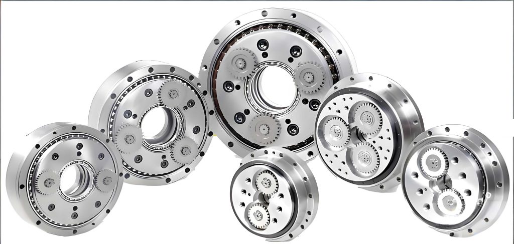
The rotary vector reducer, often abbreviated as RV reducer, is a sophisticated transmission device that combines a first-stage involute planetary gear system with a second-stage cycloidal-pinwheel planetary gear system. This composite structure enables high reduction ratios, compact design, and excellent torque capacity, making it ideal for robotic joints. However, the cycloidal gear, located at the low-speed end and directly connected to the output mechanism, is pivotal for determining the transmission accuracy of the rotary vector reducer. In theory, cycloidal-pinwheel transmissions engage in zero-backlash meshing, with nearly half of the pinwheel teeth participating simultaneously. In practice, manufacturing and assembly errors lead to deviations from the ideal tooth profile, causing interference, poor lubrication, and even jamming. Therefore, modifying the cycloidal gear tooth profile is essential to compensate for these errors, ensure smooth operation, and extend the lifespan of rotary vector reducers.
Traditionally, modification methods for cycloidal gears include isometric, shift-distance, and rotational-angle modifications, or a combination thereof, such as isometric-plus-shift-distance composite modification. These methods result in single-tooth contact under no-load conditions, with increased contact teeth under load due to deformation. However, in the main working region of the tooth profile, the modification amount tends to be excessive, leading to larger deviations from the fully conjugate tooth shape and increased transmission errors. This limitation motivates the exploration of alternative approaches. In this study, I propose a parabolic modification method based on the concept of single-tooth no-backlash mismatch modification. By superimposing a second-order parabolic modification amount along the normal direction onto the theoretical conjugate tooth profile, this method allows flexible control over the modification amount at different meshing positions through a modification coefficient. The resulting tooth profile closely approximates the fully conjugate shape in critical areas, potentially reducing transmission errors and enhancing the performance of rotary vector reducers.
To lay the groundwork, I first derive the fully conjugate tooth surface equation for the cycloidal gear. The formation of the cycloidal tooth profile can be represented in a coordinate system where the eccentricity is denoted as $A$, the base circle radius as $R$, and the rolling circle radius as $r$. When the rolling circle rolls on the base circle from point $C$ to $D$, the center $O$ rotates around the base circle center $O_a$ by an angle $\phi$, with the absolute rotation angle of the rolling circle as $\theta_a$ and the relative rotation angle as $\theta_b$. The coordinates of the pinwheel center $M$ are given by:
$$x_0 = R_z \sin \phi – A \sin \theta_a$$
$$y_0 = R_z \cos \phi – A \cos \theta_a$$
Here, $R_z$ is the distribution circle radius of the pinwheel centers, and $\theta_a = Z_b \cdot \phi$, where $Z_b$ is the number of pinwheel teeth. The pinwheel radius is $r_z$, and the angle between the normal line $MP$ and the X-axis is $\gamma$. The coordinates of a point $K$ on the actual tooth profile are:
$$X = x_0 + r_z \frac{K_1 \sin(Z_b \cdot \phi) – \sin \phi}{\sqrt{1 + K_1^2 – 2K_1 \cos(Z_a \cdot \phi)}}$$
$$Y = y_0 – r_z \frac{-K_1 \cos(Z_b \cdot \phi) + \cos \phi}{\sqrt{1 + K_1^2 – 2K_1 \cos(Z_a \cdot \phi)}}$$
where $Z_a$ is the number of cycloidal gear teeth, $K_1$ is the short-range coefficient, and $\phi$ is the rotation parameter of the cycloidal gear. This equation represents the fully conjugate tooth surface, which serves as the baseline for modification in rotary vector reducers.
Moving to the modification strategy, I adopt the single-tooth no-backlash mismatch modification principle. The goal is to achieve a tooth profile that closely follows the fully conjugate shape in the main meshing region while providing adequate clearance in non-critical areas for lubrication. To implement this, I first select a mismatch reference point on the tooth profile. The cycloidal tooth profile exhibits a curvature inflection point where the curvature changes sign, affecting the normal direction. The curvature radius $\rho_0$ of the theoretical tooth profile is calculated as:
$$\rho_0 = \frac{(1 + K_1^2 – 2K_1 \cos \theta_b)^{3/2} R_z}{K_1 (1 + Z_b) \cos \theta_b – (1 + Z_b K_1^2)}$$
where $\theta_b$ is the relative rotation angle. The actual tooth profile is an equidistant curve of the theoretical one, so its curvature radius $\rho$ is $\rho = \rho_0 + r_z$. The point where $\rho$ tends to infinity (i.e., curvature zero) is the curvature inflection point, which I initially choose as the mismatch reference point. For instance, using parameters from a typical rotary vector reducer like the RV320 model, the curvature variation can be analyzed to identify this point, as summarized in Table 1.
| Parameter | Value |
|---|---|
| Number of cycloidal gear teeth, $Z_a$ | 39 |
| Number of pinwheel teeth, $Z_b$ | 40 |
| Pinwheel radius, $r_z$ (mm) | 5 |
| Eccentricity, $A$ (mm) | 2.2 |
| Distribution circle radius of pinwheel centers, $R_z$ (mm) | 114.5 |
Next, I construct the parabolic modification amount. In the meshing of cycloidal gears and pinwheels, the line segment $PK$ from the pitch point $P$ to the meshing point $K$ always aligns with the normal direction of the cycloidal tooth profile. The modification amount $\Delta L$ is defined as a second-order parabolic function of $PK$:
$$\Delta L = a_2 (PK – PK_0)^2$$
where $PK$ is the distance from the meshing point to the pitch point for any point on the tooth profile, $PK_0$ is this distance at the reference point, and $a_2$ is the parabolic modification coefficient. The expression for $PK$ is derived from geometric relations. In triangle $\Delta O_b P M$, applying the law of cosines:
$$\cos \theta_b = \frac{O_b M^2 + O_b P^2 – PM^2}{2 O_b M \cdot O_b P}$$
This leads to:
$$PM = \sqrt{R_z^2 + r_b^2 – 2 R_z r_b \cos(Z_a \phi)}$$
where $r_b$ is the pitch circle radius. Thus,
$$PK = PM – r_z = \sqrt{R_z^2 + r_b^2 – 2 R_z r_b \cos(Z_a \phi)} – r_z$$
and similarly for $PK_0$ with $\phi_0$ as the rotation parameter at the reference point. Substituting into the modification function:
$$\Delta L = a_2 \left( \sqrt{R_z^2 + r_b^2 – 2 R_z r_b \cos(Z_a \phi)} – \sqrt{R_z^2 + r_b^2 – 2 R_z r_b \cos(Z_a \phi_0)} \right)^2$$
The modified tooth surface equation is obtained by superimposing $\Delta L$ along the normal direction onto the fully conjugate tooth surface. Denoting $L = PK$ and $L_0 = PK_0$, the coordinates $(Z_x, Z_y)$ of the modified tooth profile are:
$$Z_x = R_z \sin \phi – A \sin(Z_b \phi) + [r_z + a_2 (L – L_0)^2] \frac{K_1 \sin(Z_b \phi) – \sin \phi}{\sqrt{1 + K_1^2 – 2K_1 \cos(Z_a \phi)}}$$
$$Z_y = R_z \cos \phi – A \cos(Z_b \phi) – [r_z + a_2 (L – L_0)^2] \frac{-K_1 \cos(Z_b \phi) + \cos \phi}{\sqrt{1 + K_1^2 – 2K_1 \cos(Z_a \phi)}}$$
This equation provides a flexible way to control the modification amount across the tooth profile by adjusting $a_2$, which is crucial for optimizing the performance of rotary vector reducers.
To illustrate, I apply this to the RV320 rotary vector reducer parameters. Setting $a_2 = -0.000004$, the modified tooth profile coordinates and normal modification amounts are computed, as shown in Table 2. The comparison between the theoretical and modified tooth profiles reveals that the parabolic modification maintains minimal deviations in the main working region, aligning with the ideal modification goal for rotary vector reducers.
| Theoretical Coordinates (mm) | Modified Coordinates (mm) | Normal Modification (mm) |
|---|---|---|
| $x_0 = 0.0000000$, $y_0 = 107.3000000$ | $Z_x = 0.0000000$, $Z_y = 107.2715808$ | $-0.0284192$ |
| $x_0 = 2.6432230$, $y_0 = 108.0167625$ | $Z_x = 2.5978330$, $Z_y = 107.9955901$ | $-0.0244888$ |
| $x_0 = 3.7627552$, $y_0 = 108.8722686$ | $Z_x = 3.7319456$, $Z_y = 108.8602360$ | $-0.0167828$ |
| $x_0 = 4.2120561$, $y_0 = 109.3490994$ | $Z_x = 4.1894760$, $Z_y = 109.3428082$ | $-0.0095361$ |
| $x_0 = 4.4504485$, $y_0 = 109.6241614$ | $Z_x = 4.4276929$, $Z_y = 109.6214276$ | $-0.0041672$ |
| $x_0 = 4.6255132$, $y_0 = 109.8203527$ | $Z_x = 4.5978942$, $Z_y = 109.8196682$ | $-0.0010076$ |
| $x_0 = 4.7942951$, $y_0 = 109.9940171$ | $Z_x = 4.7582945$, $Z_y = 109.9940171$ | $0.0000000$ |
| $x_0 = 5.1573359$, $y_0 = 110.3088709$ | $Z_x = 5.1195278$, $Z_y = 110.3067057$ | $-0.0027320$ |
| $x_0 = 5.6571420$, $y_0 = 110.6412185$ | $Z_x = 5.6204631$, $Z_y = 110.6329684$ | $-0.0095103$ |
| $x_0 = 6.3148930$, $y_0 = 110.9564301$ | $Z_x = 6.2832302$, $Z_y = 110.9396683$ | $-0.0180211$ |
| $x_0 = 7.1176559$, $y_0 = 111.2047555$ | $Z_x = 7.0938182$, $Z_y = 111.1794037$ | $-0.0260144$ |
| $x_0 = 8.0271832$, $y_0 = 111.3414193$ | $Z_x = 8.0127356$, $Z_y = 111.3098753$ | $-0.0316293$ |
| $x_0 = 8.9881157$, $y_0 = 111.3377913$ | $Z_x = 8.9837643$, $Z_y = 111.3042575$ | $-0.0336429$ |
Comparing the parabolic modification with traditional methods, such as negative isometric plus positive shift-distance modification, highlights its advantages. Traditional methods rely on generating principles where, under no-load conditions, only one tooth pair meshes at a specific phase angle $\phi_0 = \arccos K_1$. This often results in a uniform meshing clearance of about 0.001 mm in the main working region, which, while smaller than other traditional approaches, still deviates significantly from the fully conjugate profile. In contrast, the parabolic modification ensures zero clearance at the reference point, with the modification amount increasing parabolically in surrounding areas. This means that in the critical meshing zones, the tooth profile is much closer to the fully conjugate shape, potentially reducing transmission errors and improving stiffness in rotary vector reducers. The flexibility of adjusting $a_2$ allows for tailored modification profiles, making this method more adaptable to various design requirements for rotary vector reducers.
To validate the parabolic modification method, I perform a tooth contact analysis (TCA) for the cycloidal-pinwheel transmission. This involves establishing a meshing coordinate system and deriving the TCA equations. As shown in Figure 10, coordinate systems $S_f$ and $S_h$ are fixed to the frame, with axes parallel and aligned. The pinwheel and cycloidal gear are attached to coordinate systems $S_1$ and $S_2$, respectively, which rotate with them. The axes $z_1$ and $z_2$ coincide with $z_f$ and $z_h$, and $\phi_1$ and $\phi_2$ are the instantaneous rotation angles of the pinwheel and cycloidal gear, with $A$ as the eccentricity. Using the “converted mechanism method,” the planetary motion is transformed into a fixed-axis gear transmission. In this converted system, the cycloidal gear rotates by $\phi_2$ clockwise around $z_2$, and the pinwheel rotates by $\phi_1$ clockwise around $z_1$ relative to the cycloidal gear.
The pinwheel tooth surface equation in coordinate system $S_1$ is:
$$x_1 = r_z \cos \theta$$
$$y_1 = r_z \sin \theta + R_z$$
where $\theta$ is an angular parameter. Assuming the z-axis points inward, the transformation matrices from $S_1$ to $S_f$ and from $S_2$ to $S_f$ are:
$$M_{f1} = \begin{bmatrix}
\cos \phi_1 & \sin \phi_1 & 0 & 0 \\
-\sin \phi_1 & \cos \phi_1 & 0 & 0 \\
0 & 0 & 1 & 0 \\
0 & 0 & 0 & 1
\end{bmatrix}$$
$$M_{f2} = M_{fh} M_{h2} = \begin{bmatrix}
\cos \phi_2 & \sin \phi_2 & 0 & 0 \\
-\sin \phi_2 & \cos \phi_2 & 0 & A \\
0 & 0 & 1 & 0 \\
0 & 0 & 0 & 1
\end{bmatrix}$$
The position vectors of the cycloidal gear and pinwheel in the fixed coordinate system $S_f$ are:
$$\mathbf{r}^{(2)}_f(\alpha, \phi_2) = M_{f2} \mathbf{r}^{(2)}_2$$
$$\mathbf{r}^{(1)}_f(\theta, \phi_1) = M_{f1} \mathbf{r}^{(1)}_1$$
where $\alpha$ is a parameter for the cycloidal tooth surface. The unit tangent vectors on the pinwheel and cycloidal gear tooth surfaces are $\mathbf{t}_1$ and $\mathbf{t}_2$, and the unit vectors along $z_1$ and $z_2$ are $\mathbf{k}_1$ and $\mathbf{k}_2$. The normal vectors at the meshing points are:
$$\mathbf{n}_1 = \mathbf{t}_1 \times \mathbf{k}_1$$
$$\mathbf{n}_2 = \mathbf{t}_2 \times \mathbf{k}_2$$
Transforming these to $S_f$:
$$\mathbf{n}^{(1)}_f(\theta, \phi_1) = M_{f1} \mathbf{n}^{(1)}_1$$
$$\mathbf{n}^{(2)}_f(\alpha, \phi_2) = M_{f2} \mathbf{n}^{(2)}_2$$
For continuous tangent contact, the TCA equations in $S_f$ are:
$$\mathbf{r}^{(1)}_f(\theta, \phi_1) = \mathbf{r}^{(2)}_f(\alpha, \phi_2)$$
$$\mathbf{n}^{(1)}_f(\theta, \phi_1) = \mathbf{n}^{(2)}_f(\alpha, \phi_2)$$
This vector equation yields three independent scalar equations with four unknowns: $\theta$, $\phi_1$, $\alpha$, and $\phi_2$. By treating $\phi_2$ as the input and solving for $\theta$, $\alpha$, and $\phi_1$, I can determine the contact points across the tooth surfaces. Transmission error is defined as the deviation of the actual rotation angle of the driven gear from its theoretical value relative to the driver gear’s rotation. For the cycloidal-pinwheel pair in rotary vector reducers:
$$\delta \phi_1 = (\phi_1 – \phi^{(0)}_1) – (\phi_2 – \phi^{(0)}_2) (Z_a / Z_b)$$
where $\phi^{(0)}_1$ and $\phi^{(0)}_2$ are initial angles. The relative velocity at the meshing point and the normal vector are used in the meshing equation:
$$\mathbf{v}^{(12)}_2 = (\omega^{(1)}_2 – \omega^{(2)}_2) \times \mathbf{r}_2 – \mathbf{A}_2 \times \omega^{(2)}_2$$
$$\mathbf{N}_2 = \frac{d\mathbf{r}_2}{d\alpha} \times [0, 0, 1]^T$$
with $\mathbf{A}_2 = [A \sin \phi_2, -A \cos \phi_2, 0]^T$. The meshing equation is:
$$f(\alpha, \phi_2) = \mathbf{N}_2 \cdot \mathbf{v}^{(12)}_2 = 0$$
This nonlinear equation is solved iteratively to find initial angles and compute transmission errors. For the RV320 rotary vector reducer, I implement this TCA program in MATLAB, analyzing the impact of the parabolic modification coefficient $a_2$ on transmission errors. As shown in Figure 11, increasing $a_2$ enlarges the transmission error; for instance, at $a_2 = 0.000025$, the error reaches up to 15 arcseconds, which could impair performance. Therefore, it is advisable to keep $a_2$ below this threshold. Adjusting the mismatch reference point, as in Figure 12, can improve the symmetry of the error curve, promoting smoother operation in rotary vector reducers.
Regarding manufacturing, the parabolic modification tooth profile cannot be produced using traditional generating grinding methods, which rely on specific modification principles. Instead, it requires form grinding on a CNC form-grinding machine. In this process, the grinding wheel’s cross-section is dressed to match the shape of the cycloidal gear tooth slot. The wheel moves vertically to grind individual tooth slots, with indexing to complete all teeth. This method enables precise realization of the parabolic modification, ensuring that the theoretical benefits translate into practical improvements for rotary vector reducers.
In conclusion, this study presents a parabolic modification method for cycloidal gears in rotary vector reducers, based on single-tooth no-backlash mismatch modification. By directly superimposing a second-order parabolic modification amount along the normal direction, the tooth profile closely approximates the fully conjugate shape in main working regions, offering advantages over traditional methods. The derived tooth surface equation allows flexible control through a modification coefficient, and TCA analysis confirms that this approach yields parabolic transmission errors capable of absorbing manufacturing and assembly deviations. These findings provide a new perspective for the modification design of cycloidal gears in rotary vector reducers, potentially enhancing their accuracy and reliability in robotic applications. Future work could explore higher-order modification functions or integrate this method with advanced optimization algorithms for further refinement of rotary vector reducer performance.