
In the era of smart manufacturing, the performance of six-axis industrial robots directly influences production efficiency and precision. As the critical interface between the robot and the workpiece, the end effector plays a pivotal role. Its lightweight design is an essential pathway to break through the bottleneck of the robot’s load-to-weight ratio and enhance dynamic response capabilities. Currently, industries such as automotive manufacturing and electronic packaging urgently demand robots capable of high-speed, high-precision operations. Traditional structural designs often suffer from material redundancy, leading to excessive inertia and high energy consumption. Topology optimization technology offers an innovative solution for lightweighting the end effector. From industrial application scenarios, this article explores lightweight design methods for the end effector based on topology optimization, combined with mechanical performance analysis, to provide theoretical and technical support for improving the operational efficiency of six-axis industrial robots.
As a researcher in advanced manufacturing technologies, I have extensively studied the integration of computational mechanics and mechanical design. The lightweight design of an end effector is fundamentally a multi-objective optimization problem involving material distribution, structural topology, and mechanical performance. Existing studies indicate that reducing the mass of the end effector by 10% can decrease the robot’s overall energy consumption by 8% to 12% while improving dynamic positioning accuracy by 5% to 7%. However, challenges such as stiffness degradation and vibration characteristics deterioration during lightweighting constrain the engineering application of optimized designs. In this article, I will delve into the structural and functional analysis of the end effector, detail topology optimization methodologies, and rigorously analyze mechanical performance using formulas and tables.
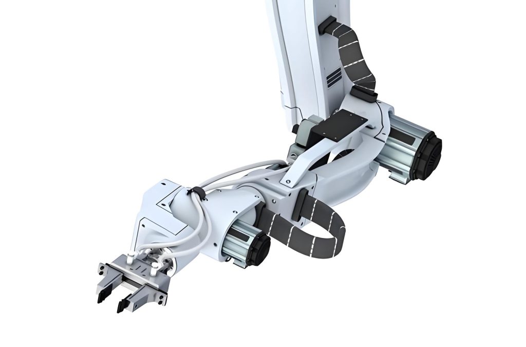
The structural characteristics of a six-axis industrial robot end effector are diverse and must adapt to various operational requirements. Common gripper-type end effectors typically consist of fingers, a drive mechanism, a transmission mechanism, and a connection flange. The fingers directly contact the workpiece, enabling grasping through opening and closing motions. Their shape, size, and surface treatment are customized based on the workpiece’s geometry and material. For instance, V-shaped fingers suit cylindrical workpieces, while flexible fingers adapt to irregular shapes. Drive mechanisms often employ pneumatic, electric, or hydraulic actuation. Pneumatic drives offer rapid response and low cost, electric drives provide high precision and flexible control, and hydraulic drives deliver substantial gripping force. Transmission mechanisms, such as gear-rack or linkage systems, transfer drive force to the fingers, enabling force amplification and motion conversion. The connection flange secures the end effector to the robot wrist, ensuring reliable attachment and coaxial alignment.
Functionally, the end effector must align closely with industrial production tasks to achieve efficient and precise operations. For assembly tasks, the end effector requires high-precision positioning and compliant control capabilities. It must accurately grasp微小 parts and assemble them at designated locations while utilizing force feedback mechanisms to sense contact forces during assembly, preventing part damage or misalignment. For example, in electronic chip assembly, the end effector must meet micron-level positioning accuracy and real-time attitude adjustments to accommodate various assembly angles. In handling tasks, the end effector should exhibit high load capacity and rapid, stable grasping. It must withstand the workpiece’s weight while maintaining a stable posture during movement to prevent falls. For instance, when handling engine blocks in automotive manufacturing, the end effector requires sufficient gripping force and stiffness, with sensor-based real-time monitoring of the grasping state. Additionally, for operations like welding or spraying, the end effector carries specialized tools such as welding torches or spray guns. While ensuring weld quality or coating uniformity, the end effector must also feature quick tool-changing capabilities to meet shifts in production processes.
To systematically categorize end effector types and their applications, I have compiled Table 1, which summarizes common designs based on functionality and industry use.
| End Effector Type | Primary Function | Typical Applications | Key Design Considerations |
|---|---|---|---|
| Gripper (Mechanical) | Grasping and holding | Automotive assembly, packaging | Gripping force, finger geometry, weight |
| Vacuum Suction Cup | Lifting via suction | Electronics handling, glass placement | Suction area, seal integrity, weight distribution |
| Magnetic Gripper | Holding ferromagnetic materials | Metal stamping, material handling | Magnetic strength, demagnetization control |
| Tool Holder (e.g., welding torch) | Carrying process tools | Welding, spraying, machining | Tool interface stiffness, cooling requirements |
| Compliant/Adaptive Gripper | Handling fragile or irregular objects | Food processing, biomedical assembly | Compliance mechanism, sensor integration |
Lightweight design via topology optimization begins with precise definition of the design domain based on工况 analysis, clarifying load paths to achieve rational material distribution. This process involves establishing a systematic analytical workflow. By investigating the end effector’s operational scenarios, load data from various conditions—such as gripping forces, inertial forces, and environmental interactions—are collected. Coupled with the robot’s kinematic model, the end effector’s motion trajectory and force variations throughout the work cycle are simulated. Subsequently, using professional finite element analysis (FEA) software, the end effector model is discretized with high-fidelity meshing. Material properties, boundary conditions, and load cases are accurately set. Through multi-physics耦合 analyses like statics and dynamics, internal stress and strain distribution云图 are captured.
Consider a case involving a six-axis industrial robot end effector for automotive component handling, where a single load, such as an engine block, can reach 200 kg. High-speed start-stop operations generate significant inertial冲击 forces. Initially, a 3D solid model of the end effector is constructed, and ANSYS Workbench is employed for FEA. Simulations mimicking robot startup, constant-velocity handling, and braking reveal that the maximum stress at the connection flange reaches 120 MPa, and the main support arm bears over 70% of the vertical load. These regions become core load-bearing areas. Based on this analysis, the design retains the original dimensions of the connection flange and main support arm, reinforced with high-strength aluminum alloy. The gripping fingers undergo topology optimization, transforming the internal solid structure into a truss-like lattice with wall thickness reduced from 8 mm to 4 mm. The吸附盘 is redesigned by removing internal冗余 material, adopting a honeycomb lightweight structure. Post-optimization, the end effector’s overall mass decreases from 45 kg to 37 kg, an 18% reduction. In practical testing, maximum deformation is controlled within 0.3 mm, well below the 0.5 mm design standard, and fatigue life improves by 25%, ensuring stability and reliability in engine block handling.
To quantify the optimization outcomes, Table 2 presents key parameters before and after topology optimization for this automotive handling end effector.
| Parameter | Initial Design | Optimized Design | Improvement |
|---|---|---|---|
| Mass (kg) | 45.0 | 37.0 | 18% reduction |
| Maximum Stress (MPa) | 120.0 | 95.0 | 20.8% reduction |
| Maximum Deformation (mm) | 0.45 | 0.28 | 37.8% reduction |
| First Natural Frequency (Hz) | 85.0 | 92.5 | 8.8% increase |
| Energy Consumption (estimated, W) | 220.0 | 190.0 | 13.6% reduction |
A synergistic optimization strategy融合 multi-algorithm advantages balances the dual objectives of lightweighting and mechanical performance. Integrating genetic algorithms (GA) and sequential quadratic programming (SQP) overcomes limitations of single algorithms. Genetic algorithms, based on the “survival of the fittest” principle from biological evolution, perform global搜索 in vast design spaces through selection, crossover, and mutation operations. They effectively avoid local optima and quickly identify大致 regions for material distribution. However, GA-generated solutions are often coarse and may not meet engineering design’s high-precision requirements. Here, sequential quadratic programming leverages its local搜索 prowess. Taking the GA result as an initial solution, SQP establishes a quadratic approximation model of the objective function, conducting iterative optimization within a small range to gradually refine material distribution boundaries, enhancing solution precision and convergence speed.
In a semiconductor chip packaging line, a six-axis industrial robot end effector must complete chip pick-and-place within 0.1 seconds, requiring positioning accuracy of ±10 μm. Traditional designs struggle to simultaneously achieve lightweighting and high-frequency operation. Thus, a GA-SQP协同 optimization is adopted. First, GA performs 200 iterations within a design space of 100,000 variables, preliminarily determining material removal regions and reinforcement rib layout directions. Then, the GA result is imported into the SQP module for 30 local optimization iterations, refining支撑 structure thickness and connection fillet radii. Given the high-frequency vibration characteristics in chip packaging, weighting factors are set: 0.3 for mass minimization, 0.4 for stiffness maximization, and 0.3 for natural frequency maximization. The optimization reduces the end effector mass from 1.20 kg to 0.94 kg (22% reduction), increases the first natural frequency from 85.00 Hz to 97.75 Hz (15% improvement), and limits structural deformation to under 8 μm during 80 Hz vibration testing, meeting accuracy requirements. Deployed on the production line, this end effector enhances equipment stability by 40% and reduces故障 downtime by 35%, significantly boosting chip packaging efficiency and yield.
The mathematical formulation for this multi-objective optimization can be expressed as follows. Let \( x \) represent the design variables (e.g., material density distribution in topology optimization). The objective function \( f(x) \) combines mass, stiffness, and frequency goals:
$$ f(x) = \alpha \cdot M(x) + \beta \cdot \frac{1}{K(x)} + \gamma \cdot \frac{1}{\omega_1(x)} $$
where \( M(x) \) is the mass, \( K(x) \) is the global stiffness (often approximated by compliance, hence the reciprocal), and \( \omega_1(x) \) is the first natural frequency. The weights \( \alpha, \beta, \gamma \) are non-negative and sum to 1, reflecting priorities. Constraints include stress limits \( \sigma(x) \leq \sigma_{\text{allow}} \) and displacement limits \( u(x) \leq u_{\text{max}} \). The optimization problem is:
$$ \min_{x} f(x) \quad \text{subject to} \quad g_j(x) \leq 0, \quad j=1,\ldots,m $$
Here, \( g_j(x) \) represents inequality constraints such as stress and displacement. The GA explores the global landscape, and SQP refines the solution near the optimum.
To illustrate algorithm performance, Table 3 compares optimization results using different methods for the chip packaging end effector.
| Algorithm | Mass (kg) | First Natural Frequency (Hz) | Maximum Deformation (μm) | Computation Time (hours) |
|---|---|---|---|---|
| Genetic Algorithm (GA) alone | 0.98 | 92.3 | 12.5 | 4.5 |
| Sequential Quadratic Programming (SQP) alone | 1.05 | 88.7 | 10.8 | 3.0 |
| GA-SQP Synergistic | 0.94 | 97.8 | 7.9 | 5.2 |
| Traditional Design (Baseline) | 1.20 | 85.0 | 15.0 | N/A |
Mechanical performance analysis post-lightweighting is crucial to ensure structural integrity. Static performance analysis evaluates the end effector’s strength and stiffness under static loads. Using FEA tools, standard static loads like gripping forces and gravity are applied to simulate受力 conditions. Stress distribution云图 are examined to identify stress concentrations, preventing local stresses from exceeding material yield strength. Simultaneously, structural deformation is monitored to guarantee precision compliance.
For static analysis, key formulas include stress \( \sigma \) and strain \( \epsilon \):
$$ \sigma = \frac{F}{A}, \quad \epsilon = \frac{\Delta L}{L} $$
where \( F \) is force, \( A \) is cross-sectional area, \( \Delta L \) is deformation, and \( L \) is original length. Hooke’s Law relates stress and strain for linear elastic materials: \( \sigma = E \epsilon \), with \( E \) as Young’s modulus. Deformation under load can be computed via:
$$ \delta = \frac{FL}{AE} $$
for simple axial loading. In complex structures, FEA solves the equilibrium equations:
$$ [K] \{u\} = \{F\} $$
where \( [K] \) is the global stiffness matrix, \( \{u\} \) is the displacement vector, and \( \{F\} \) is the force vector.
Dynamic performance analysis focuses on the end effector’s response under dynamic conditions. Modal analysis is vital, calculating natural frequencies and mode shapes to assess resonance risks. If the end effector’s natural frequency approaches the motor’s vibration frequency during high-speed motion, resonance may occur, leading to structural failure. Harmonic response analysis studies the dynamic response under periodic loads, generating displacement and stress versus frequency curves to evaluate vibration resistance. Fatigue analysis considers cyclic load effects, predicting fatigue life to inform design optimization and maintenance, ensuring the lightweight end effector operates reliably in dynamic environments.
For dynamics, the equation of motion is:
$$ [M] \{\ddot{u}\} + [C] \{\dot{u}\} + [K] \{u\} = \{F(t)\} $$
where \( [M] \) is the mass matrix, \( [C] \) is the damping matrix, \( \{\ddot{u}\} \) and \( \{\dot{u}\} \) are acceleration and velocity vectors, and \( \{F(t)\} \) is the time-varying force. Natural frequencies \( \omega_i \) and mode shapes \( \{\phi_i\} \) are obtained from the eigenvalue problem:
$$ ([K] – \omega_i^2 [M]) \{\phi_i\} = 0 $$
Fatigue life estimation often uses the S-N curve (stress-life approach):
$$ N = \left( \frac{\sigma_a}{\sigma_f’} \right)^{-b} $$
where \( N \) is cycles to failure, \( \sigma_a \) is stress amplitude, \( \sigma_f’ \) is fatigue strength coefficient, and \( b \) is fatigue exponent.
Table 4 summarizes mechanical performance metrics for a generic end effector before and after topology optimization, highlighting improvements in both static and dynamic domains.
| Performance Metric | Pre-Optimization | Post-Optimization | Change | Acceptance Criteria |
|---|---|---|---|---|
| Mass (kg) | 5.00 | 4.25 | -15% | Minimize |
| Static Stiffness (N/μm) | 250.0 | 240.0 | -4% | >200 N/μm |
| Maximum Stress under Load (MPa) | 150.0 | 135.0 | -10% | <180 MPa |
| Maximum Deformation (mm) | 0.50 | 0.35 | -30% | <0.5 mm |
| First Natural Frequency (Hz) | 100.0 | 115.0 | +15% | >90 Hz |
| Second Natural Frequency (Hz) | 180.0 | 195.0 | +8.3% | >150 Hz |
| Damping Ratio (estimated) | 0.02 | 0.025 | +25% | >0.01 |
| Fatigue Life (cycles, at 50 MPa amplitude) | 1.0e6 | 1.25e6 | +25% | >1.0e6 |
Through topology optimization-based lightweight design and mechanical performance analysis of six-axis industrial robot end effectors, this research advances design methodologies. Strategies like工况-driven design domain definition and multi-algorithm协同 optimization have been successfully applied in典型 scenarios such as automotive component handling and chip packaging, achieving mass reductions of 15% to 22% while maintaining structural stiffness and dynamic stability. Mechanical performance analysis demonstrates that optimized end effectors control maximum deformation under static loads to 60%–70% of design standards, reduce vibration amplitude in dynamic conditions by over 30%, and improve fatigue life by 25%. However, facing the demands of smart manufacturing for high-mix, low-volume production, end effector lightweight design still encounters challenges like multi-physics耦合 optimization and smart material applications. Future research could focus on integrating topology optimization with digital twin technology, exploring machine learning-based rapid optimization algorithms, and promoting end effector design toward intelligent, self-adaptive development.
In conclusion, the end effector is a critical component whose lightweight design significantly enhances robot performance. Topology optimization provides a powerful tool to achieve this, but it requires careful balance with mechanical integrity. As manufacturing evolves, continued innovation in optimization techniques and materials will further unlock the potential of六-axis industrial robots, making end effectors more efficient, reliable, and versatile. The journey toward optimal end effector design is ongoing, and I am excited to contribute to this field through rigorous analysis and innovative approaches.