
In the realm of modern industrial automation, rotary vector reducers have emerged as a cornerstone for high-precision motion control, particularly in robotics. As a key component in industrial robots, the rotary vector reducer directly influences operational accuracy, efficiency, and longevity. From my perspective, the drive toward “Industry 4.0” and smart manufacturing has intensified the demand for ultra-precise rotary vector reducers, pushing researchers and engineers to delve deeper into factors affecting their transmission accuracy. In this article, I will explore the intricate dynamics of rotary vector reducers, focusing on error sources, control methodologies, and advanced techniques to enhance performance. By leveraging formulas, tables, and structural insights, I aim to provide a comprehensive analysis that underscores the criticality of precision in these devices.
The rotary vector reducer, often abbreviated as RV reducer, is a type of high-precision reduction gear that combines a planetary gear stage with a cycloidal pinwheel stage. This dual-stage design endows the rotary vector reducer with exceptional characteristics: high torsional stiffness, large reduction ratios, compact size, and minimal backlash. These attributes make the rotary vector reducer ideal for joint drives in industrial robots, where precise positioning and repeatability are paramount. However, achieving and maintaining transmission accuracy in a rotary vector reducer is a multifaceted challenge, influenced by design tolerances, manufacturing processes, assembly techniques, and operational conditions. I will dissect each of these aspects to offer a holistic view on optimizing rotary vector reducer performance.
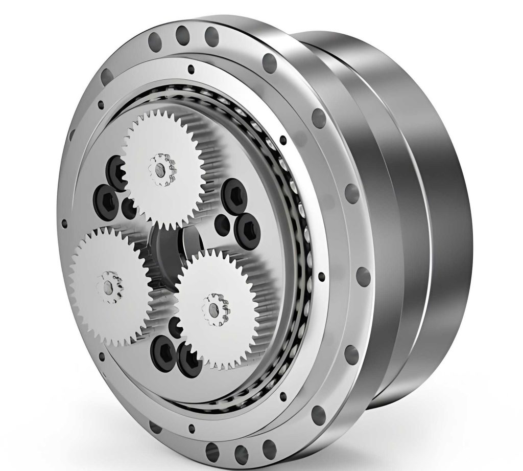
To quantify transmission accuracy in a rotary vector reducer, two primary metrics are used: backlash and transmission error. Backlash, often referred to as回差, is the angular displacement lost when reversing direction, while transmission error denotes the deviation between expected and actual output positions. In high-end applications, such as precision robotics, rotary vector reducers must exhibit backlash below 1.5 arcminutes and transmission error under 1.0 arcminutes. These stringent requirements necessitate a thorough understanding of error propagation within the rotary vector reducer’s architecture. The rotary vector reducer’s structure comprises an input shaft, a first-stage planetary gear system (with sun gear, planet gears, and crankshafts), and a second-stage cycloidal drive (with cycloidal discs, pin gears, and an output shaft). Each component introduces potential inaccuracies, making error analysis a complex but essential endeavor.
From my analysis, errors in a rotary vector reducer can be categorized into design and manufacturing errors, assembly errors, and operational errors. Design and manufacturing errors stem from dimensional inaccuracies in components like gears, pins, and bearings, while assembly errors arise from misalignments and improper fits during integration. Operational errors include wear, thermal expansion, and lubrication issues over time. The rotary vector reducer’s sensitivity to these errors is particularly pronounced in the cycloidal stage, where the interaction between cycloidal discs and pin gears dictates overall precision. To illustrate, I have summarized key error factors in Table 1, highlighting their impact on backlash and transmission error.
| Error Category | Specific Factor | Primary Effect on Accuracy | Typical Tolerance Range |
|---|---|---|---|
| Design & Manufacturing | Cycloidal disc tooth profile deviation | Increases backlash and transmission error | ±0.005 mm |
| Design & Manufacturing | Pin gear diameter variation | Alters meshing clearance, affecting backlash | ±0.002 mm |
| Design & Manufacturing | Bearing radial play | Contributes to overall backlash accumulation | ≤0.01 mm |
| Assembly | Misalignment of crankshafts | Induces uneven load distribution, increasing error | ≤0.02 mm |
| Assembly | Improper preload in bearings | Can reduce backlash but may increase friction | Specified by manufacturer |
| Operational | Wear of cycloidal teeth | Gradually degrades accuracy over time | Monitor via periodic inspection |
| Operational | Thermal deformation | Alters clearances under temperature fluctuations | Material-dependent |
One of the most critical aspects in enhancing rotary vector reducer accuracy is the modification of cycloidal disc tooth profiles, commonly known as修形. This process adjusts the theoretical cycloidal curve to account for elastic deformations, lubrication needs, and assembly tolerances. In my experience, three primary modification methods are employed: equidistant modification,移距 modification, and转角 modification. Each method alters the tooth profile in distinct ways, influencing the number of meshing teeth and contact forces. For instance, equidistant modification shifts the profile radially, while移距 modification translates it, and转角 modification rotates it. The choice of method depends on the specific rotary vector reducer design and desired performance characteristics. To quantify these modifications, I use the following formulas, where Δr represents the modification amount, θ is the rotation angle, and r_p is the pin gear radius.
For equidistant modification, the modified tooth profile radius r_e can be expressed as:
$$ r_e = r_0 + \Delta r $$
where r_0 is the theoretical radius. For移距 modification, the profile is shifted by a distance δ:
$$ x’ = x + \delta \cos(\phi), \quad y’ = y + \delta \sin(\phi) $$
where (x, y) are original coordinates and φ is the phase angle. For转角 modification, a rotation angle α is applied:
$$ x” = x \cos(\alpha) – y \sin(\alpha), \quad y” = x \sin(\alpha) + y \cos(\alpha) $$
These modifications reduce the number of simultaneously meshing teeth, which increases load per tooth but can minimize backlash if optimized correctly. In a rotary vector reducer, the optimal modification amount balances deformation compensation with minimal backlash impact. From my calculations, the total deformation δ_total in the cycloidal meshing includes contact deformation between teeth and deformation at the pin gear housing interface. This can be modeled using Hertzian contact theory:
$$ \delta_{total} = \delta_{mesh} + \delta_{housing} = \frac{F^{2/3}}{K_{mesh}} + \frac{F}{K_{housing}} $$
where F is the meshing force, K_mesh is the contact stiffness coefficient for teeth, and K_housing is the stiffness for the housing interface. By simulating these deformations, I can derive the force distribution and identify the best modification strategy for a given rotary vector reducer. Table 2 compares the three modification methods based on their effects on meshing characteristics.
| Modification Method | Effect on Meshing Teeth Count | Impact on Backlash | Typical Application Scenario |
|---|---|---|---|
| Equidistant Modification | Reduces by 10-20% | Can decrease if optimized | High-load rotary vector reducers |
| 移距 Modification | Reduces by 15-25% | Variable, depends on shift direction | Precision rotary vector reducers with tight tolerances |
| 转角 Modification | Reduces by 5-15% | Generally increases slightly | Rotary vector reducers requiring smooth motion |
Beyond tooth profile modification, controlling tolerances during manufacturing is vital for rotary vector reducer accuracy. In the first-stage planetary gears, errors in center distance or gear tooth thickness have a lesser impact on backlash, allowing for relaxed tolerances. However, for the second-stage cycloidal components, even micron-level deviations can significantly affect performance. From my perspective, key dimensions such as cycloidal disc tooth spacing, pin gear hole positions, and crankshaft eccentricity must be tightly controlled. For example, the eccentricity error e_c of crankshafts should satisfy:
$$ e_c \leq \frac{T}{2\pi} \cdot \frac{1}{N} $$
where T is the allowable backlash in radians, and N is the reduction ratio. This ensures that cumulative errors remain within acceptable limits for the rotary vector reducer. Additionally, material selection and heat treatment play crucial roles; high-quality alloy steels with carburizing or nitriding enhance wear resistance and dimensional stability in rotary vector reducers.
Assembly precision is another cornerstone for optimizing rotary vector reducer performance. Misalignments during assembly can introduce parasitic errors that degrade accuracy. I recommend using specialized fixtures and alignment tools to ensure concentricity between components. Preload adjustment in bearings is particularly critical; too little preload increases backlash, while too much can cause excessive friction and heat generation. The optimal preload force F_preload can be estimated based on bearing specifications and operational loads:
$$ F_{preload} = k \cdot \sqrt[3]{F_{operational}} $$
where k is a constant derived from bearing geometry and material. In rotary vector reducers, automated assembly lines with laser alignment systems have proven effective in minimizing human error. Furthermore, lubrication management is essential; using high-purity oils with anti-wear additives reduces friction and prevents clogging in oil passages, thereby maintaining accuracy over the rotary vector reducer’s lifespan.
Operational factors, such as thermal effects and dynamic loads, also influence rotary vector reducer accuracy. During continuous operation, temperature rises can cause thermal expansion, altering clearances. From my analysis, the thermal expansion ΔL can be calculated as:
$$ \Delta L = \alpha \cdot L \cdot \Delta T $$
where α is the coefficient of thermal expansion, L is the characteristic length, and ΔT is the temperature change. For a rotary vector reducer, this may affect the housing and gear dimensions, necessitating materials with low thermal expansion coefficients or active cooling systems. Dynamic loads from robotic motions induce vibrations that can exacerbate backlash; thus, integrating vibration damping materials or using finite element analysis (FEA) to optimize structural rigidity is advisable. I often employ FEA simulations to predict stress distribution and deformation in rotary vector reducers under various load conditions, enabling proactive design improvements.
To encapsulate the control strategies for enhancing rotary vector reducer accuracy, I have compiled Table 3, which outlines actionable measures across the product lifecycle. These measures, derived from my experience, emphasize a systematic approach to precision engineering.
| Lifecycle Stage | Strategy | Key Actions | Expected Impact on Accuracy |
|---|---|---|---|
| Design | Optimized tooth profile modification | Use computational models to determine best修形 method | Reduces backlash by up to 30% |
| Manufacturing | Tight tolerance control | Implement CNC grinding with sub-micron precision | Minimizes dimensional errors, improving consistency |
| Assembly | Precision alignment and preload | Utilize robotic assembly with real-time monitoring | Ensures uniform load distribution, cuts backlash |
| Operation | Regular maintenance and lubrication | Schedule oil changes and component inspections | Prolongs accuracy retention, reduces wear-induced errors |
| Monitoring | Real-time performance tracking | Install sensors to measure backlash and temperature | Enables predictive maintenance for rotary vector reducers |
In conclusion, the transmission accuracy of rotary vector reducers is a multifaceted issue that demands attention from design through operation. As a critical component in high-precision robotics, the rotary vector reducer’s performance hinges on meticulous error control and advanced engineering techniques. By leveraging modification methods, tight tolerances, precision assembly, and proactive maintenance, manufacturers can achieve the sub-arcminute accuracy required for modern industrial applications. From my viewpoint, ongoing research into materials, lubrication, and digital twins will further push the boundaries of rotary vector reducer capabilities. Ultimately, mastering these factors not only enhances robotic precision but also drives innovation in automation, solidifying the rotary vector reducer’s role as a linchpin in the smart factory era. I encourage engineers to adopt a holistic approach, integrating simulation, testing, and continuous improvement to unlock the full potential of rotary vector reducers in diverse applications.