
The rotary vector reducer, a precision speed reducer renowned for its high reduction ratio, compact structure, and excellent torsional stiffness, serves as a core transmission component in industrial robots. Understanding its dynamic behavior under operational conditions is paramount for ensuring reliability and longevity. This article presents a comprehensive analysis of the vibration characteristics of a rotary vector reducer, integrating advanced simulation methodologies with experimental validation. The primary objective is to elucidate the influence of key operational parameters—specifically input rotational speed and output load torque—on the dynamic response of the reducer.
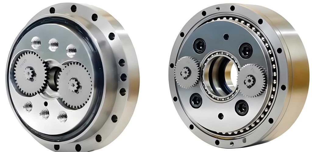
The fundamental operating principle of the rotary vector reducer involves a two-stage reduction mechanism. The first stage is a standard involute gear train, where a pinion drives a planetary gear. The second, and defining, stage is a cycloidal drive. The planetary gear is connected to eccentric shafts, which impart an orbital motion to cycloid disks. These disks mesh with a stationary ring of pinwheels (or pins). This interaction converts the eccentric motion into a slow, high-torque rotation of the planet carrier, which serves as the output. The kinematic relationship dictates a very high reduction ratio, typically ranging from 30 to over 180, making the rotary vector reducer indispensable for precision motion control.
Dynamic Analysis Fundamentals
A thorough investigation into the vibration characteristics of a mechanical system like the rotary vector reducer begins with foundational dynamic analyses: modal analysis and multi-body dynamics.
Modal Analysis
Modal analysis is employed to determine the inherent vibration properties—natural frequencies and mode shapes—of the rotary vector reducer assembly. These properties are independent of external loads and are crucial for identifying potential resonance conditions. The general equation of motion for a multi-degree-of-freedom system is:
$$ \mathbf{M}\ddot{\mathbf{u}} + \mathbf{C}\dot{\mathbf{u}} + \mathbf{K}\mathbf{u} = \mathbf{F} $$
where $\mathbf{M}$ is the mass matrix, $\mathbf{C}$ is the damping matrix, $\mathbf{K}$ is the stiffness matrix, $\mathbf{u}$ is the displacement vector, and $\mathbf{F}$ is the force vector. For undamped free vibration analysis ($\mathbf{F}=0$, $\mathbf{C}=0$), the equation reduces to an eigenvalue problem:
$$ (\mathbf{K} – \omega_i^2 \mathbf{M})\boldsymbol{\phi}_i = 0 $$
Solving this yields the eigenvalues $\omega_i^2$ and eigenvectors $\boldsymbol{\phi}_i$, from which the natural frequencies $f_i = \omega_i / 2\pi$ and corresponding mode shapes are derived. Constrained modal analysis, where boundary conditions simulating the reducer’s mounting are applied, provides the most relevant insight for operational vibration assessment.
Rigid-Flexible Coupled Dynamics
To accurately simulate the dynamic response of the complex rotary vector reducer under operational loads, a rigid-flexible coupled dynamic approach is essential. This method treats components with significant elastic deformation (like cycloid disks, pins, and eccentric shafts) as flexible bodies, while modeling stiffer components (like the planet carrier housing) as rigid bodies. This significantly improves computational efficiency while capturing critical nonlinearities like time-varying meshing stiffness, contact deformations, and friction.
The motion of flexible bodies is described using a combination of boundary node displacements and modal coordinates. The Craig-Bampton method is a widely used technique for component mode synthesis. The physical displacement $\mathbf{u}$ is approximated by:
$$ \mathbf{u} = \boldsymbol{\Phi}_{cb} \begin{Bmatrix} \mathbf{x} \\ \mathbf{q} \end{Bmatrix} = \begin{bmatrix} \mathbf{I} & \mathbf{0} \\ \boldsymbol{\Phi}_R & \boldsymbol{\Phi}_L \end{bmatrix} \begin{Bmatrix} \mathbf{x} \\ \mathbf{q} \end{Bmatrix} $$
where $\boldsymbol{\Phi}_{cb}$ is the Craig-Bampton transformation matrix, $\mathbf{x}$ are physical displacements at boundary nodes, $\mathbf{q}$ are modal coordinates, $\boldsymbol{\Phi}_R$ is the matrix of constraint modes, and $\boldsymbol{\Phi}_L$ is the matrix of fixed-interface normal modes. Substituting into the equations of motion and pre-multiplying by $\boldsymbol{\Phi}_{cb}^T$ yields a reduced system:
$$ \mathbf{M}_{cb} \begin{Bmatrix} \ddot{\mathbf{x}} \\ \ddot{\mathbf{q}} \end{Bmatrix} + \mathbf{K}_{cb} \begin{Bmatrix} \mathbf{x} \\ \mathbf{q} \end{Bmatrix} = \boldsymbol{\Phi}_{cb}^T \mathbf{F} $$
with the reduced mass and stiffness matrices:
$$ \mathbf{M}_{cb} = \begin{bmatrix} \mathbf{M}_{bb} & \mathbf{M}_{bq} \\ \mathbf{M}_{qb} & \mathbf{M}_{qq} \end{bmatrix}, \quad \mathbf{K}_{cb} = \begin{bmatrix} \mathbf{K}_{bb} & \mathbf{0} \\ \mathbf{0} & \mathbf{K}_{qq} \end{bmatrix} $$
This coupled system can be solved efficiently to simulate the transient dynamic response of the entire rotary vector reducer assembly, including vibration signals at specified locations.
Virtual Prototype Modeling and Simulation of the Rotary Vector Reducer
Model Establishment
A detailed 3D assembly model of an RV-20E type rotary vector reducer was created. To balance simulation fidelity with computational cost, minor features like fillets and threads were simplified. A strategic rigid-flexible body assignment was implemented:
- Flexible Bodies: Components subject to significant elastic deformation and nonlinear contact, such as the pinion, planetary gear, cycloid disks, pinwheels, and eccentric shafts, were modeled as flexible bodies. Their finite element meshes were generated with refinement at contact surfaces.
- Rigid Bodies: The planet carrier (output stage), due to its high relative stiffness and minimal contribution to high-frequency vibration, was treated as a rigid body.
Contact pairs were defined for all gear meshes (pinion-planetary, cycloid-pin) with appropriate friction coefficients (0.1 for involute gear pair, 0.08 for cycloid-pin pair). Rotational joints and bushing elements were used to model bearings, with stiffness values derived from analytical calculations. The final meshed assembly contained approximately 147,368 elements and 317,875 nodes. Operational conditions were simulated by applying rotational velocity to the input pinion and a resistive torque to the output planet carrier.
Model Validation via Grey Correlation
Prior to detailed vibration analysis, the kinematic accuracy of the virtual prototype was verified. The simulated output speed under a constant input was compared to the theoretical value based on the design reduction ratio (141:1). The Grey Correlation method was used to quantify the similarity between the theoretical and simulated speed trends. The grey correlation coefficient $\rho_i$ and overall degree of correlation $r$ are given by:
$$ \rho_i = \frac{\min_i |x_i – y_i| + \xi \max_i |x_i – y_i|}{|x_i – y_i| + \xi \max_i |x_i – y_i|} $$
$$ r = \frac{1}{N} \sum_{i=1}^{N} \rho_i $$
where $x_i$ and $y_i$ are data sequences, and $\xi$ is the distinguishing coefficient (taken as 0.5). For input speeds of 200, 400, and 600 rpm under load, the correlation degrees were calculated as 0.800, 0.822, and 0.887, respectively. All values significantly exceed the threshold of 0.5, confirming that the virtual prototype of the rotary vector reducer accurately captures the fundamental kinematic behavior.
Whole-Assembly Constrained Modal Analysis
A constrained modal analysis was performed on the full rotary vector reducer assembly, with boundary conditions representing its bolted mounting on a test platform. The material properties for key components are listed below:
| Component | Material | Young’s Modulus (GPa) | Density (kg/m³) | Poisson’s Ratio |
|---|---|---|---|---|
| Cycloid Disk | 20CrMo | 219 | 7830 | 0.30 |
| Pinwheel | GCr15 | 206 | 7900 | 0.30 |
| Pin Ring | QT450 | 169 | 7050 | 0.26 |
The first six natural frequencies and their corresponding mode shapes are summarized as follows:
| Mode Order | Frequency (Hz) | Primary Mode Shape Description |
|---|---|---|
| 1 | 697.25 | Torsional vibration of eccentric shafts about central axis. |
| 2 | 1,772.6 | Torsional vibration of planet carrier about central axis. |
| 3 | 4,707.2 | Radial vibration of planet carrier and cycloid disks in vertical plane. |
| 4 | 5,006.0 | Radial vibration of planet carrier and cycloid disks in horizontal plane. |
| 5 | 5,924.7 | Bending vibration of eccentric shafts in horizontal plane. |
| 6 | 6,254.4 | Bending vibration of planet carrier in horizontal plane. |
This analysis indicates that the eccentric shafts, planet carrier, and cycloid disks are the primary components susceptible to resonant vibration within the operational frequency range of a typical rotary vector reducer.
Transient Dynamic Simulation for Vibration Response
Leveraging the validated rigid-flexible coupled model, transient dynamic simulations were conducted to extract vibration acceleration signals. Simulations were run for multiple operating conditions:
- Input Speeds: 200, 400, 600 rpm.
- Output Loads: 0, 60, 120 N·m.
A simulation time of 0.2s with a step size of 0.0002s (equivalent to a 5000 Hz sampling rate) was used. Acceleration data from a specific node (Node ID: 102898) on the housing, primarily in the vertical direction, was extracted for analysis. The time-domain signals were post-processed, and Fast Fourier Transform (FFT) was applied to obtain frequency spectra. The results clearly show that the vibration amplitude increases significantly with rising input speed. The spectral content also changes, with distinct peaks emerging at certain frequencies. The influence of load, while present, appears less dramatic on the spectral distribution compared to speed.
Experimental Validation
Test Setup and Methodology
To validate the simulation findings, vibration tests were performed on an RV-20E rotary vector reducer using a dedicated test rig. The setup constituted a power-open-loop system: a servo motor drove the reducer’s input shaft, and the output shaft was connected to a magnetic powder brake via a torque sensor and an angle encoder, allowing precise control of speed and load.
Vibration data was acquired using piezoelectric accelerometers (sensitivity: 20 mV/(m/s²), frequency range: 0-1000 Hz). Sensors were mounted on the reducer’s housing in both vertical and horizontal radial directions at positions corresponding to areas of high dynamic response. Data was sampled at 2000 Hz. Tests covered the same matrix of operating conditions as the simulations: input speeds of 200, 300, 400, 500, 600 rpm and output loads of 0, 30, 60, 90, 120 N·m. Three independent data sets were recorded per condition for statistical reliability.
Experimental Vibration Signal Characteristics
The measured time-domain acceleration signals exhibited typical behavior for a rotary vector reducer: a complex, periodic pattern superimposed with higher-frequency content. The Root Mean Square (RMS) value of the acceleration was calculated as a global indicator of vibration intensity:
$$ a_{RMS} = \sqrt{\frac{1}{N} \sum_{n=1}^{N} a[n]^2 } $$
The frequency spectra of the experimental signals revealed dominant peaks. For instance, under a 400 rpm, 60 N·m condition, prominent peaks were observed near 236.4 Hz, 317.8 Hz, and 427.5 Hz. These characteristic frequencies are attributed to the meshing frequencies of the gear stages and their harmonics, potentially modulated by the transmission path through the eccentric shafts and bearings of the rotary vector reducer.
Results and Discussion
Feature Analysis: RMS Values
A direct comparison between the simulated and experimental RMS values of vertical acceleration across all tested conditions shows good agreement. The table below summarizes a subset of this comparison:
| Load (N·m) | Speed (rpm) | Simulation RMS (m/s²) | Experiment RMS (m/s²) | Relative Error |
|---|---|---|---|---|
| 0 | 200 | 0.035 | 0.031 | 12.9% |
| 400 | 0.096 | 0.104 | 8.7% | |
| 600 | 0.193 | 0.209 | 7.7% | |
| 60 | 200 | 0.086 | 0.079 | 8.8% |
| 400 | 0.129 | 0.140 | 8.9% | |
| 600 | 0.265 | 0.273 | 3.0% | |
| 120 | 200 | 0.087 | 0.092 | 5.6% |
| 400 | 0.186 | 0.174 | 6.8% | |
| 600 | 0.343 | 0.323 | 6.2% |
The maximum relative error is 12.9%, and most errors are below 10%, indicating the rigid-flexible coupled model of the rotary vector reducer effectively captures the overall vibration energy level. The RMS value increases with both speed and load, with speed exhibiting a more pronounced, non-linear influence, especially at higher loads.
Spectral Analysis and Comparison
The frequency spectra from simulation and experiment were compared. After down-sampling the simulation data to match the experimental sampling rate, FFT analysis was performed. The spectral plots show a strong correspondence in the distribution of major peaks. For example, the simulated peaks at 239.9 Hz, 317.3 Hz, and 411.7 Hz under a specific condition align well with the experimental peaks at 236.4 Hz, 317.8 Hz, and 427.5 Hz. Minor discrepancies in exact frequency and amplitude are expected due to modeling simplifications (e.g., exact bearing stiffness, microscopic surface topography) and experimental noise. Nevertheless, the consistency confirms that the dynamic model of the rotary vector reducer accurately reproduces the fundamental spectral characteristics of its vibration.
Influence of Operational Parameters
1. Effect of Load: Analysis of experimental data with constant speed (e.g., 400 rpm) and varying load shows that load primarily affects the amplitude of vibration rather than its spectral composition. A particular frequency component near 320 Hz was examined. Its amplitude increases approximately linearly with increasing load torque. The overall RMS value also shows a near-linear rise with load at a constant speed, as visualized in experimental data trends. This suggests that increased load raises the average meshing force within the rotary vector reducer, leading to proportionally higher vibration energy, but does not significantly excite new vibration modes.
2. Effect of Rotational Speed: In contrast, varying the input speed of the rotary vector reducer has a dramatic and non-linear impact on both the amplitude and frequency content of the vibration. As speed increases, the RMS value rises sharply. Furthermore, the spectral distribution changes significantly: the amplitudes of existing peaks grow, new harmonic and sideband components emerge, and the entire energy distribution shifts. This is because speed directly governs the excitation frequencies (e.g., gear mesh frequency $f_m = \frac{N \times RPM}{60}$, where N is the number of teeth). As these excitation frequencies change, they interact differently with the fixed natural modes of the structure, potentially approaching or crossing resonant frequencies, thereby altering the dynamic response profoundly. The effect of speed on RMS is conclusively more significant than that of load.
Conclusion
This integrated study employing advanced simulation and experimental techniques provides a detailed characterization of the vibration behavior of a rotary vector reducer. A high-fidelity rigid-flexible coupled dynamic model was developed and validated, demonstrating its capability to predict both kinematic output and dynamic vibration response. Constrained modal analysis identified the eccentric shafts, planet carrier, and cycloid disks as critical components governing the system’s natural frequencies. Transient dynamic simulations and experimental tests conclusively revealed the distinct influences of operational parameters: while increased load torque elevates vibration amplitude linearly, changes in input rotational speed have a far more substantial and complex impact, drastically altering both the intensity and spectral signature of the vibration. These insights form a crucial foundation for subsequent research into condition monitoring, fault diagnosis, and dynamic optimization of the rotary vector reducer, ultimately contributing to enhanced performance and reliability in precision robotic applications.