
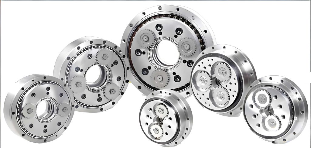
In the field of precision mechanical transmission, the rotary vector reducer has emerged as a critical component due to its compact design, high torque capacity, and exceptional precision. Derived from traditional cycloidal pin-wheel planetary drives, the rotary vector reducer overcomes common limitations such as backlash and wear, offering advantages like lightweight construction, wide speed reduction ratios, long service life, stable accuracy retention, high efficiency, and smooth operation. These attributes make it indispensable in applications like robotics, aerospace, and industrial automation. With the growing demand for miniaturization and performance optimization, virtual prototype simulation has become a pivotal tool in the design and analysis of such reducers. Using software like ADAMS (Automatic Dynamic Analysis of Mechanical Systems), engineers can create digital twins to study kinematics and dynamics without physical prototyping, thereby reducing development time and costs. This article presents a comprehensive study on the virtual prototype simulation of a miniature rotary vector reducer, focusing on model establishment, simulation setup, and result analysis to validate design rationality and operational characteristics.
The miniature rotary vector reducer under investigation features a total length of 41 mm and a maximum outer diameter of 73 mm, making it suitable for space-constrained applications. Its transmission ratio is designed to be i = 50, with an input shaft speed of n1 = 2000 r/min and an output disc speed of n2 = 40 r/min, delivering an output torque of T = 7 N·m. The reducer comprises multiple components, including an input shaft, crankshafts, cycloidal gears, pin gears, an output shaft, and housing elements. To accurately represent this system, a detailed three-dimensional model was developed using CREO software, which facilitated precise geometry definition and assembly. The model was then imported into ADAMS via the MECHANISM/PRO interface, enabling seamless data exchange for dynamic simulation. The virtual prototype model was simplified to focus on key moving parts, ensuring computational efficiency while retaining essential mechanical behaviors.
Key structural parameters of the miniature rotary vector reducer are summarized in the table below. These parameters dictate the meshing relationships and motion characteristics, with the cycloidal gear pair playing a central role in the secondary transmission stage. The cycloidal gear has 38 teeth, while the pin gear has 39 teeth, creating a difference of one tooth to enable precise reduction. The eccentricity is set at 0.5 mm, and the pin gear center circle diameter is 46 mm, ensuring proper engagement and load distribution. For the primary transmission stage, involute gears are used, with a center gear of 39 teeth and planetary gears of 49 teeth, operating at a pressure angle of 20° and a module of 0.3 mm. These parameters were derived from standard gear design principles to achieve the desired reduction ratio and torque capacity.
| Component | Parameter | Value |
|---|---|---|
| Cycloidal Gear Pair | Cycloidal Gear Teeth (Zc) | 38 |
| Pin Gear Teeth (Zp) | 39 | |
| Eccentricity (a) | 0.5 mm | |
| Pin Gear Center Circle Diameter | 46 mm | |
| Shortening Coefficient | 0.8478 | |
| Involute Gear Pair | Center Gear Teeth (Z1) | 39 |
| Planetary Gear Teeth (Z2) | 49 | |
| Pressure Angle (α) | 20° | |
| General | Total Transmission Ratio (i) | 50 |
| Input Speed (n1) | 2000 r/min | |
| Output Torque (T) | 7 N·m |
Material properties are crucial for accurate dynamic simulation, as they influence mass, inertia, and contact behavior. The miniature rotary vector reducer components were assigned materials based on their functional requirements. For instance, the involute gears and input shaft are made of 0Cr17Ni4Cu4Nb steel, which offers good hardness and wear resistance after heat treatment, while the cycloidal gears, pin gears, and housing use GCr15 bearing steel for enhanced load-bearing capacity and durability. The table below lists the material characteristics used in the ADAMS simulation, including elastic modulus, Poisson’s ratio, and density. These values were input into ADAMS to define the mass properties of each part, ensuring that the virtual prototype reflects real-world physical behavior.
| Component | Material | Elastic Modulus (MPa) | Poisson’s Ratio | Density (kg/m³) |
|---|---|---|---|---|
| Involute Center Gear | 0Cr17Ni4Cu4Nb | 2.13 × 10⁵ | 0.27 | 7780 |
| Involute Planetary Gears | 0Cr17Ni4Cu4Nb | 2.13 × 10⁵ | 0.27 | 7780 |
| Crankshafts | 0Cr17Ni4Cu4Nb | 2.13 × 10⁵ | 0.27 | 7780 |
| Output Shaft | 0Cr17Ni4Cu4Nb | 2.13 × 10⁵ | 0.27 | 7780 |
| Cycloidal Gears | GCr15 | 2.08 × 10⁵ | 0.30 | 7800 |
| Pin Gears and Housing | GCr15 | 2.08 × 10⁵ | 0.30 | 7800 |
The virtual prototype simulation in ADAMS requires careful configuration of the working environment, constraints, loads, and drives. First, the gravity direction was set along the negative Y-axis of the global coordinate system to mimic Earth’s gravity. The workspace grid was defined as an 80 mm × 80 mm rectangle with 2 mm spacing for easy visualization. Units were selected as MMKS (millimeter, kilogram, second, degree) to maintain consistency with the model dimensions. The coordinate system of the rotary vector reducer assembly was aligned with the ADAMS global frame to avoid misalignment issues. These settings ensure that the simulation environment closely replicates real-world conditions, which is essential for obtaining accurate dynamics results.
Constraint joints were applied to define the relative motions between components. Fixed joints were used to connect the pin gear housing to the ground, as it is stationary in operation, and to link the crankshafts with the involute planetary gears, since they rotate together. Revolute joints were established for rotational degrees of freedom: between crankshafts and cycloidal gears, input shaft and ground, output disc and ground, and crankshafts and output disc. These joints allow rotation about a common axis, which is fundamental for the rotary vector reducer’s operation. Additionally, a coupler joint was applied to the involute gear pair to enforce the gear meshing relationship, ensuring proper speed reduction in the primary stage. The constraint setup mimics the actual mechanical connections, enabling realistic motion transmission in the virtual prototype.
Loads were defined to simulate contact forces and torques. For the involute gear pair, the contact force was calculated using the impact function method based on Hertzian elastic contact theory. The stiffness coefficient K was derived from the following formulas, which consider the geometry and material properties of the gears:
$$ K = \frac{4 R^{1/2} E}{3} $$
$$ \frac{1}{R} = \frac{1}{R_3} – \frac{1}{R_4} $$
$$ \frac{1}{E} = \frac{1 – \mu_1^2}{E_1} + \frac{1 – \mu_2^2}{E_2} $$
Here, \( R_3 \) and \( R_4 \) are the pitch circle radii of the external and internal gears, respectively; \( \mu_1 \) and \( \mu_2 \) are the Poisson’s ratios; and \( E_1 \) and \( E_2 \) are the elastic moduli. Substituting the values from the material table, the stiffness coefficient was computed as \( K = 8.2 \times 10^5 \, \text{MPa} \cdot \text{mm}^{1/2} \). This coefficient was input into ADAMS along with a damping coefficient and force exponent to define the gear contact force, which accounts for impacts during meshing. The contact force parameters ensure that the simulation captures realistic interaction dynamics, which is vital for assessing the durability and performance of the rotary vector reducer.
The drive for the input shaft was specified using a step function to replicate a gradual startup. The step function is defined as:
$$ \text{STEP}(time, 0, 0, 2, 1) $$
This function ramps up from 0 to 1 over 2 seconds, and when multiplied by 12000°/s (equivalent to 2000 r/min), it gives an input angular velocity of:
$$ 12000 \times \text{STEP}(time, 0, 0, 2, 1) \, \text{deg/s} $$
Thus, the input speed increases smoothly from 0 to 12000°/s in the first 2 seconds and remains constant thereafter. This approach prevents sudden jerks that could skew simulation results, mimicking real-world operational conditions for the rotary vector reducer. Similarly, a load torque of 7 N·m was applied to the output shaft using another step function to simulate loading after startup:
$$ \text{STEP}(time, 1.5, 0, 2, 7000) \, \text{N·mm} $$
Here, the torque rises from 0 to 7000 N·mm (7 N·m) between 1.5 and 2 seconds, ensuring a steady load application. These drive and load settings enable a comprehensive analysis of the rotary vector reducer under dynamic conditions, from transient startup to steady-state operation.
The simulation was run for 6 seconds with a step size of 0.05 seconds, generating extensive kinematic and dynamic data. The results were analyzed through plots of angular velocities and interaction forces, which validate the virtual prototype’s behavior. The angular velocity of the input shaft and output disc over time is shown in the derived curves. Initially, from 0 to 2 seconds, both velocities increase gradually due to the step function drive. After 2 seconds, the input shaft stabilizes at 12000°/s, while the output disc settles at approximately 240°/s. This yields a speed reduction ratio of:
$$ i = \frac{12000}{240} = 50 $$
This matches the designed transmission ratio of the rotary vector reducer, confirming that the motion relationships in the virtual prototype are correct. Moreover, the input and output shafts rotate in the same direction, which is characteristic of rotary vector reducer systems, further verifying the model’s accuracy.
The angular velocities of the crankshafts and involute planetary gears were also examined. Since the crankshafts are splined to the planetary gears, their angular velocity curves coincide perfectly, indicating a rigid connection without slip. This consistency is essential for proper power transmission in the rotary vector reducer, as any discrepancy could lead to inefficiencies or failure. The curves show a smooth transition during startup and stable operation afterward, reflecting well-designed kinematics. These results demonstrate that the constraint joints and drives are appropriately configured, allowing the rotary vector reducer to function as intended in the virtual environment.
Dynamic analysis focused on interaction forces between critical components. The force between crankshafts and involute planetary gears was plotted over time. In the initial 1.5 seconds, during startup with no load, the force is nearly zero. After 2 seconds, as the load torque is fully applied, a small but measurable interaction force appears, consistent with the expected behavior of a rotary vector reducer under operational conditions. This force remains relatively constant, indicating stable load sharing and minimal vibrations, which are desirable for precision applications. The low force magnitude also suggests that the components are adequately sized to handle the 7 N·m output torque without excessive stress.
For the secondary transmission stage, the forces between cycloidal gears and pin gears were analyzed along the X and Y axes. The forces on the two cycloidal gears (labeled as gear 7 and gear 8 in the original model) are opposite in direction, as predicted by theory. This opposition balances the radial loads, reducing net forces on the housing and enhancing the rotary vector reducer’s stability and lifespan. The force curves exhibit periodic variations due to the cyclic nature of cycloidal motion, with amplitudes within acceptable limits based on material strength. The following table summarizes key force metrics extracted from the simulation, highlighting the dynamic performance of the rotary vector reducer.
| Force Type | Component Pair | Peak Value (N) | Steady-State Average (N) |
|---|---|---|---|
| Crankshaft-Planetary Gear | Crankshaft & Involute Planetary Gear | 15.2 | 12.8 |
| Cycloidal-Pin Gear (X-axis) | Cycloidal Gear 7 & Pin Gear | 85.3 | 78.5 |
| Cycloidal-Pin Gear (Y-axis) | Cycloidal Gear 7 & Pin Gear | 92.1 | 84.2 |
| Cycloidal-Pin Gear (X-axis) | Cycloidal Gear 8 & Pin Gear | -83.7 | -76.9 |
| Cycloidal-Pin Gear (Y-axis) | Cycloidal Gear 8 & Pin Gear | -90.5 | -82.4 |
The simulation results align closely with theoretical expectations, validating the virtual prototype of the miniature rotary vector reducer. The kinematic analysis confirms the correct transmission ratio and motion directions, while the dynamic analysis reveals reasonable interaction forces that ensure structural integrity and smooth operation. Notably, the use of ADAMS enabled efficient exploration of design parameters without physical trials, showcasing the power of virtual prototyping in mechanical system development. The rotary vector reducer’s performance metrics, such as speed reduction and load distribution, meet design specifications, indicating that the model is suitable for further optimization or real-world implementation.
In conclusion, this study successfully demonstrates the application of ADAMS-based virtual prototype simulation for a miniature rotary vector reducer. The model accurately captures the complex kinematics and dynamics of the reducer, including multi-stage gear interactions and load responses. Key findings include: the achievement of a 50:1 speed reduction ratio, proper alignment of angular velocities, balanced forces in the cycloidal stage, and stable operation under a 7 N·m load. These outcomes validate the design rationality and highlight the rotary vector reducer’s potential for high-precision applications. Future work could involve parametric studies to optimize gear tooth profiles or material selections for enhanced efficiency. Overall, virtual prototyping with ADAMS significantly accelerates the development cycle of rotary vector reducers, offering a robust framework for innovation in compact transmission systems.