
Throughout my graduate research, I have focused on the challenging problem of enabling a humanoid robot to operate autonomously in complex and unstructured environments. The motivation for this work stems from the fact that real-world applications such as disaster response, home assistance, and even military operations often require robots to traverse uneven terrain, avoid or remove obstacles, and maintain stability under uncertain conditions. While the past four decades have witnessed remarkable advances in bipedal walking and humanoid hardware, the control of a high-degree-of-freedom system in the presence of unknown environmental variations remains an open challenge. In this thesis, I address two representative complex scenarios: walking on unknown uneven ground and pushing an unknown obstacle on flat ground. In both cases, I emphasize stability, energy efficiency, and the effective use of feedback from low-cost sensors. The core contributions include a gait planning framework based on the passive inverted pendulum model, a composite stability controller built around predictive zero moment point tracking, and a practical strategy for removing an unknown obstacle without using hand force sensors. The methods are validated through both high-fidelity simulation and physical robot experiments.
Introduction and Research Context
The concept of an artificial humanlike machine dates back to the late nineteenth century, but it was not until the late 1960s that the first biped walking machines were actually built. Since then, biped humanoid robots have become a central topic in robotics research because they integrate mechanical design, electronics, computer science, sensor technology, and advanced control algorithms. Unlike wheeled or tracked robots, a humanoid robot is expected to operate in environments shaped for humans, such as stairs, narrow corridors, and uneven ground. This expectation gives humanoid robots a unique advantage but also introduces substantial control difficulties. The large number of actuators, the need for dynamic balance, and the uncertainty of real-world environments all contribute to the complexity. For example, a humanoid robot walking on rough terrain must continuously adjust its center of mass, foot placement, and upper body posture. In addition, when a humanoid robot encounters a heavy obstacle, it may need to push the obstacle aside to continue its mission. A successful push requires the robot to estimate the obstacle’s mass and friction, regulate its own posture, and avoid overloading its joints. In this thesis I focus on these two tasks, because together they represent the essence of behavior control in complex environments: the robot either adapts to the environment or actively modifies the environment.
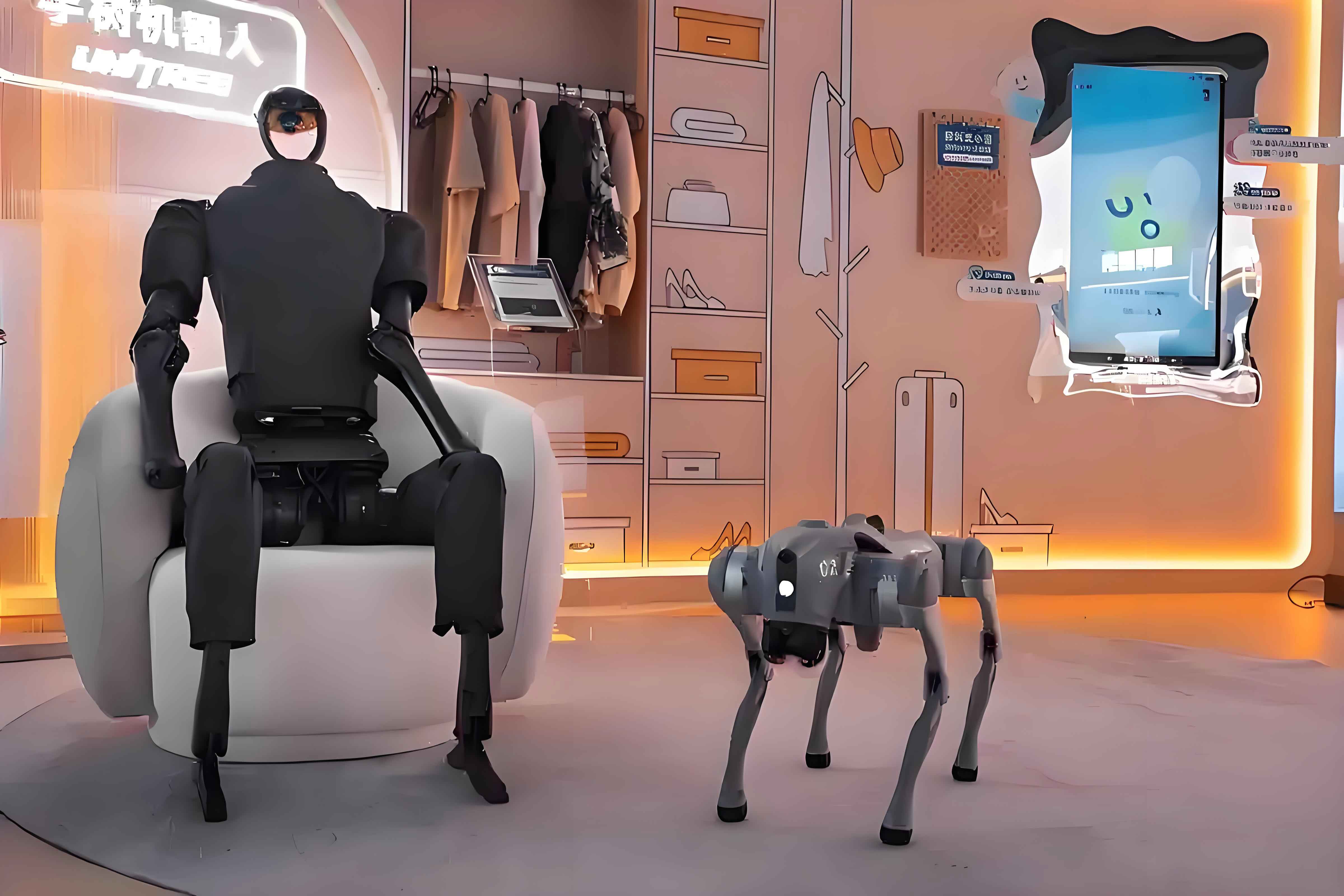
The literature on humanoid robotics is rich and diverse. Many research groups around the world have developed impressive humanoid platforms, including ASIMO, HRP series, Hubo, NAO, LOLA, and Atlas. These robots demonstrate advanced locomotion abilities such as running, climbing stairs, and walking over irregular terrain. In addition to hardware development, gait generation and stability control have been studied extensively. The zero moment point criterion proposed by Vukobratović has become a standard tool for assessing dynamic balance during walking. ZMP is defined as the point on the ground where the resultant moment of gravity and inertial forces acting on all body parts is zero. If the ZMP remains inside the support polygon, the robot is considered stable. Many gait planners therefore generate joint trajectories such that the ZMP follows a desired path inside the support region. Another important approach is the inverted pendulum model, which simplifies the complex multibody dynamics of a humanoid robot into a single point mass connected to the ground by a massless link. The linear inverted pendulum model introduced by Kajita is widely used for real-time gait generation. However, most LIPM-based planners assume a flat ground and do not consider the passive dynamics of the swing leg. In contrast, the passive inverted pendulum model used in this work treats each step as a free fall under gravity, which naturally produces an energy-efficient gait. The PIPM is particularly suited for walking on slopes and for pushing tasks where the robot maintains a forward-leaning posture.
While gait planning provides a reference motion, feedback control is essential for rejecting disturbances. The main stability control methods can be classified into several categories: real-time ZMP tracking control, posture control, compliant landing control, and virtual spring-damper models. In this thesis I combine these methods into a unified controller. First, a predictive controller tracks the desired ZMP trajectory and compensates for the delay caused by the system dynamics. Second, an upper-body posture controller uses attitude feedback to keep the torso upright. Third, a nonlinear touchdown controller modifies the swing leg motion when the foot contacts the ground earlier or later than expected. Fourth, a virtual spring-damper model absorbs the impact through the knee joints. Finally, ground information is decomposed into global and local components, enabling the gait planner to adapt to slopes and unevenness. These techniques have been tested in simulation with the OpenHubo model and in experiments with a small custom-built humanoid robot.
In the context of pushing obstacles, existing studies have used generalized ZMP, hand force sensors, and damping control to stabilize the robot during manipulation. However, many of those methods require expensive force/torque sensors on the wrists. In this thesis I propose a low-cost alternative that relies only on foot force sensors. The robot determines a feasible pushing posture through a trial-and-error process, estimates the obstacle mass and friction using force and acceleration data, and adjusts its body pitch to reduce hip joint loading. Moreover, I compare the energy consumption of walking patterns generated by the PIPM and the LIPM, and show that the passive pattern consumes less power. The important metrics I consider are stability, joint torques, speed, and energy efficiency. These metrics are evaluated in the experimental sections.
Gait Planning Based on the Passive Inverted Pendulum Model
The passive inverted pendulum model treats the humanoid robot as a point mass located at the center of mass, connected to the ground by a massless telescopic leg. The model differs from the more common linear inverted pendulum in that the motion of the pendulum is driven solely by gravity during the single support phase, without any additional joint torque. This assumption leads to an natural and energy-efficient walking pattern. The equations of motion for the pendulum in the sagittal and frontal planes are:
$$
\ddot{\theta} = \frac{g}{l} \sin \theta
$$
$$
\ddot{\varphi} = \frac{g}{l} \sin \varphi
$$
where \(\theta\) is the forward lean angle, \(\varphi\) is the lateral lean angle, \(l\) is the pendulum length, and \(g\) is the gravitational acceleration. For the initial state, I impose the zero-state constraint, meaning that at the beginning of a step the velocity is zero and the potential energy is maximal. Under this condition, the solution for the forward angle as a function of time is:
$$
\theta(t) = \frac{K_q}{2} e^{-K(t – T/2)} – \frac{K_q}{2} e^{K(t – T/2)}, \quad t \in [0, T]
$$
$$
K_q = \frac{S}{2l \sinh(K T / 2)}
$$
$$
K = \sqrt{\frac{g}{l}}
$$
Here \(S\) is the step length and \(T\) is the step duration. This analytical solution provides the desired hip trajectory during the single support phase. The complete gait cycle consists of two single support phases and two double support phases. I set the double support time to 10% of the total cycle to emulate human walking. During the double support phase, the robot smoothly transfers weight from one leg to the other. The foot trajectory is generated using polynomial interpolation with boundary conditions enforcing zero velocity at the moment of landing. After obtaining the hip and foot trajectories, the inverse kinematics of the robot is solved to produce the joint angle profiles for all actuators.
The overall gait planning procedure is summarized in the following table:
| Step | Description | Mathematical Basis |
|---|---|---|
| 1 | Set step length \(S\) and step time \(T\) | Design parameters |
| 2 | Compute the pendulum angle \(\theta(t)\) | Equation (2-4) |
| 3 | Generate foot placement and height profile | Polynomial interpolation |
| 4 | Solve inverse kinematics for joint angles | Robot geometry |
| 5 | Add double support phase transitions | Weight transfer |
For unknown terrain, I use an offline preplanned gait as a baseline and an online planner that adjusts the gait based on real-time measurements. The offline planner assumes flat ground and generates a sequence of steps for the first few seconds. The online planner modifies the step timing and foot placement when the robot detects early or late contact. In addition, I extended the PIPM gait to slopes by introducing a terrain function \(s(t)\) that represents the vertical change of the ground as the robot moves forward. The center of mass height is expressed as:
$$
z_C(x_C) = s(t) + f(x_C)
$$
where \(f(x_C)\) is the height profile of the passive pendulum on flat ground. By substituting this expression into the ZMP formula, I obtain a modified ZMP equation:
$$
x_{ZMP} = x_C – \frac{(s(t) + f(x_C)) \ddot{x}_C + \ddot{s}(t) f'(x_C) + \ddot{s}(t) x_C}{g}
$$
Using the periodicity of the gait, I can solve for \(s(t)\) given the terrain geometry. If the terrain is unknown, the slope is estimated from foot sensor data and the gait is updated in real time. This approach enables the robot to walk on a slope of up to 10 degrees and over small obstacles in the simulation.
Stability Control for Walking on Uneven Ground
Despite the improvements in gait planning, walking on unknown terrain still requires real-time feedback control. I designed a composite controller that combines several modules. The overall control architecture is shown in the block diagram in Chapter 2. The main modules are:
- Predictive ZMP tracking control: This module adjusts the center of mass acceleration to minimize the difference between the actual ZMP and the desired ZMP.
- Upper body posture control: This module uses attitude sensor feedback to keep the torso upright by adjusting the ankle joints.
- Nonlinear touchdown control: This module modifies the swing foot motion when it contacts the ground before the scheduled time, reducing impact.
- Virtual spring-damper model: This module absorbs the residual impact force by varying the leg length through the knee joints.
- Ground information decomposition: This module separates the measured ground inclination into global and local components, enabling the planner to adapt to slopes.
The predictive ZMP controller is derived from the inverted pendulum state space model. Let the state vector be \([x, \dot{x}, \ddot{x}]^T\), the control input be the jerk \(u = \dddot{x}\), and the measured output be the ZMP
$$
p = x – \frac{z_C}{g} \ddot{x}
$$
The discrete-time state space model is:
$$
x_{k+1} = A x_k + b u_k
$$
$$
p_k = c x_k
$$
with:
$$
A = \begin{bmatrix} 1 & \Delta t & \Delta t^2/2 \\ 0 & 1 & \Delta t \\ 0 & 0 & 1 \end{bmatrix}, \quad
b = \begin{bmatrix} \Delta t^3/6 \\ \Delta t^2/2 \\ \Delta t \end{bmatrix}, \quad
c = \begin{bmatrix} 1 \\ 0 \\ -z_C/g \end{bmatrix}^T
$$
where \(\Delta t\) is the sampling time. The performance index for the predictive controller is:
$$
J = \sum_{k=1}^{N} Q \left( p_k^{ref} – p_k \right)^2 + R u_k^2
$$
where \(Q\) and \(R\) are weighting factors. Minimizing \(J\) with respect to the control input sequence yields a controller of the form:
$$
u_k = -K x_k + \sum_{i=1}^{N} f_i p_{k+i}^{ref}
$$
where \(K\) and \(f_i\) are computed from the Riccati equation. In practice I chose \(N=2\), \(Q=2\), and \(R=1\). This predictive control reduces the lag when the desired ZMP changes rapidly, for instance during starting and stopping.
For posture control, I use a PI controller that acts on the ankle joints:
$$
\Delta u_{ankle} = K_p \theta_{err} + K_I \int \theta_{err} dt
$$
$$
\Delta l_L = K_p \theta_{err} + K_I \int \theta_{err} dt
$$
$$
\Delta l_R = -K_p \theta_{err} – K_I \int \theta_{err} dt
$$
Here \(\theta_{err}\) is the measured deviation of the torso from the vertical, and \(\Delta l_L\), \(\Delta l_R\) are the leg length adjustments. The nonlinear touchdown controller sets a maximum falling velocity for the swing foot when the ground is not reached at the expected time. If the foot lands early, the controller decelerates the foot quickly and uses the measured single-support ZMP to estimate the contact point. The virtual spring-damper model is described by the transfer function:
$$
\frac{Z_c(s)}{F_z(s)} = \frac{1}{m s^2 + c s + k}
$$
where \(Z_c\) is the adjusted center of mass height, \(F_z\) is the vertical ground reaction force minus gravity, \(m\) is the robot mass, \(c\) is the damping coefficient, and \(k\) is the stiffness. In the simulation I used \(c = 5000\,\mathrm{N\cdot s/m}\) and \(k = 2000\,\mathrm{N/m}\).
The ground information decomposition computes the overall ground inclination angles:
$$
\alpha_x = \arctan \frac{z_1 – z_2}{x_1 – x_2}
$$
$$
\alpha_y = \arctan \frac{z_1 – z_2}{y_1 – y_2}
$$
where \((x_1,y_1,z_1)\) and \((x_2,y_2,z_2)\) are the positions of the front and rear feet in the robot coordinate system. When the global angle exceeds a threshold, the gait planner regenerates the trajectory as if walking on an inclined surface. This feedback loop greatly improves the robot’s performance on ramps and over small rocks.
Pushing an Unknown Obstacle with Foot Force Feedback
In many practical missions, a humanoid robot must clear a path by pushing aside an obstacle. The pushing operation is complicated by the fact that the obstacle’s mass and the friction coefficient are unknown. Traditional approaches use force/torque sensors in the wrists to measure the interaction force. However, such sensors increase the cost and complexity of the robot. I therefore developed a pushing strategy that uses only the foot force sensors, which are already necessary for walking stability. The proposed method consists of several phases.
First, the robot approaches the obstacle and places its hands on the obstacle surface. Because the robot does not know how much force is needed to move the obstacle, it starts with a very small push distance \(\Delta X\). It then observes the response through the foot sensors. If the feet remain flat on the ground, the push is too small and the robot continues. If the feet begin to tilt backward, this indicates that the pushing force is insufficient and the robot is being pushed backward by the obstacle. In that case the robot adjusts its ankle joints to maintain full contact, then takes a small step backward of distance \(d\). This process repeats until the robot finds a posture where it can push without losing foot contact. If the total backward distance exceeds a threshold \(D\), the robot concludes that the obstacle is immovable and stops. This trial-and-error procedure yields the minimum required pushing force and the initial posture.
Once the robot starts moving, the obstacle acceleration and force can be estimated from the foot sensors. Consider the simplified model shown in Chapter 3, where the robot is a point mass \(m\) and the obstacle is a block of mass \(m_0\) on the ground. The friction force between the obstacle and the ground is \(F_f\). Let \(F_x\) be the horizontal force applied by the robot’s hands. The equation of motion for the obstacle is:
$$
F_x – F_f = m_0 \ddot{x}
$$
The measured center of pressure (COP) at the foot is related to the center of mass position \(x_G\), height \(z_G\), and the hand force. From the moment balance I obtained:
$$
x_{COP} = x_G – \frac{m_0 h \ddot{x} + F_f h + m g z_G \ddot{x}_G}{m g}
$$
where \(h\) is the vertical distance between the hip and the hand contact point. Since \(\ddot{x}\) is not directly measured, I integrated the equation over time to eliminate the acceleration term. The result is:
$$
\int_{0}^{t} x_{COP} m g dt + \int_{0}^{t} F_f h dt = m g \int_{0}^{t} x_G dt – (m_0 + m) z_G \dot{x} + m_0 h \dot{x}
$$
This equation can be solved for \(m_0\). The estimated mass is:
$$
m_0 = \frac{ m g \int_{0}^{t} x_G dt – m z_G \dot{x} – \int_{0}^{t} x_{COP} m g dt – F_f h t }{ z_G \dot{x} – h \dot{x} + \dot{x} z_G / m_0 }
$$
In practice, the estimation is updated during every double support phase. The algorithm alternates between estimating the friction \(F_f\) and the mass \(m_0\) to converge to the true values. In my experiments, the estimated mass was within 20% of the true value after a few steps. The estimation errors were slightly biased due to impact dynamics, but the method was stable enough for practical use.
After estimating the obstacle mass and friction, the robot can compute the required hand force \(F_x\) from Newton’s second law:
$$
F_x = \mu m_0 g + m_0 \ddot{x}
$$
However, since the acceleration is unknown, I used the foot sensor measurements to infer the hand force through the COP equation. The force acting at the hands is then:
$$
F_x = \frac{m g (x_{COP} – x_G) + m z_G \ddot{x}_G}{h}
$$
This value is used to adjust the body pitch angle so that the hip joint torque remains within its limit. The hip joint torque depends on the body posture angle \(\theta_b\) and the hand force:
$$
\tau_2 = F_x h_2 + m g L \sin \theta_b
$$
Here \(L\) is the distance from the hip to the center of mass. To minimize \(\tau_2\) while respecting joint limits, I solved an optimization problem. The optimal posture was computed numerically in real time. This adjustment prevented the hip motors from overloading during the pushing task.
Finally, I studied the energy consumption of the pushing motion. The passive inverted pendulum gait is naturally energy-efficient because the single support phase requires no joint torques beyond gravity. The theoretical energy required for one step in the passive mode is:
$$
E_p = m g l (1 – \cos \theta_{max})
$$
where \(\theta_{max}\) is the maximum lean angle. In contrast, a conventional non-passive gait requires energy to change the kinetic energy of the body:
$$
E_l = \frac{1}{2} m (v^2 – v_0^2)
$$
where \(v\) is the maximum forward speed and \(v_0\) is the minimum speed. When the robot walks at a steady speed, the non-passive gait consumes energy continuously, whereas the passive gait theoretically uses energy only during the double support phase. This difference becomes significant at higher speeds. In the experiments, I measured the power consumption of the robot while pushing an obstacle using both gait patterns. The results are shown in the table below:
| Gait pattern | Minimum power (W) | Maximum power (W) |
|---|---|---|
| Non-passive (LIPM) | 9.6 | 14.1 |
| Passive (PIPM) | 8.2 | 13.0 |
The passive gait reduced both the minimum and maximum power consumption. The difference confirms that the PIPM-based walking pattern is beneficial for energy-limited humanoid robots.
Experiments and Analysis
Simulation of Walking on Uneven Terrain
I conducted simulation experiments using the OpenRAVE platform and the OpenHubo robot model, which is a 1:1 replica of the KAIST Hubo robot with 60 degrees of freedom and six-axis force sensors on the feet. The control cycle was 10 ms. The environment consisted of a flat section of about 1 m, followed by a slope of 10 degrees, on which several small obstacles of height about 10 mm were placed. The robot had to walk over the slope and obstacles. The step length was 15 cm and the step time was 1.4 s. The simulation parameters are summarized in the following table.
| Parameter | Value |
|---|---|
| Pendulum length \(l\) | 82 cm |
| Predictive control weight \(Q\) | 2 |
| Predictive control weight \(R\) | 1 |
| Posture PI proportional gain \(K_P\) | 0.5 |
| Posture PI integral gain \(K_I\) | 0.05 |
| Damping coefficient \(c\) | 5000 N·s/m |
| Stiffness \(k\) | 2000 N/m |
The measured vertical force on the left foot during the walking experiment showed a sharp impulse when the robot first contacted the slope. The virtual spring-damper model absorbed this impulse and the body posture remained stable. The torso pitch angle stayed within ±2 degrees of the upright position after the initial transient. The COP position remained inside the support polygon throughout the trial. The simulation therefore validated the composite control algorithm for walking on unknown rough terrain.
Experiments on Pushing an Unknown Obstacle
The physical experiments used a small humanoid robot with 18 degrees of freedom, a height of 40 cm, and a mass of 4.6 kg. The robot had four one-dimensional force sensors on each foot, allowing the COP and the vertical ground reaction force to be measured. The obstacle was a cardboard box with a mass of 2.2 kg and a friction force on the ground of 6.5 N. The robot was programed to push the obstacle using the proposed trial-and-error method and the passive gait planner. The experimental parameters are listed in the table below.
| Parameter | Value |
|---|---|
| Small push distance \(\Delta X\) | 1.0 cm |
| Backward step distance \(d\) | 2 cm |
| Maximum backward distance \(D\) | 14 cm |
| Pendulum length \(l\) | 25 cm |
| Step length \(S\) | 3.0 cm |
| Step time \(T\) | 1.3 s |
During the pushing task, the robot first determined the starting posture and estimated the minimum force. After the first few steps, it estimated the obstacle mass and friction. The estimation results over five trials are summarized in the following two tables.
| Friction (N) | Trial 1 | Trial 2 | Trial 3 | Trial 4 | Trial 5 |
|---|---|---|---|---|---|
| True value | 6.5 | ||||
| Estimated | 7.0 | 6.6 | 6.8 | 6.9 | 6.8 |
| Mass (kg) | Trial 1 | Trial 2 | Trial 3 | Trial 4 | Trial 5 |
|---|---|---|---|---|---|
| True value | 2.2 | ||||
| Estimated | 2.51 | 2.44 | 2.31 | 2.55 | 2.43 |
All estimates were within 20% of the true values. The slight overestimation was attributed to the impact forces during foot landing. The robot maintained its ZMP inside the support polygon despite the external disturbance from the pushing force. The body posture was adjusted to reduce hip torque. When an additional mass of 0.6 kg was added to the obstacle at \(t=25\) s, the robot detected the change and increased its forward lean after a short adaptation period of about 5 seconds. This behavior demonstrated the robustness of the estimation and adaptation scheme.
The energy consumption of the robot during the pushing task was measured using a power meter. The passive inverted pendulum gait consumed less power than the linear inverted pendulum gait, with minimum and maximum values of 8.2 W and 13.0 W for the passive gait versus 9.6 W and 14.1 W for the non-passive gait. This confirms that the PIPM-based walking pattern is beneficial for prolonging battery life in a humanoid robot.
Discussion of Results
The simulation and experiment results confirm that the proposed control algorithms successfully enable a humanoid robot to perform complex behaviors in challenging environments. The walking algorithm combines gait planning with several feedback loops that compensate for terrain disturbances. The pushing algorithm leverages the foot force sensors as the sole source of contact information, avoiding the need for hand force sensors. The ability to estimate obstacle properties and to adjust posture and gait accordingly makes the robot more autonomous and adaptable. The energy-efficiency comparison highlights the advantages of passive dynamics in humanoid locomotion.
However, the current work has some limitations. The terrain in the simulation was limited to a slope of 10 degrees and small obstacles. The physical pushing experiments were performed only on flat ground. In real-world applications, the robot may encounter steeper slopes, larger obstacles, or irregular shaped objects. The estimation algorithm might fail if the obstacle is not rigid or if it tilts during pushing. The adaptation time after a sudden change in obstacle mass was about 5 seconds, which might be too long for some tasks. Future work should address these issues by incorporating vision and tactile sensing, developing more sophisticated estimation filters, and using the robot’s arms to stabilize itself when the environment changes dramatically.
Conclusion and Future Work
In this thesis I have studied the behavior control of a biped humanoid robot in two specific complex environments: unknown uneven ground and unknown obstacles on flat ground. I first presented a gait planning method based on the passive inverted pendulum model, which generates an energy-efficient walking pattern. I then designed a composite stability controller that combines predictive ZMP tracking, upper body posture control, nonlinear touchdown control, virtual spring-damper absorption, and ground information decomposition. The simulation results showed that the robot could stably walk on a 10-degree slope covered with small obstacles.
For the obstacle pushing task, I proposed a systematic procedure that uses only foot force sensors. The robot first determines a feasible pushing posture through trial and error, then estimates the obstacle mass and friction, and finally adjusts its body posture to avoid joint overload. The experiments on a real humanoid robot demonstrated the effectiveness of the approach. In addition, I showed that the passive inverted pendulum gait consumes less power than the conventional linear inverted pendulum gait during pushing.
There are many avenues for future research. First, the control architecture should be extended to more complex environments with steeper slopes, stairs, or debris. Second, the robot should be equipped with visual perception to detect and classify obstacles before physical interaction. Third, the pushing algorithm could be improved by adding a model predictive controller that simultaneously optimizes the pushing force, body posture, and step timing. Fourth, the use of the robot’s arms and hands for balance during pushing or after unexpected disturbances deserves further investigation. Finally, the integration of learning-based methods could help the robot adapt to unknown environments more quickly. As humanoid robots become more capable, they will be able to operate in increasingly complex environments, assisting humans in a wide range of tasks.