
Humanoid robots have long been a central focus in robotics research, and the most challenging aspect is to enable an embodied robot to walk in a manner that approximates human locomotion using two legs. Most existing humanoid robots are based on serial mechanisms. In this thesis, taking the human body structure as a prototype and starting from a functional bionic perspective, I investigate a novel configuration for an embodied robot. Through the study of the lower limb joints of the human body, I introduce a bridge-type serial mechanism for the hip joint turning motion, and tendon-driven parallel mechanisms for the multi-degree-of-freedom ankle and hip joints. By using equivalent mechanisms to replace joints and combining methods, an overall structure of the embodied robot is constructed, resulting in a hybrid limb configuration where serial and parallel mechanisms coexist.
After analyzing the gait of human walking, I establish a kinematic model for the leg mechanism of the embodied robot, perform forward kinematics calculations, plan the walking pattern, solve the trajectory curve of the center of mass, and obtain the center-of-mass motion trajectory during the walking process. A three-dimensional model of the embodied robot is built in Pro/ENGINEER, motion simulation is carried out, and the center-of-mass trajectory and gait are plotted. The feasibility of the gait planning method is thereby verified. Experiments on the physical prototype are conducted to achieve stable walking and to verify the correctness and effectiveness of the theoretical research. The experimental results demonstrate that the newly designed embodied robot limbs are more human-like, the motion is more flexible, smooth, and continuous, and the robot has a large load-bearing capacity and high motion stability. This work provides a theoretical basis and a new structure for the design of embodied robots.
1. Introduction
The term “robot” originates from the Czech word “robota,” meaning forced labor. Since the first industrial robot was produced in the United States in 1962, robot technology has experienced three stages: simple individual robots, group labor robots, and intelligent robots similar to humans. The future direction is to create robots with perception, thought, and dialogue capabilities. With further scientific and technological development, robot research and design have made significant progress. In the late 1980s, research on human-like walking began, and various biped walking robot prototypes capable of static and dynamic walking have emerged. These studies have addressed fundamental technical issues such as stable balance, mechanism design, gait planning, and control methods. The development of new sensors has made embodied robot technology increasingly mature.
Embodied robot research represents one of the most frontier problems in robotics and serves as an important indicator of a nation’s level of intelligent and automation research. Developed countries have invested heavily in this field. The famous Japanese robotics expert Ichiro Kato pointed out that one of the greatest characteristics a robot should possess is the walking function. Walking is the most basic human movement, but it is also the most automated and complex movement in the biological world. Its perfect realization requires significant changes and innovations in the structural design of robots, thereby strongly promoting the development of related disciplines. The reason embodied robots attract so much attention is that they use two legs to walk and can work and live in the same environment as humans. In contrast, wheeled or tracked robots cannot easily climb stairs, and even a piece of clothing on the floor can hinder their movement. Embodied robots are engineering systems with high order, nonlinearity, nonholonomic constraints, and strong coupling in multiple degrees of freedom, providing an ideal experimental platform for the study of robot kinematics, dynamics, and control theory. In addition, the study of embodied robots has important practical value and scientific significance, as it can promote the development of bionics, artificial intelligence, computer graphics, communications, and other related disciplines. The development of embodied robots also provides strong theoretical and technical support for the development of human prosthetics and opens new fields for service and entertainment robots.
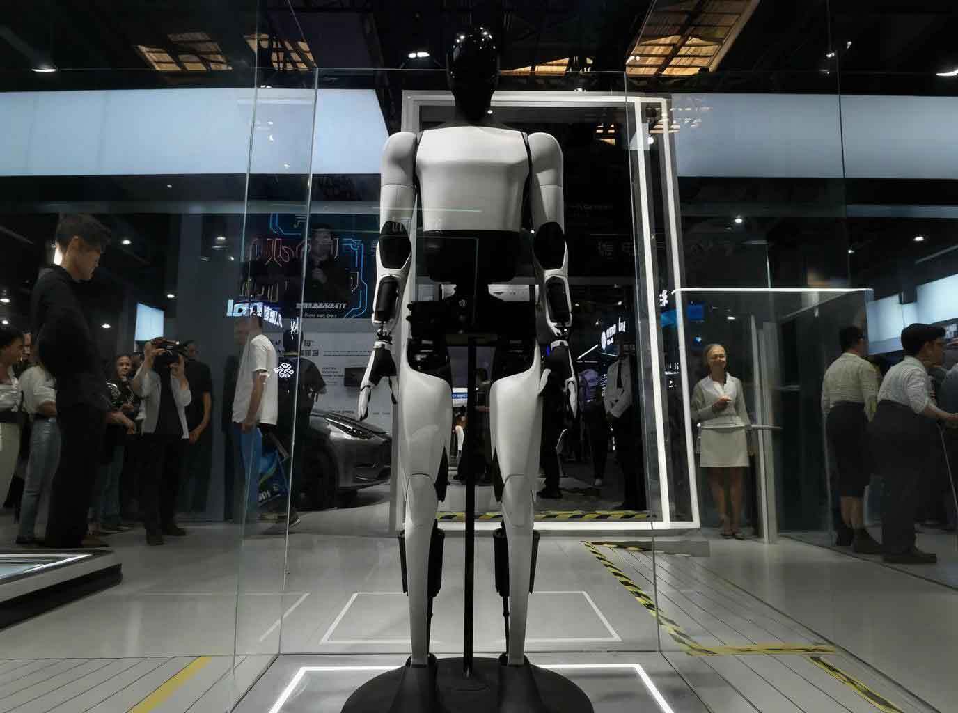
In this thesis, I focus on the lower limb mechanism of an embodied robot. The goal is to design a novel hybrid configuration that combines serial and parallel mechanisms. The proposed structure is inspired by the human musculoskeletal system. The ankle and hip joints are designed as two-degree-of-freedom parallel mechanisms driven by linear actuators, simulating the function of tendons. The hip joint also includes a bridge-type serial mechanism for turning. The knee joint is a single-degree-of-freedom serial joint driven by a tendon-like linkage. This configuration improves the load capacity and motion stability while maintaining a human-like appearance.
2. Human Joint Characteristics and Gait Planning
2.1 Human Body Proportion and Structure
The proportions of the human body are usually measured in head lengths. Most Chinese adults have a height of 7 to 7.5 head lengths. Ancient painting theories mention “standing seven, sitting five, squatting three and a half,” as shown in many anatomy texts. In this research, the structural dimensions of the human body are referenced to design the link lengths of the embodied robot. Table 1 lists typical body measurements for adults. These data provide a basis for determining the proportions of the thigh, shank, torso, and head. The ratio of the lower leg, upper leg, upper body, and head is approximately 2:2.5:3:0.8. The overall size of the embodied robot is designed to match these proportions.
| Measurement | Male (18–60) | Female (18–55) |
|---|---|---|
| Height | 1688 mm | 1586 mm |
| Eye height | 1582 mm | 1484 mm |
| Upper arm length | 338 mm | 308 mm |
| Forearm length | 253 mm | 229 mm |
| Thigh length | 514 mm | 470 mm |
| Calf length | 452 mm | 416 mm |
| Shoulder width | 417 mm | 385 mm |
| Foot width | 96 mm | 88 mm |
| Head height | 245 mm | 232 mm |
2.2 Analysis of Human Joint Features
To make the structure and function of an embodied robot similar to those of a human, it is necessary to analyze the composition, degrees of freedom, and driving forms of human joints. The human body is connected by joints, and joint design is crucial for the embodied robot. The lower limb consists of the hip joint, knee joint, ankle joint, and foot joint. The hip joint is a ball-and-socket joint formed by the pelvis and the femoral head. It has three axes and can perform flexion, extension, abduction, adduction, and rotation. The knee joint is a trochlear joint formed by the femur, tibia, and patella. It is a single-axis joint that mainly performs flexion and extension. The ankle joint is formed by the lower end of the tibia and the fibula, and it is a saddle joint capable of dorsiflexion, plantarflexion, and slight lateral motion. The foot joint is a compound joint composed of the heel and toes and can perform flexion and extension.
Human joint movements are driven by muscles. Each joint is equipped with two groups of opposing muscles: extensors and flexors. This arrangement is similar to a parallel driving mechanism. In the lower limb, the hip and ankle joints are functionally parallel joints, while the knee and toe joints are serial. The motion range of each joint is listed in Table 2.
| Joint | Normal Range of Motion | Structural Type |
|---|---|---|
| Hip | Flexion 120°–140°, Extension 10°–20°, Abduction 30°–50°, Rotation 30°–40° | Parallel |
| Knee | Flexion 120°–150° | Serial |
| Ankle | Dorsiflexion 20°–30°, Plantarflexion 40°–50°, Inversion 20°–30°, Eversion 10°–20° | Parallel |
| Toe | Flexion 30°–50° | Serial |
2.3 Common Gait Planning Methods for Embodied Robots
Gait planning is the process of generating the desired joint trajectories in a walking cycle. Several methods have been developed for embodied robots:
Experimental-based method (CMU): Human walking data are recorded using high-speed cameras and motion capture. The joint angle functions are extracted and then scaled to fit the robot’s dimensions. This method provides a natural and optimized gait reference.
Center of gravity (COG) method: This static method ensures that the projection of the COG remains within the support polygon. It is suitable for slow walking.
Zero Moment Point (ZMP) method: This dynamic method requires the ZMP to stay within the support polygon. It is widely used in modern biped robots.
Two-step planning method: In this thesis, I adopt the two-step gait planning method, which is adapted to the specific characteristics of the embodied robot designed in our laboratory. The first step is to plan the motion of some joints according to the walking requirements. The second step determines the motion of the remaining joints based on the dynamic balance relationship, so that the system can achieve coordinated dynamic motion. The gait flowchart includes three phases: start-up, steady walking, and stop. In the start-up phase, the COG is lowered and shifted to the supporting foot, then a half step is taken. In the steady phase, the feet alternately move forward and the COG is transferred. The stop phase is the reverse of the start-up phase.
3. Structure Design of the Embodied Robot
3.1 Degrees of Freedom Analysis and Configuration
To achieve human-like walking, an embodied robot must have sufficient degrees of freedom (DOF). The proposed robot has 14 DOFs in the lower limbs. Each leg is assigned 7 DOFs: 3 DOFs at the hip (pitch, roll, and yaw), 1 DOF at the knee (pitch), 2 DOFs at the ankle (pitch and roll), and 1 DOF at the toe (pitch). The hip yaw DOF is realized by a bridge-type worm gear mechanism. The hip and ankle pitch/roll DOFs are realized by two-degree-of-freedom parallel mechanisms driven by linear actuators, which are called tendon-driven joints. The knee and toe joints are single-DOF serial joints. Table 3 lists the DOF allocation for each leg.
| Joint | DOF | Motion | Actuation Type |
|---|---|---|---|
| Hip | 3 | Pitch, Roll, Yaw | Tendon parallel (pitch/roll) + Worm gear (yaw) |
| Knee | 1 | Pitch | Tendon single link |
| Ankle | 2 | Pitch, Roll | Tendon parallel |
| Toe | 1 | Pitch | Gear |
3.2 Hybrid Mechanism Design
The lower limb of the embodied robot is designed as a hybrid configuration consisting of parallel mechanism joints and single-DOF serial joints. Figure 3 shows the conceptual layout of the hybrid leg: a two-DOF parallel ball joint at the hip, a single-DOF pitch joint at the knee, a two-DOF parallel ball joint at the ankle, and a single-DOF toe joint. This configuration has several advantages. The actuators can be mounted on the body (thigh and shank), reducing the moving mass of the distal segments. The stiffness and load capacity of the limb are increased, and the axial dimensions are small. The motion is smoother and more continuous compared to conventional serial robots.
The ankle joint is a two-degree-of-freedom tendon-driven mechanism, as shown in the structural diagram. It consists of a fixed platform (shank), a moving platform (foot), and three branches. Two branches are identical active drive branches composed of ball-screw mechanisms with spherical joints. The third branch is a passive constraint branch using a universal (Hooke) joint. The linear actuators (screw-nut units) push or pull the connecting rods through ball joints, causing the foot to rotate about the two axes of the universal joint. This mechanism mimics the human ankle tendons. When the foot is in the air, the shank serves as the fixed platform and the foot as the moving platform. When the foot is on the ground, the roles are reversed. The symmetrical active branches provide coordinated pitch and roll motions.
The hip joint has three DOFs. The two-DOF parallel mechanism for pitch and roll is identical in type to the ankle joint. The yaw DOF is realized by a bridge-type connection structure. Two symmetric worm gears are driven by DC motors. The worm gear provides a high reduction ratio, high load capacity, and self-locking property. This prevents damage when power is suddenly lost or the motor is stalled. The bridge structure allows the robot to turn and also helps shift the center of gravity during lateral movements.
The knee joint is designed as a single-degree-of-freedom tendon-driven joint. A DC motor drives a short screw, moving a nut block that is connected to a short guide rod. The guide rod is connected to the shank plate through a link. As the guide rod moves, the link rotates the knee joint around its axis. This structure is simple and effective, similar to the single-tendon drive of the human knee.
3.3 Selection of Driving Components
The motors and gear reducers are selected based on kinematic and dynamic analyses. After a process of theoretical estimation and simulation verification, the final selections are made. The motors are DC motors with a coreless rotor, manufactured by Maxon. These motors have high performance and low inertia. For example, the hip joint motor is selected as follows: the required joint torque is calculated from the mass distribution and acceleration. The total efficiency is assumed to be 0.7. The load torque on the motor shaft is computed, and the motor with a stall torque sufficiently larger than the driving torque is chosen. The gear reducers are planetary gearheads with high reduction ratios. Table 4 lists the main parameters of the selected motors, and Table 5 lists the gear reducer parameters.
| Model | Rated Power (W) | Rated Voltage (V) | Torque Constant (mNm/A) | Speed Constant (rpm/V) | Stall Torque (mNm) | Max Speed (rpm) | Max Output Power (W) | Efficiency |
|---|---|---|---|---|---|---|---|---|
| Maxon RE-max 29 | 22 | 24 | 24.6 | 388 | 182 | 12000 | 22 | 0.86 |
| Maxon RE-30 | 60 | 24 | 26.8 | 357 | 429 | 12000 | 60 | 0.85 |
| Model | Reduction Ratio | Number of Stages | Max Continuous Torque (Nm) | Max Efficiency | Length (mm) |
|---|---|---|---|---|---|
| GP 26 A | 4.4:1 | 1 | 0.9 | 90% | 22 |
| GP 32 A | 33:1 | 3 | 6.0 | 80% | 34 |
| GP 42 A | 66:1 | 3 | 15.0 | 78% | 50 |
Digital encoders are used for position and speed feedback. The encoder outputs square wave signals that are processed by the control system. Table 6 shows the encoder specifications.
| Model | Counts per Turn | Number of Channels | Max Frequency (kHz) |
|---|---|---|---|
| HEDL 5540 | 500 | 3 | 100 |
| HEDR 5540 | 1000 | 3 | 200 |
3.4 Sensor Configuration
To achieve stable walking, the embodied robot needs sensors to perceive its environment. In this design, four force sensors are mounted under each foot to measure the ground reaction forces and compute the ZMP. The sensors are strain-gauge type pressure sensors with a measurement range of up to 150 N each. They are arranged in a cantilever beam configuration at the four corners of the foot. The measured data are used to calculate the actual ZMP, which is then compared with the desired ZMP for online balance adjustment.
3.5 Overall Design of the Embodied Robot
Based on the DOF configuration and component selection, the detailed mechanical design of the embodied robot is completed. The robot is named “HIT II” in the laboratory context. The total height is 700 mm, the mass is 8.5 kg, and it has 14 DOFs. The lower limbs are assembled from the foot, shank, thigh, and waist subassemblies. A three-dimensional model is built in Pro/ENGINEER, and a physical prototype is manufactured. The robot is capable of stable walking on flat ground, climbing stairs, and turning.
4. Kinematics Analysis of the Embodied Robot
4.1 Leg Kinematic Model
The embodied robot is modeled as a seven-link mechanism, as shown in many biped robot studies. The model consists of two feet, two shanks, two thighs, and a torso. The coordinate system is fixed to the supporting foot. The joint angles are represented by $\theta_i$. For a five-link or seven-link model, the position of each mass center can be expressed as a function of the joint angles. This thesis focuses on the forward kinematics to obtain the workspace and the position of the center of mass.
Let the link lengths be $l_1, l_2, l_3$ for the foot, shank, and thigh, respectively. The coordinates of the ankle, knee, and hip can be expressed as:
$$
x_A = l_1 \cos\theta_1, \quad y_A = l_1 \sin\theta_1
$$
$$
x_K = x_A + l_2 \cos(\theta_1+\theta_2), \quad y_K = y_A + l_2 \sin(\theta_1+\theta_2)
$$
$$
x_H = x_K + l_3 \cos(\theta_1+\theta_2+\theta_3), \quad y_H = y_K + l_3 \sin(\theta_1+\theta_2+\theta_3)
$$
For the entire leg, the forward kinematics can be summarized by a homogeneous transformation matrix:
$$
T = \begin{bmatrix} \cos(\theta_1+\theta_2+\theta_3) & -\sin(\theta_1+\theta_2+\theta_3) & 0 & x_H \\ \sin(\theta_1+\theta_2+\theta_3) & \cos(\theta_1+\theta_2+\theta_3) & 0 & y_H \\ 0 & 0 & 1 & 0 \\ 0 & 0 & 0 & 1 \end{bmatrix}
$$
4.2 Center of Mass Trajectory
For a biped robot in single support phase, the overall center of mass (COM) can be calculated as a weighted average of the mass centers of each link. In the seven-link model, the COM position is given by:
$$
X_G = \frac{\sum_{i=1}^{7} m_i x_i}{\sum_{i=1}^{7} m_i}, \quad Y_G = \frac{\sum_{i=1}^{7} m_i y_i}{\sum_{i=1}^{7} m_i}
$$
where $m_i$ and $(x_i, y_i)$ are the mass and coordinates of the $i$-th link. During walking, the COM trajectory should be planned to maintain stability. The desired COM trajectory in the sagittal plane can be described by a sinusoidal function:
$$
Y_G(t) = \bar{Y} + A_y \sin\left(\frac{2\pi t}{T}\right)
$$
$$
Z_G(t) = \bar{Z} + A_z \cos\left(\frac{2\pi t}{T}\right)
$$
where $\bar{Y}$ and $\bar{Z}$ are the average heights, $A_y$ and $A_z$ are the amplitudes, and $T$ is the step period. In the lateral direction, the COM is shifted to the supporting foot with a smooth transition:
$$
X_G(t) = \frac{B}{2} \sin\left(\frac{2\pi t}{T}\right)
$$
where $B$ is the distance between the two feet.
To solve the lateral joint angles, it is assumed that the front joints are fixed. The robot body remains vertical, so the ankle and hip roll angles are equal and opposite. The COM lateral displacement is related to the roll angle $\phi$ by:
$$
X_G = L \sin\phi
$$
where $L$ is the distance from the ankle to the COM. In the start-up phase, the COM is lowered and shifted to one side. The trajectory can be expressed piecewise.
4.3 Tendon Joint Kinematics
The tendon-driven parallel mechanism at the ankle and hip is modeled as a spatial parallel mechanism. The fixed platform and moving platform are connected by a universal joint at the center and two active branches with spherical joints at both ends. The coordinate frames are defined as shown in the structural diagram. The positions of the spherical joints on the moving platform are represented in the moving frame as $P_i’ = [x_i’, y_i’, z_i’]^T$. The positions of the spherical joints on the fixed platform are $B_i = [x_i, y_i, z_i]^T$. The orientation of the moving frame with respect to the fixed frame is given by the rotation matrix:
$$
R = R_y(\beta) R_x(\alpha)
= \begin{bmatrix} \cos\beta & \sin\beta \sin\alpha & \sin\beta \cos\alpha \\ 0 & \cos\alpha & -\sin\alpha \\ -\sin\beta & \cos\beta \sin\alpha & \cos\beta \cos\alpha \end{bmatrix}
$$
where $\alpha$ and $\beta$ are the two rotation angles about the $x$ and $y$ axes respectively. The vectors from the fixed joints to the moving joints in the fixed frame are:
$$
\mathbf{q}_i = R \mathbf{p}_i’ + \mathbf{t} – \mathbf{b}_i
$$
where $\mathbf{t}$ is the translation vector between the origins of the two platforms. Since the universal joint constrains the origin, $\mathbf{t} = [0,0,z]^T$ for a fixed height. The length of each active branch is constant, and the actuator position is related to the angle through the inverse kinematics.
For a given orientation $(\alpha, \beta)$, the required actuator stroke can be obtained from the distance constraint:
$$
L_i^2 = \|\mathbf{q}_i\|^2
$$
Since the active branches are driven by ball screws, the linear displacement of the nut is $d_i = L_i – L_{i0}$, where $L_{i0}$ is the initial length. The position inverse solution can then be written as:
$$
d_1 = \sqrt{a_1^2 + b_1^2} – L_{10}, \quad d_2 = \sqrt{a_2^2 + b_2^2} – L_{20}
$$
where $a_i$ and $b_i$ are functions of $\alpha$ and $\beta$. The detailed derivation leads to:
$$
d_1 = \sqrt{(A_1 \cos\beta + B_1 \sin\beta \sin\alpha + C_1 \sin\beta \cos\alpha)^2 + \cdots} – L_{10}
$$
This equation establishes the mapping between the actuator displacement and the joint rotation angles. By differentiating with respect to time, the actuator velocity can be obtained, which is used for motion control.
5. Modeling, Simulation, and Experimental Analysis
5.1 Three-Dimensional Modeling
The three-dimensional model of the embodied robot is constructed using Pro/ENGINEER (Pro/E) software. Pro/E is a powerful parametric CAD system with an integrated motion analysis module that allows the user to perform assembly, interference checking, and kinematic simulation. The modeling process begins with creating each part according to the design dimensions. Then, all parts are assembled using appropriate constraints. For moving parts, connections such as pin joints, slider joints, and ball joints are defined. In this embodiment, the screw-nut connection is modeled with a slider joint, the guide rod with a cylindrical joint, and the spherical joints with ball connections. The worm gear and gear pairs are modeled with gear joint constraints.
After the complete assembly, the motion simulation is carried out in the “Mechanism” environment of Pro/E. Servo motors are added to each active joint. The motor speeds are set according to the planned gait. The simulation duration and time step are defined. The motion is then solved and animated. A key frame sequence of the walking gait is obtained, showing the robot stepping forward while maintaining balance. The positions of the center of mass are measured during the simulation.
5.2 Simulation Results
Figures below show the COM trajectories in the X (lateral), Y (vertical), and Z (forward) directions during one gait cycle. The simulation results indicate that the COM trajectory in the lateral direction follows a smooth sine-like curve, shifting from one foot to the other. The vertical COM trajectory has a small fluctuation within ±10 mm, which is acceptable for stable walking. The forward COM trajectory increases monotonically, corresponding to the forward progression of the robot.
| Component | Mass (kg) |
|---|---|
| Foot (each) | 0.45 |
| Shank (each) | 1.10 |
| Thigh (each) | 1.35 |
| Waist | 1.20 |
| Upper body | 1.50 |
| Total | 8.50 |
The simulation also reveals an interference between the ankle universal joint and the toe motor bracket. This issue is resolved by modifying the motor bracket parameters and by utilizing the toe joint to compensate for the limited ankle range. The final simulation demonstrates that the embodied robot can walk following the planned gait without any collision between parts.
5.3 Physical Prototype Experiment
Based on the successful virtual simulation, a physical prototype of the embodied robot is fabricated and assembled. The control system converts the planned joint trajectories into PWM signals, which are sent to the DC motor drivers. The foot pressure sensors provide real-time ZMP information. The robot is initially tested in a slow walking mode on a flat floor. The experimental results show that the robot can walk stably with a step length of 200 mm and a walking speed of 0.1 m/s. The robot is also able to climb stairs and turn. The observed motion is smooth and human-like, validating the effectiveness of the hybrid mechanism and the gait planning method.
The experiments confirm that the tendon-driven parallel joints significantly reduce the torque required at each joint compared to conventional serial joints. The load capacity is increased, and the stability is enhanced. The bridge-type hip joint allows smooth turning. The proposed novel configuration of the embodied robot has thus been proven feasible and effective.
6. Conclusion
In this thesis, I have designed a new type of lower limb mechanism for an embodied robot. The main contributions and conclusions are as follows:
- Based on the analysis of human physiological structure and motion characteristics, I proposed a “tendon-driven” parallel joint mechanism for the ankle and hip joints, and a “bridge-type” mechanism for the hip yaw motion. The embodied robot lower limb has 14 DOFs with a hybrid configuration of serial and parallel mechanisms.
- The three-dimensional model of the embodied robot was built and assembled in Pro/ENGINEER. Kinematic simulation was performed, and the COM trajectories were obtained. The simulation results showed that the designed robot can walk stably according to the planned gait.
- The physical prototype “HIT II” was manufactured and tested. The experimental results demonstrated stable walking and confirmed the effectiveness of the hybrid lower limb design.
- The work provides a theoretical basis and a new structural option for the design of embodied robots. Future work will focus on optimizing the structure to reduce weight and improve dynamic performance, as well as implementing online gait adjustment based on the “offline planning – online tuning” strategy.
The research presented in this thesis contributes to the field of embodied robot design and gait planning. The developed hybrid mechanism offers a promising alternative to conventional serial robots, with improved load capacity, motion flexibility, and human-likeness. Further studies will be carried out to enhance the control algorithms and to explore more complex locomotion tasks.